Key Step for Perception Accuracy in Autonomous Driving: Calibration
The perception accuracy of autonomous driving systems has long been bottlenecked by a commonly overlooked step: up to 90% of issues encountered during vehicle testing—including misalignment among multi-sensor data, ranging errors for obstacles, and lateral offsets in lane-line detection—can be traced back to insufficient calibration accuracy. As the foundational prerequisite for multi-sensor fusion perception, calibration essentially establishes a unified “spatial language” across heterogeneous onboard sensors—such as cameras, LiDARs, and millimeter-wave radars—ensuring their coordinate measurements align precisely in space and integrate into a coherent environmental perception output, rather than generating mutually contradictory individual measurements.
Core Logic and Parameter Classification of Calibration
Calibration fundamentally follows a “reference-standard comparison” process: known-accuracy spatial coordinates are provided as input to the sensor under calibration; simultaneously, the sensor’s measured output is captured. By matching and fitting these two datasets, the functional mapping relationship between them is derived, enabling calculation of the sensor’s actual performance parameters. Industry practice classifies calibration parameters into two broad categories:
1. *Intrinsic parameters*—the sensor’s “innate attributes,” such as camera focal length, lens distortion coefficients, or internal coordinate offsets of LiDAR emitter units—determined solely by the sensor’s inherent optical and mechanical design;
2. *Extrinsic parameters*—the sensor’s “post-installation attributes,” i.e., its six-degree-of-freedom transformation (three rotational angles and three translational distances) relative to the vehicle’s coordinate system—defining how raw sensor measurements map onto true-world spatial coordinates.
Most sensors require at least one calibration at each of three stages: factory production, vehicle integration, and post-deployment maintenance—to guarantee measurement accuracy meets specification requirements.
Coordinate System Transformation in Vehicle-Mounted Camera Calibration
Taking the vehicle-mounted camera as an example, the entire calibration process establishes transformation relationships across four hierarchical coordinate systems:
- The lowest layer is the *pixel coordinate system*, with origin at the top-left corner of the image plane and units in pixels—marking each pixel’s position on the image. However, pixel coordinates cannot directly represent real-world physical dimensions.
- To bridge this gap, coordinates are transformed into the *image coordinate system*, whose origin lies at the image center—enabling computation of the physical size corresponding to each pixel.
- Next comes the *camera coordinate system*, defined with the optical center (lens center of projection) as origin and the optical axis as the Z-axis—modeling the geometric relationship between the image plane and the camera’s spatial pose. The distance from the image coordinate origin to the camera coordinate origin equals the camera’s focal length.
- At the top level lies the *world coordinate system*—the absolute spatial reference frame aligned with the real road environment and vehicle chassis. All sensor parameters must ultimately be registered to this common frame to enable robust multi-sensor data fusion.
A common misconception is that calibration remains valid indefinitely after a single session. In reality, the real-world physical dimension represented by one pixel can vary by over an order of magnitude across different distance ranges: e.g., 0.1 mm per pixel at near range versus ~20 mm per pixel at far range. Relying on single-distance calibration leads to meter-level ranging errors at long range—far exceeding safety requirements for L3+ autonomous driving.
Types and Correction of Vehicle-Mounted Camera Distortion
Vehicle-mounted cameras universally employ lens-based imaging, whose inherent optical properties inevitably induce image distortion. Two primary types dominate current practice:
- *Radial distortion*, commonly experienced as barrel or pincushion distortion. Wide-angle lenses—due to large refraction angles at image edges—typically produce inward-curving barrel distortion, while telephoto lenses tend toward outward-curving pincushion distortion—reminiscent of images taken with a funhouse mirror.
- *Tangential distortion*, typically caused by non-parallel alignment between lens and image sensor plane—producing perspective distortions analogous to photos taken with a tilted smartphone.
If uncorrected via calibration, both distortion types introduce positional errors of several tens of centimeters in obstacle localization and lane-curve estimation—posing immediate safety risks at highway speeds. Once intrinsic parameters and distortion coefficients are obtained, real-time image rectification becomes feasible; combined with extrinsic transformation matrices, this enables accurate monocular camera perception output. For stereo or multi-sensor fusion scenarios, alignment of all sensor parameters to the shared world coordinate system suffices for seamless data fusion.
Classification of Extrinsic Calibration Methods
Industry-standard extrinsic calibration methods fall into two categories:
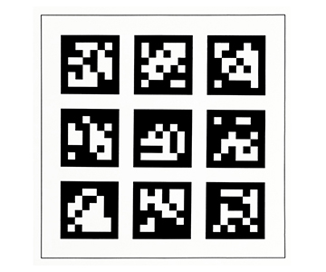
- *Targetless calibration*: leverages naturally occurring static features—e.g., trees, traffic signs, or lane markings—as reference points without requiring specialized equipment. Its main advantage is operational convenience, making it suitable for online dynamic recalibration post-vehicle deployment. However, natural features lack guaranteed positional and dimensional accuracy—limiting achievable calibration precision to the centimeter level, insufficient for R&D or production-line requirements.
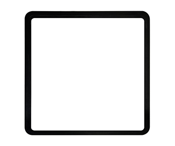
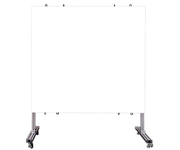
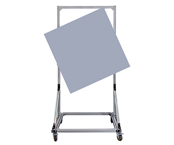
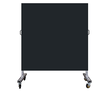
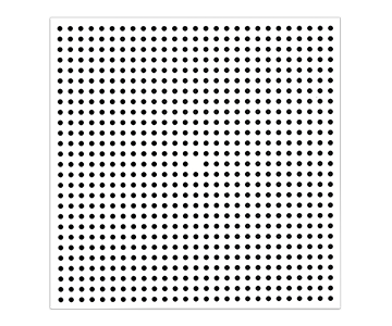
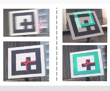
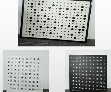
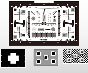
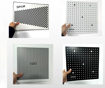
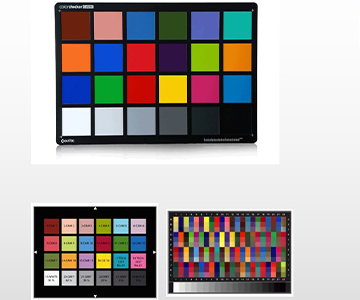
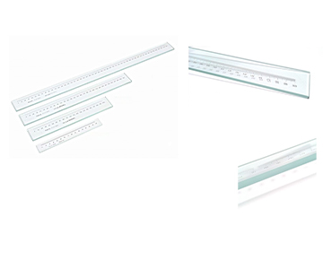
- *Target-based calibration*: employs high-precision standard calibration targets—e.g., boards with known geometric dimensions—as reference artifacts, effectively using a nationally traceable “standard ruler” to calibrate sensor parameters. Accurate transformation parameters are computed via feature-point matching on the calibration target, achieving sub-millimeter calibration precision—the only currently reliable solution for R&D and production-line applications.
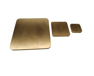
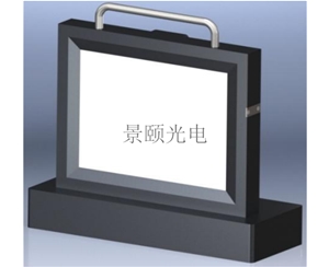
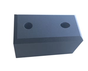
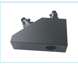
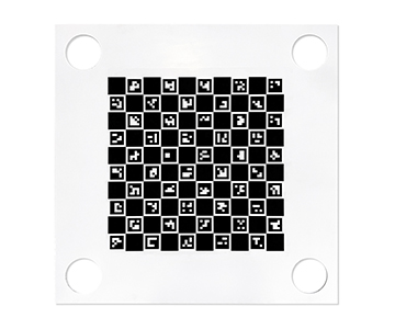
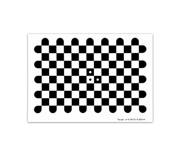
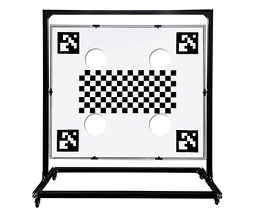
Features and Applications of Jingyi Optoelectronics’ Calibration Boards
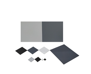
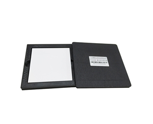
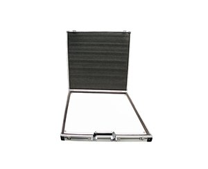
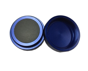
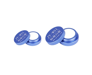
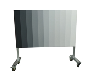
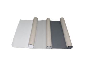
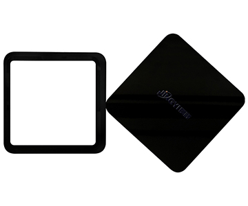
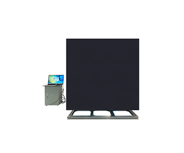
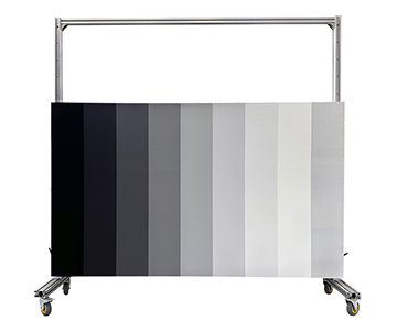
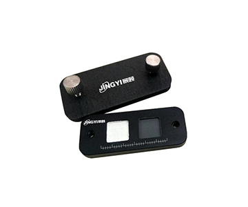
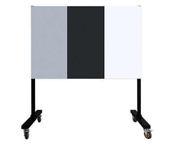
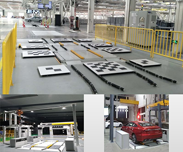
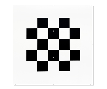
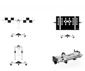
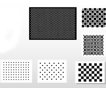
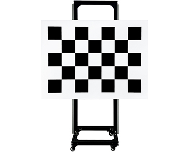
To meet stringent accuracy demands for automotive sensor calibration, Jingyi Optoelectronics has developed the GPG-series chessboard-pattern standard calibration boards—engineered specifically for intelligent driving production lines and environmental stress tests (e.g., extreme temperature cycles). Among them, the GPG1200-7×5-150 model achieves microscale manufacturing precision: coordinate error across all corner points remains below 0.02 mm—fully compliant with automotive-grade requirements for both intrinsic and extrinsic calibration of cameras and LiDARs. Compared to conventional calibration boards, Jingyi’s solution utilizes proprietary substrate materials and surface coatings—achieving >95% reflectance uniformity to prevent overexposure and consequent corner-point detection failure under backlight conditions—and maintaining board dimensional stability with minimal thermal deformation (<0.001%) across the full automotive temperature range (−40°C to +85°C). Whether deployed for winter cold-weather testing in northern regions or summer high-temperature aging validation, it ensures consistent and reliable calibration data.
Test Feedback and Future Outlook
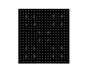
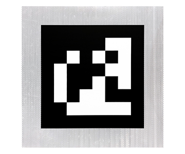
Multiple new-energy vehicle OEM testing teams reported significant calibration parameter drift due to thermal expansion/contraction-induced board deformation when using generic calibration boards in environmental cycling tests. After switching to Jingyi Optoelectronics’ chessboard calibration board, first-pass calibration yield on production lines increased by 12%, while road-test multi-sensor data alignment accuracy improved to 99.7%—substantially reducing downstream recalibration costs. As autonomous driving advances toward higher-level multi-sensor fusion and omnidirectional perception, industry demands for calibration accuracy and efficiency will continue rising. Jingyi Optoelectronics is concurrently developing next-generation calibration boards embedded with dynamic encoded identifiers—paired with AI-powered automatic recognition algorithms—to enable fully automated, one-minute calibration—boosting efficiency by 80% over current methods. This innovation is poised to become the standard tool for intelligent driving production and maintenance workflows.
#StandardCalibrationBoard #AutonomousDrivingCalibrationBoard #AutomotiveCameraCalibrationBoard #VisionRecognitionCalibrationBoard #RoboticsRecognitionCalibrationBoard #ChessboardCalibrationBoard #CalibrationBoard