Is Your Optical Power Measurement Always Inaccurate? This Comprehensive Guide—From Operation to Selection—Helps You Avoid 90% of Measurement Errors
Whether it’s construction and maintenance of optical communication networks or R&D and mass production of laser diodes and divergent light sources, the accuracy of optical power measurement directly determines the reliability of link quality assessment and product performance calibration. Yet many practitioners face issues such as “>2 dB difference between two measurements on the same device” or “completely non-referential data when measuring divergent lasers.” In reality, beyond inherent instrument performance differences, improper operation and mismatched equipment selection are the primary root causes of measurement error.
Standardized Operating Procedures for General Optical Communication Scenarios
Adhering to these key steps eliminates the vast majority of human-induced errors:
**Pre-Test Verification**
Start with pre-test verification. Beyond confirming sufficient battery power to prevent mid-test shutdown, a commonly overlooked step is cleaning the fiber optic connector interface. Dust or residue on the interface can introduce at least 0.5 dB of insertion loss—leading directly to underestimated readings. Use only dedicated lint-free fiber-cleaning wipes or alcohol swabs with ≥99% purity; never use ordinary tissue paper or clothing, which may leave behind lint or micro-scratches.
**Link Connection**
Next is link connection. Select the appropriate connector type (e.g., FC, ST, SC) matching the test fiber’s interface. Mixing connector types is strictly prohibited. Pay particular attention to the distinction between PC (physical contact) and APC (angled physical contact) polished end faces—mismatched mating introduces >1 dB of additional loss. After connection, ensure the connector is fully seated and secured. During testing, maintain a minimum bend radius of 30 mm for the fiber to avoid macro-bending losses that distort measurement results.
**Parameter Matching**
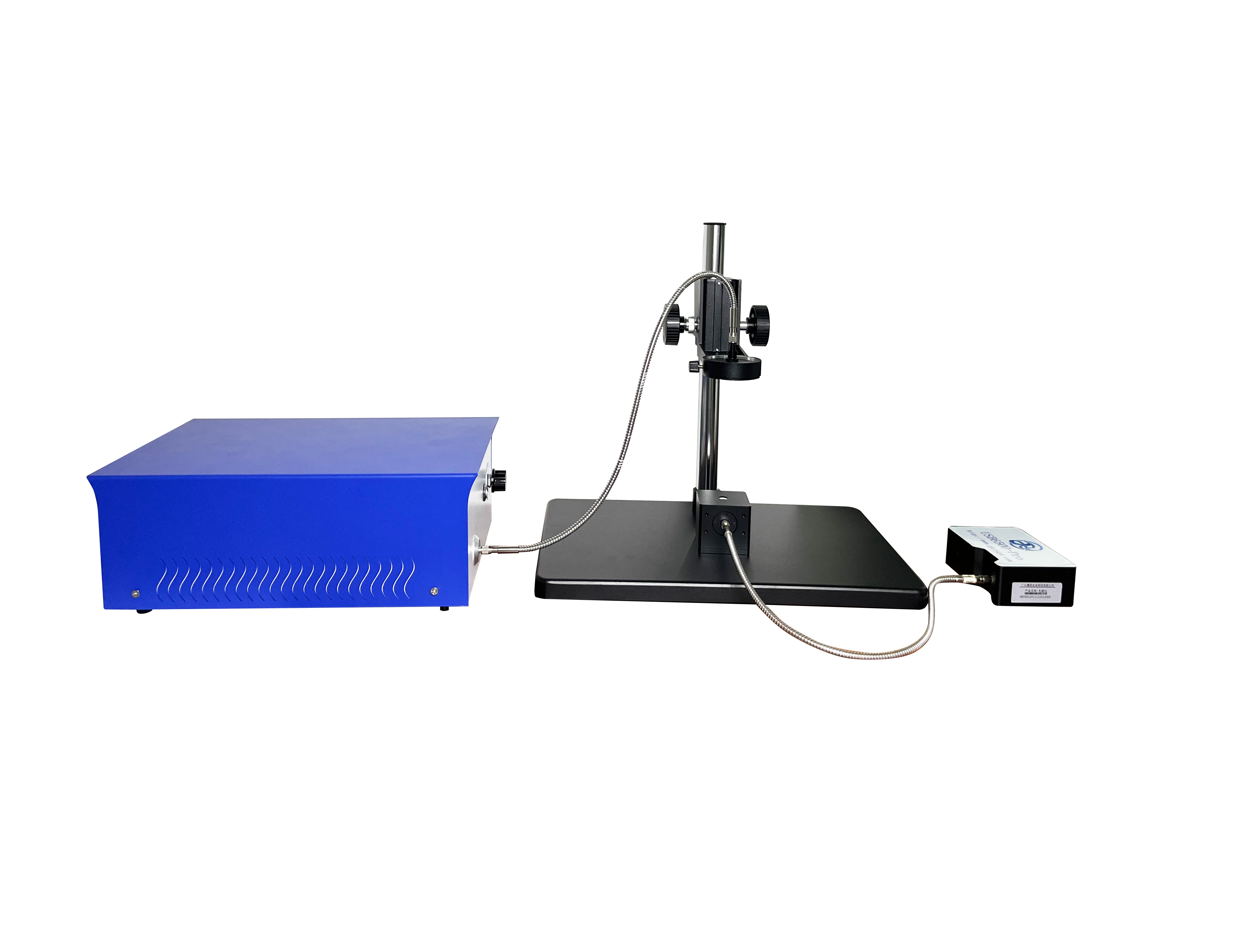
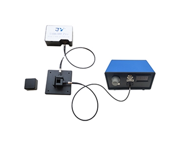
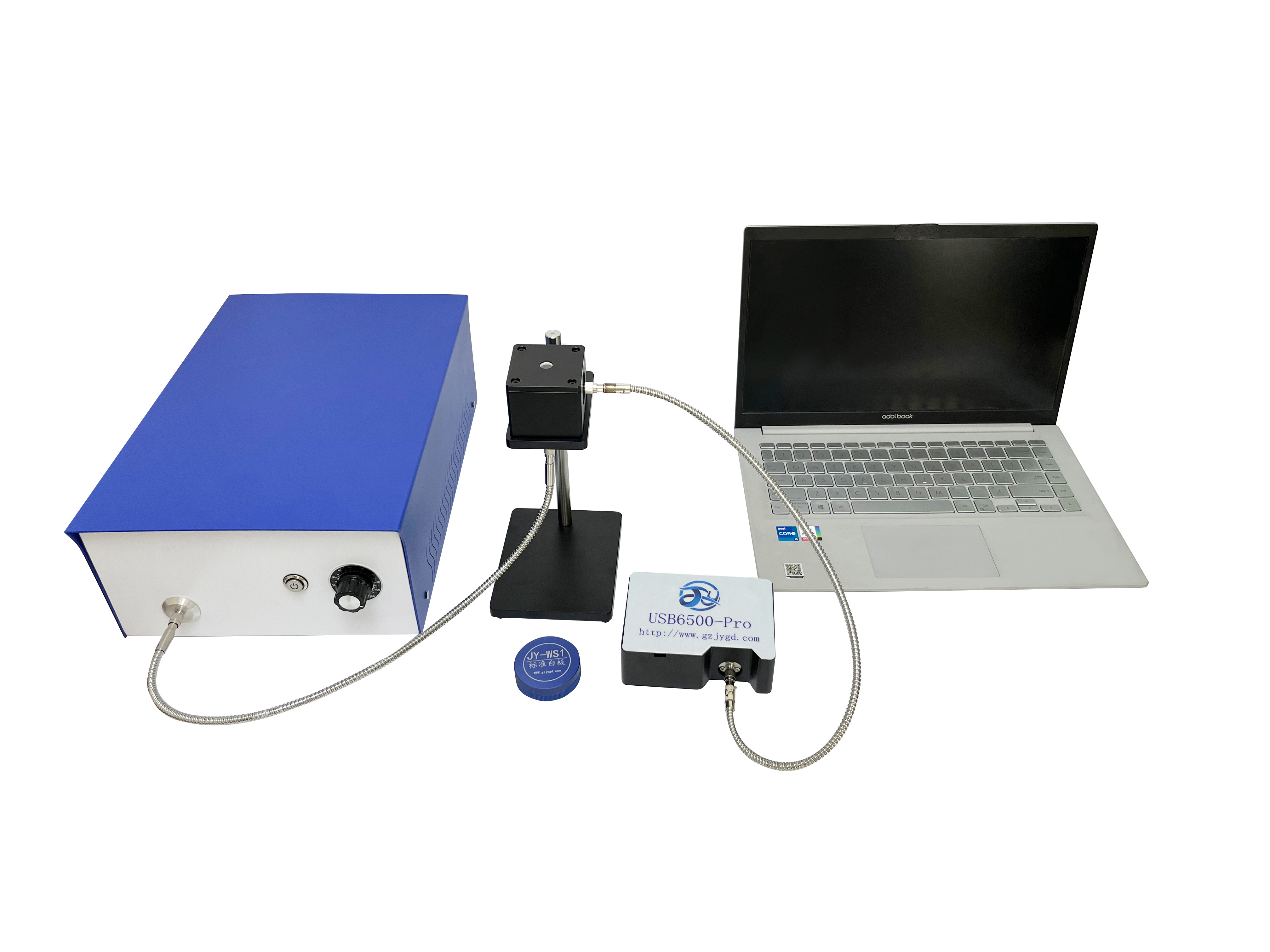
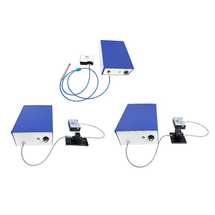
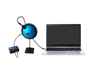
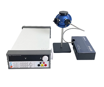
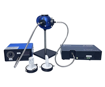
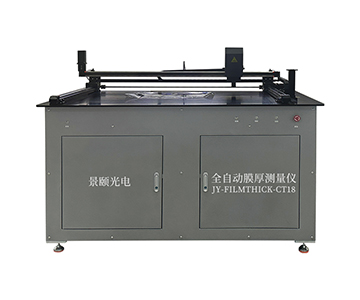
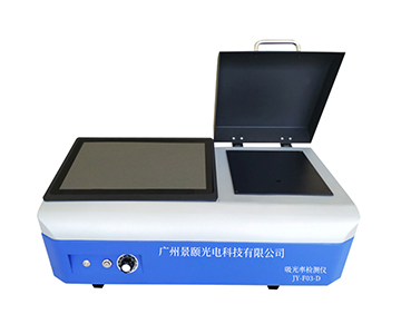
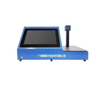
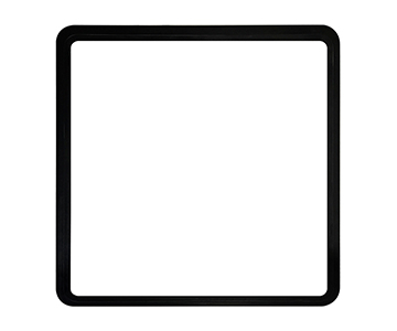
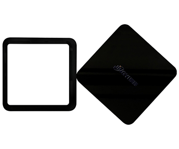
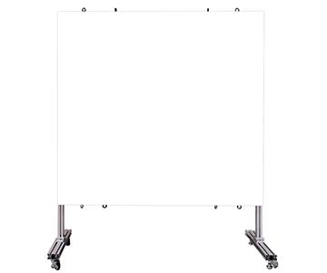
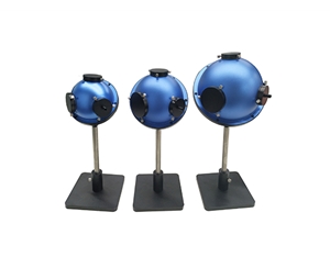
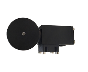
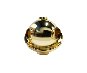
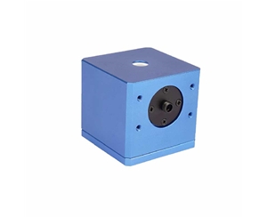
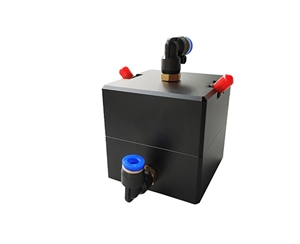
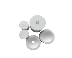
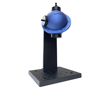
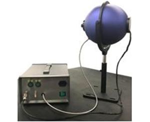
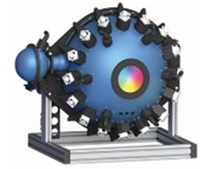
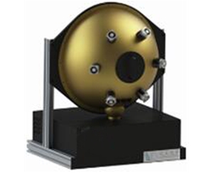
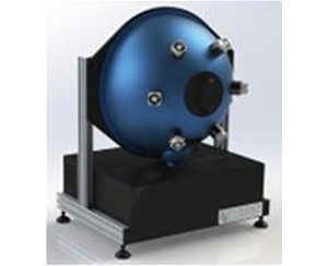
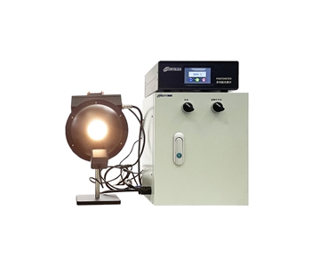
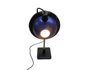
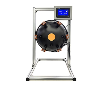
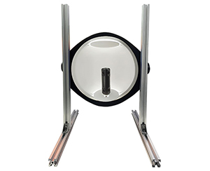
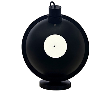
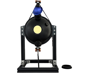
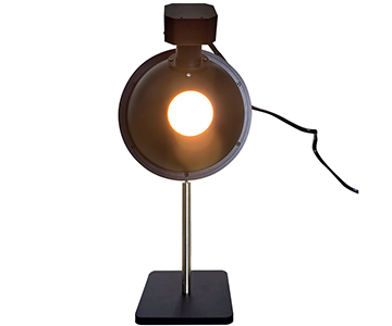
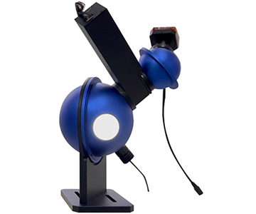
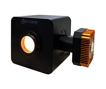
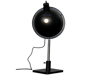
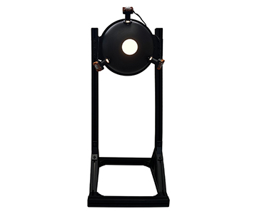
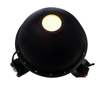
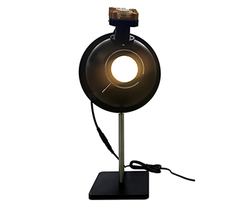
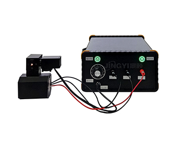
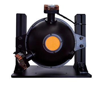
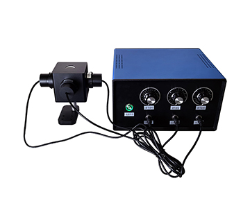
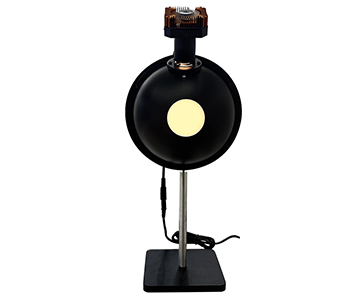
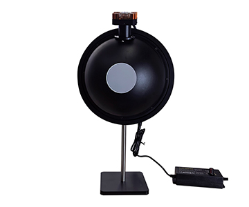
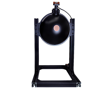
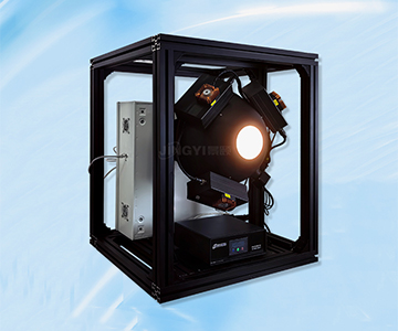
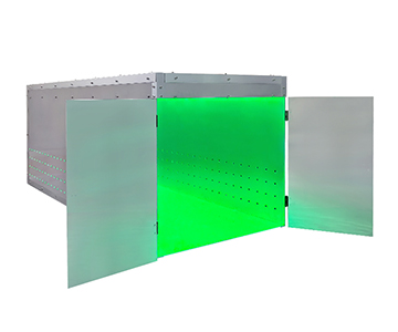
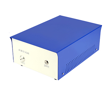
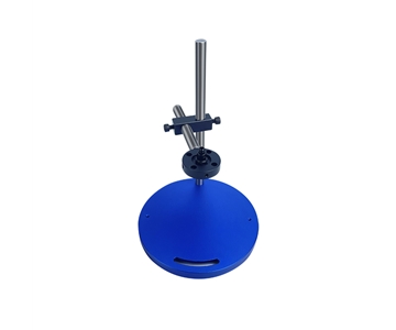
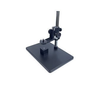
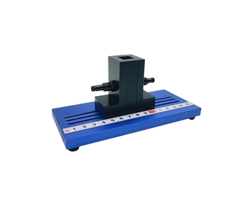
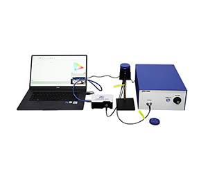
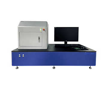
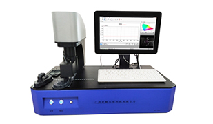
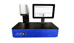
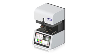
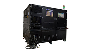
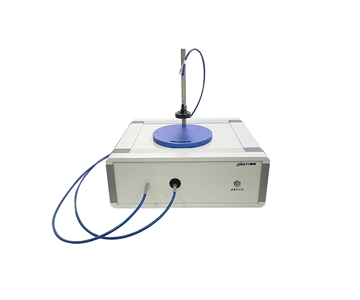
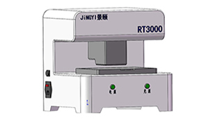
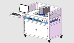
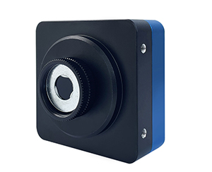
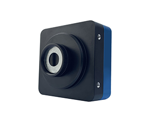
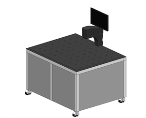
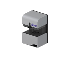
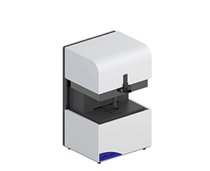
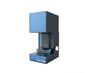
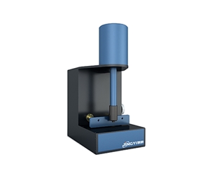
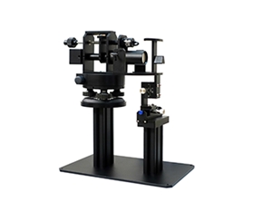
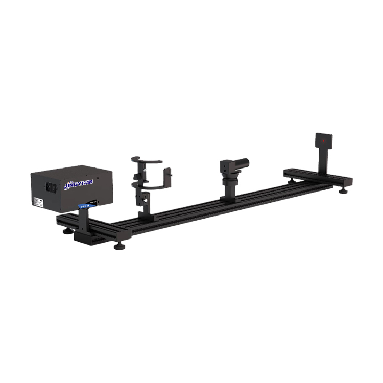
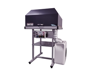
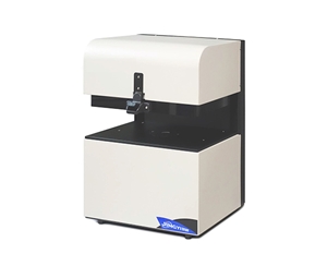
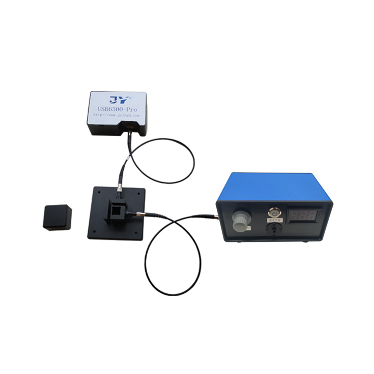
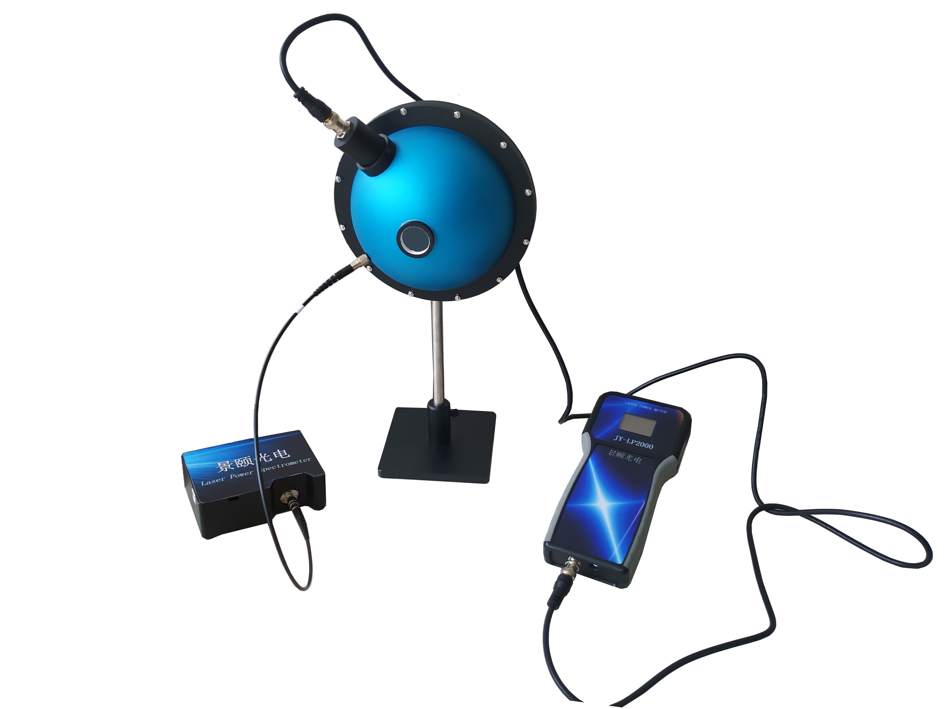
Then comes parameter matching. Even with perfectly compliant operation, conventional integrating sphere spectroradiometric power meters exhibit significant errors when measuring divergent lasers or laser diodes—due to incident angle deviation and polarization-state fluctuations. To address this industry-wide challenge, our proprietary integrating sphere spectroradiometric power test system delivers a proven solution: The entire system employs a high-diffuse-reflectance PTFE-coated integrating sphere as the light-collection cavity, whose unique geometric design fully eliminates interference from laser polarization state and incident angle variations. Coupled with a high-precision fiber-coupled spectrometer and power detection module, it simultaneously outputs both spectral characteristics and absolute power data. For high-power applications, customizable attenuation modules are available. Full system calibration is traceable to the U.S. National Institute of Standards and Technology (NIST), ensuring full compliance with the demanding accuracy requirements of laser R&D and production-line calibration. With years of deep expertise in optoelectronic metrology, all our instruments undergo multi-stage precision calibration—delivering stable, reliable test support across diverse application scenarios.
**Dynamic Testing**
Once parameters are configured, proceed to dynamic testing. For single-point link power calibration, wait until the reading stabilizes for ≥3 seconds before recording—this avoids transient source fluctuations. For long-term link stability monitoring, enable continuous measurement mode and activate averaging functions to suppress environmental noise. If ambient temperature fluctuates by more than ±5°C, perform temperature-compensation calibration prior to testing to further enhance data credibility.
**Data Review & Analysis**
Finally, conduct data review and analysis. In addition to logging real-time power values, leverage built-in statistical functions—such as max/min/average—to compare results against historical benchmarks from the same time period. A deviation >1 dB warrants immediate inspection for loose connectors or microscopic fiber bends. A deviation >3 dB relative to reference thresholds requires first checking the mating end faces for scratches or physical damage—do *not* assume fiber replacement is necessary without thorough diagnosis.
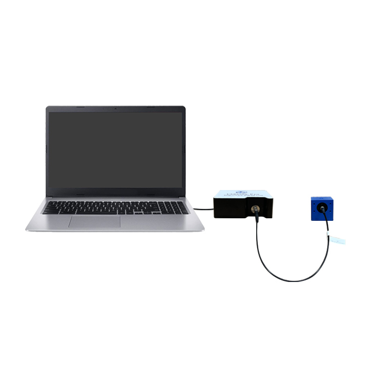
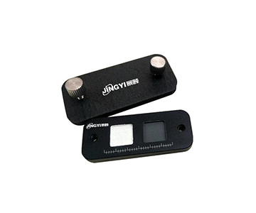
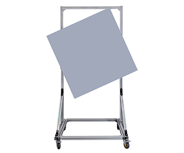
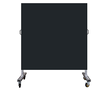
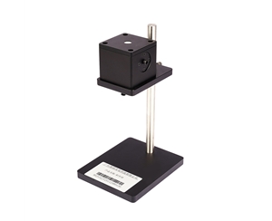
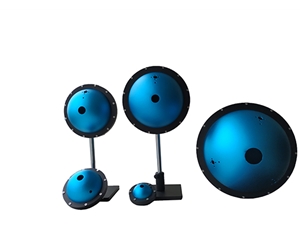
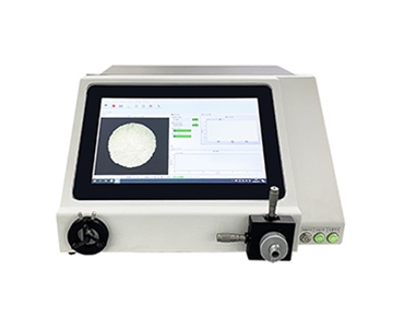
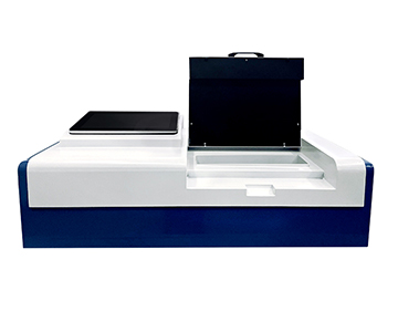
Our current portfolio spans the full range—from general-purpose portable integrating sphere spectroradiometric power meters to high-accuracy integrating sphere spectroradiometric power test systems—meeting diverse needs across optical communication operations & maintenance, laser R&D, and optoelectronic product mass-production testing. Users with customized test requirements can contact us directly for tailored solutions.
#OpticalPowerMeter #LaserPowerMeter #IntegratingSphereSpectroradiometricPowerMeter #IntegratingSphereOpticalPowerTester #LaserPowerAnalyzer #OpticalPowerAnalyzer