Comprehensive Guide to Calibrating ADAS Adaptive Cruise Control (ACC) Systems: Selecting the Right Visual Calibration Target + Following Standardized Procedures to Eliminate Perception Bias Risks
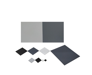
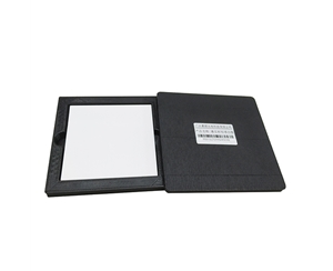
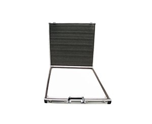
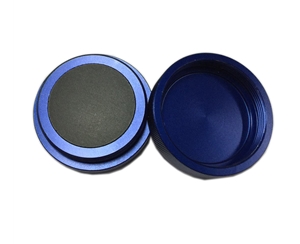
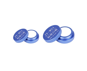
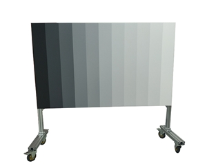
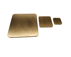
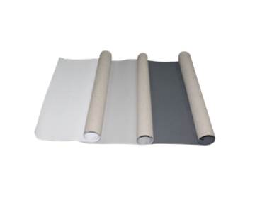
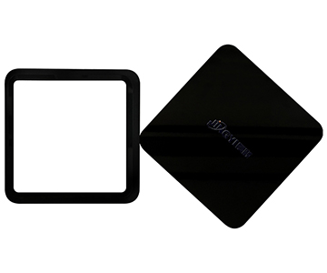
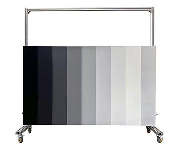
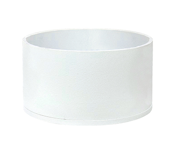
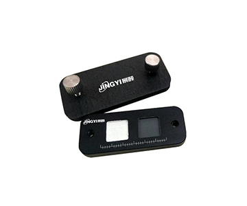
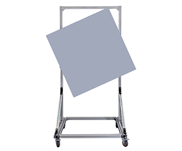
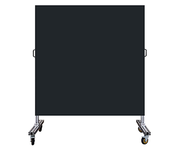
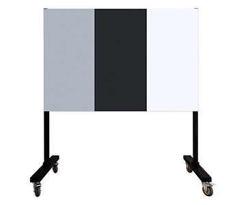
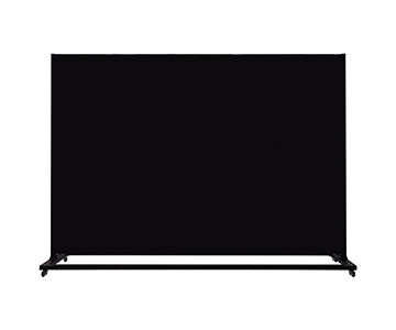
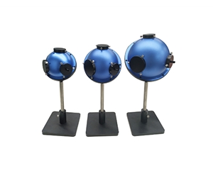
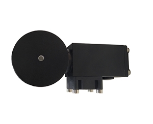
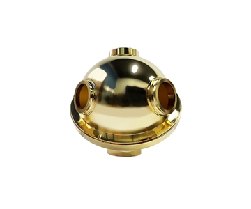
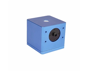
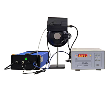
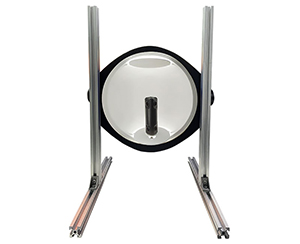
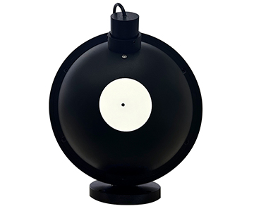
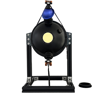
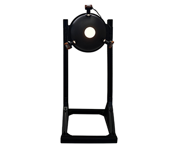
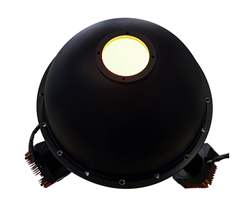
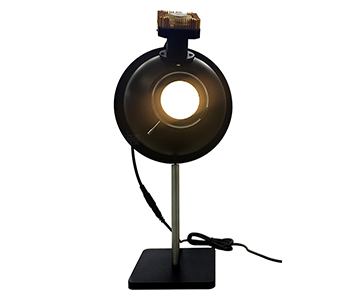
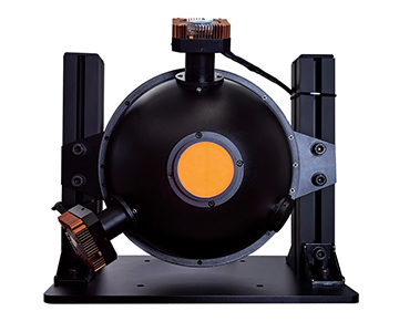
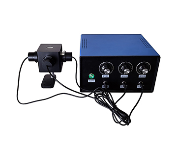
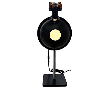
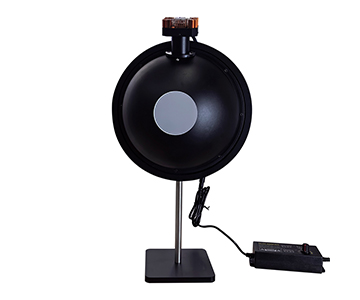
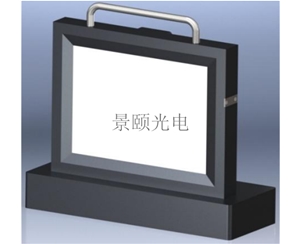
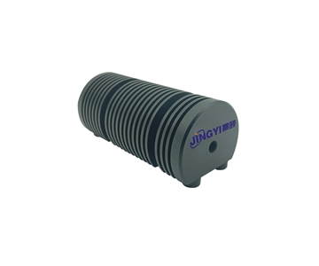
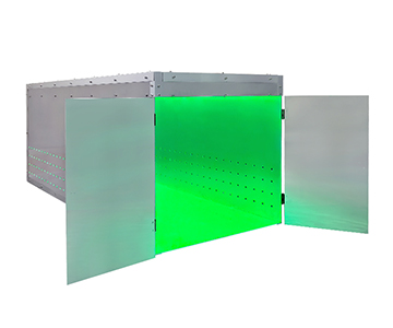
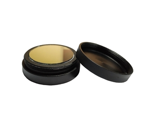
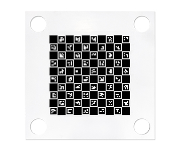
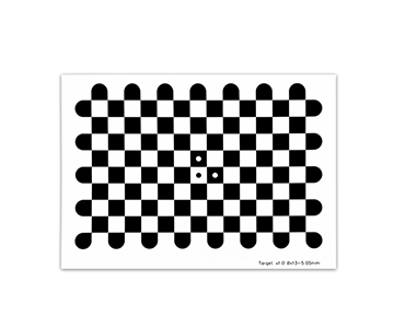
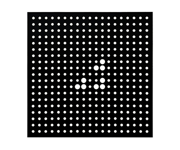
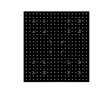
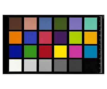
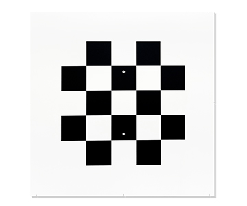
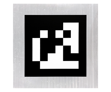
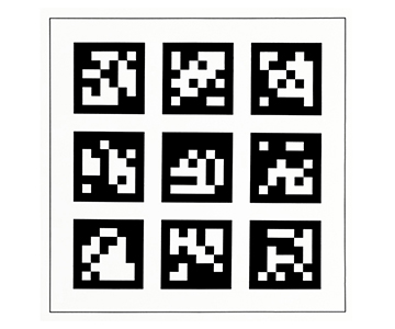
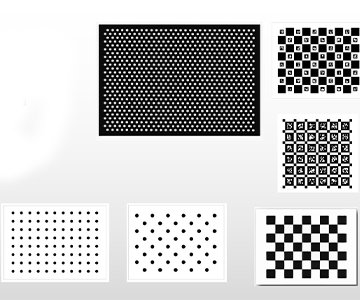
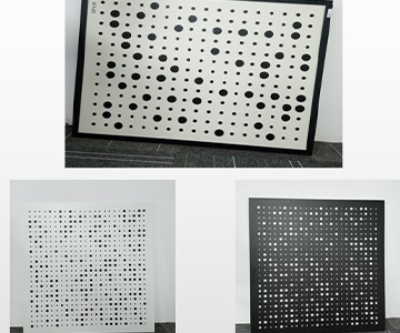
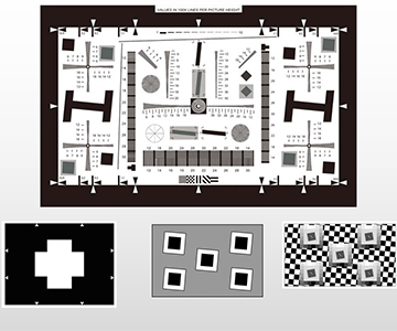
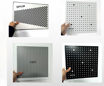
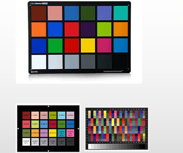
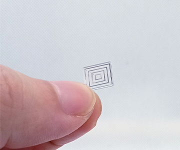
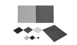
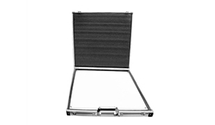
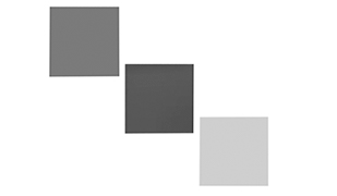
Today, intelligent driving assistance features—such as Adaptive Cruise Control (ACC) and Lane Keeping Assist—are standard on most passenger vehicles. However, when perception system warnings occur, many drivers and auto repair shops often resort to calibration using non-compliant tools or improper procedures. As a result, issues such as inaccurate following distance estimation and lane detection misalignment persist post-calibration—introducing new safety hazards. To achieve accurate calibration, the first critical step is selecting the right supporting tools from the outset: correcting camera lens distortion and establishing precise mapping between 3D physical coordinates and pixel locations demand extremely high accuracy. Jingyi Optoelectronics’ custom automotive-grade visual calibration targets deliver dimensional accuracy up to ±0.01 mm and can be tailored with pattern designs specific to individual vehicle brands. Furthermore, their diffuse reflectance panels—covering reflectivity levels from 1% to 99%—meet the stringent precision requirements for LiDAR perception calibration, resolving core tool-related challenges at the source.
Standardized Full-Calibration Operational Workflow
Pre-Calibration Site & Tool Verification
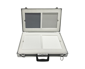
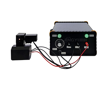
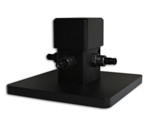
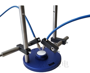
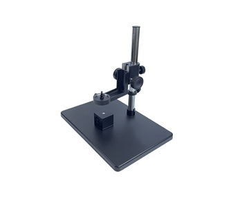
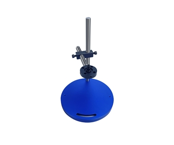
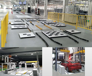
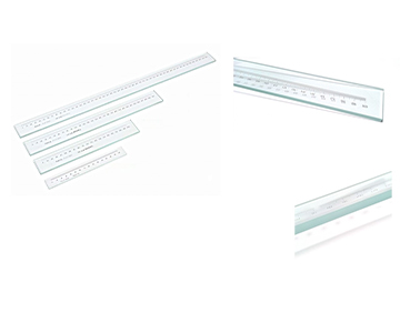
Select an open, hard-surfaced area with surface flatness deviation no greater than ±3°. Ensure no metallic obstructions or highly reflective objects exist within an 8-meter radius around the vehicle to prevent interference with radar signals and camera imaging. Required tools include: automotive-grade visual calibration targets and diffuse reflectance panels; a steel tape measure with ≥1 mm accuracy; a precision level; vehicle-specific mounting fixtures; and an OBD diagnostic device.
ACC Radar Calibration Procedure
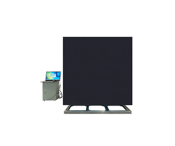
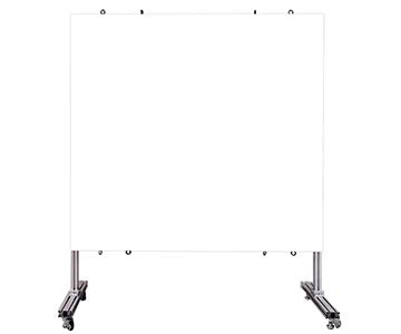
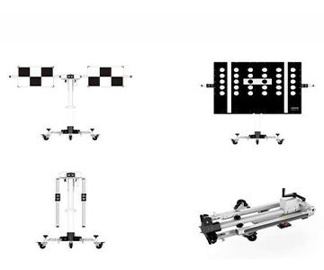
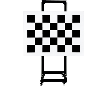
Follow the vehicle manufacturer’s official specifications to determine the required visual calibration target placement distance. Most mainstream models employ either a 5-meter or 10-meter calibration distance. All measurements must reference the geometric center point of the vehicle’s front bumper. After positioning, clearly mark this point on the ground. Mount the visual calibration target onto its dedicated fixture at the marked location, then use the level to adjust the fixture’s verticality—ensuring the target plane is perfectly perpendicular to the vehicle’s forward direction, and that the target’s geometric center aligns precisely with the vehicle’s longitudinal centerline (tolerance ≤1 cm). Once secured, power on the vehicle and enter diagnostic mode, then follow the OEM-provided calibration sequence to complete the procedure.
Onboard Camera Calibration Procedure
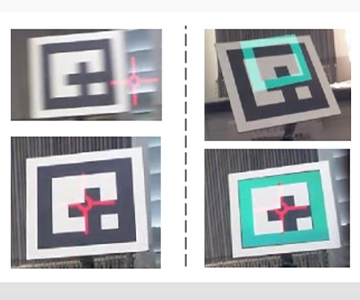
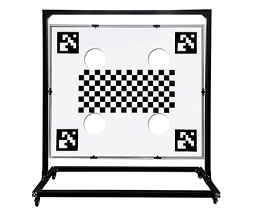
Camera calibration typically requires a 7-meter target distance—again measured from the front bumper’s geometric center. In addition to ensuring the visual calibration target is vertically aligned and centered on the vehicle’s longitudinal axis, verify that the full pattern area falls entirely within the camera’s field of view, with no cropping at the edges. After finalizing position adjustments, connect the diagnostic system and follow on-screen prompts to complete feature-point recognition and parameter programming.
Closed-Loop Calibration for Fault Alarms
If the vehicle triggers an ACC system fault warning, do *not* initiate calibration immediately. First, inspect the radar sensor surface for snow accumulation, mud, or adhesive film—and examine the camera lens for scratches or fogging. Only after ruling out physical hardware damage should you connect the OBD diagnostic tool to retrieve and clear stored fault codes. Then, re-perform dual-component calibration for both radar and camera according to the procedures outlined above. Post-calibration, conduct real-road validation: test following-distance responsiveness and lane-detection accuracy at three speed tiers—30 km/h, 60 km/h, and 90 km/h. Only after confirming no perception anomalies across all tests is the full process considered complete.
The perception accuracy of intelligent driving assistance systems directly impacts driving safety. From selecting the appropriate visual calibration target to executing every step of the operational workflow with rigor—no detail can be overlooked. Jingyi Optoelectronics’ automotive-grade visual calibration targets and diffuse reflectance panels serve the full spectrum of calibration needs—from individual car owners to professional repair facilities—providing foundational assurance for precise perception-system calibration.
#VisualCalibration #VisualCalibrationTarget #DotPatternCalibrationTarget #VisionRecognitionCalibrationTarget #PortableCalibrationTarget #QRCodeCalibrationTarget #CalibrationTarget