Thin Film Thickness Measurement Techniques and Applications
In today’s era of rapid technological advancement, thin-film technology has found extensive application across high-end sectors—including semiconductors, microelectronics, optics, displays, new energy, automotive, and aerospace industries. Precise measurement of thin-film thickness is a critical factor in ensuring product quality, controlling manufacturing costs, and driving technological innovation. For instance:
- In integrated circuit fabrication, the accuracy of photoresist and dielectric layer thickness directly affects chip performance and functionality;
- In MEMS devices, functional film thickness determines sensing precision and operational stability;
- Optimizing the thickness of anti-reflection coatings on photovoltaic cells significantly enhances photoelectric conversion efficiency;
- In perovskite solar cells, the thickness of functional layers directly governs energy output.
Clearly, thin-film thickness measurement holds indispensable importance across diverse industries.
So how does one select the most suitable technique or instrument from the wide array of available options? This requires an in-depth understanding of the underlying measurement principles and their respective applicability domains.
**Principles of Thin-Film Thickness Measurement and Industry Applications**
**Spectral Reflectance / Optical Interferometry**
*Principle*
Optical interferometry leverages the wave nature of light. When incident light strikes a thin film surface, part reflects at the air–film interface, while another portion transmits into the film and reflects at the film–substrate interface. These two reflected beams interfere with each other. By precisely analyzing this interference pattern—combined with spectral reflectance data and known material refractive indices—the film thickness can be accurately determined.
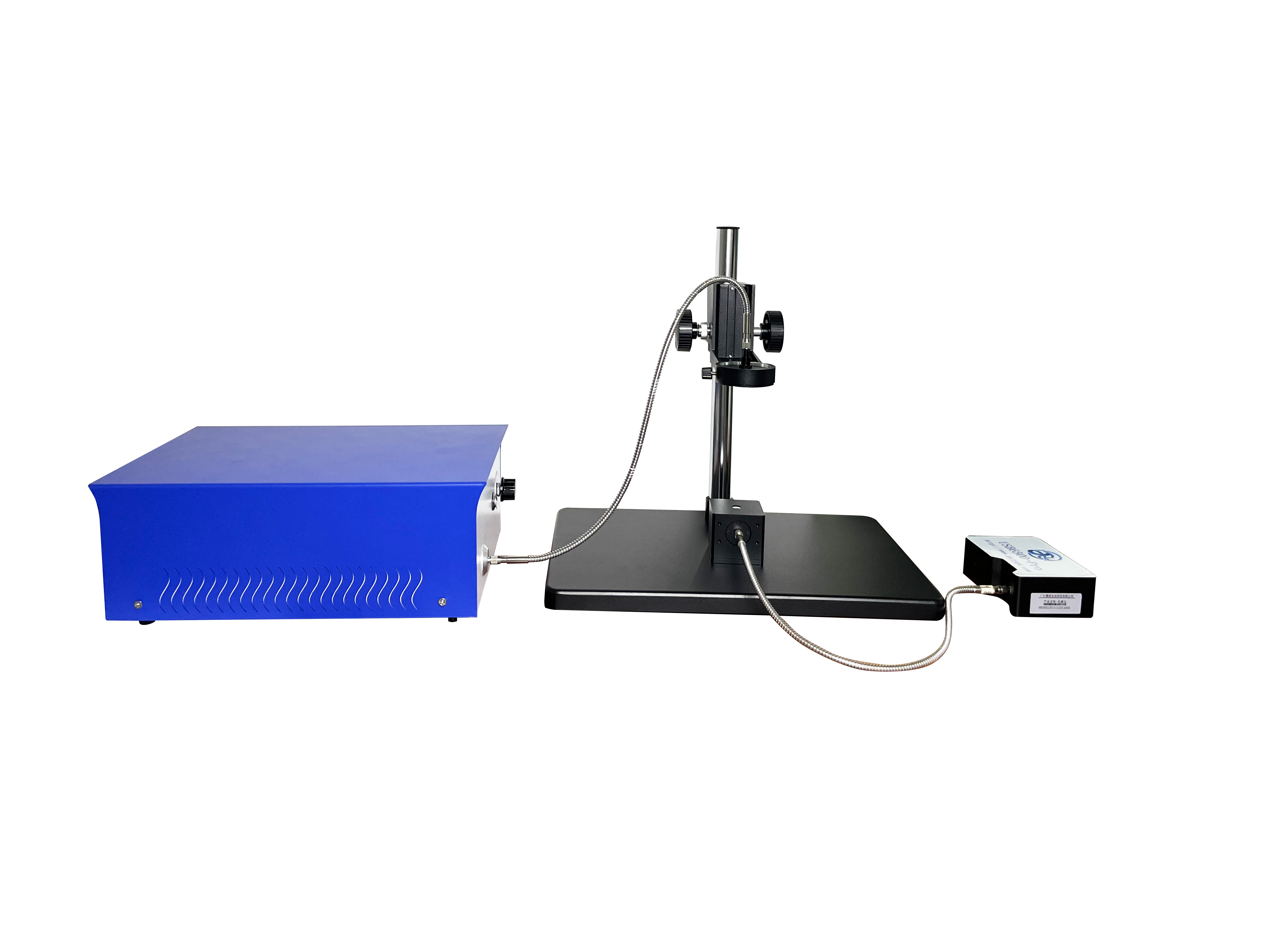
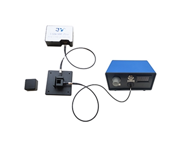
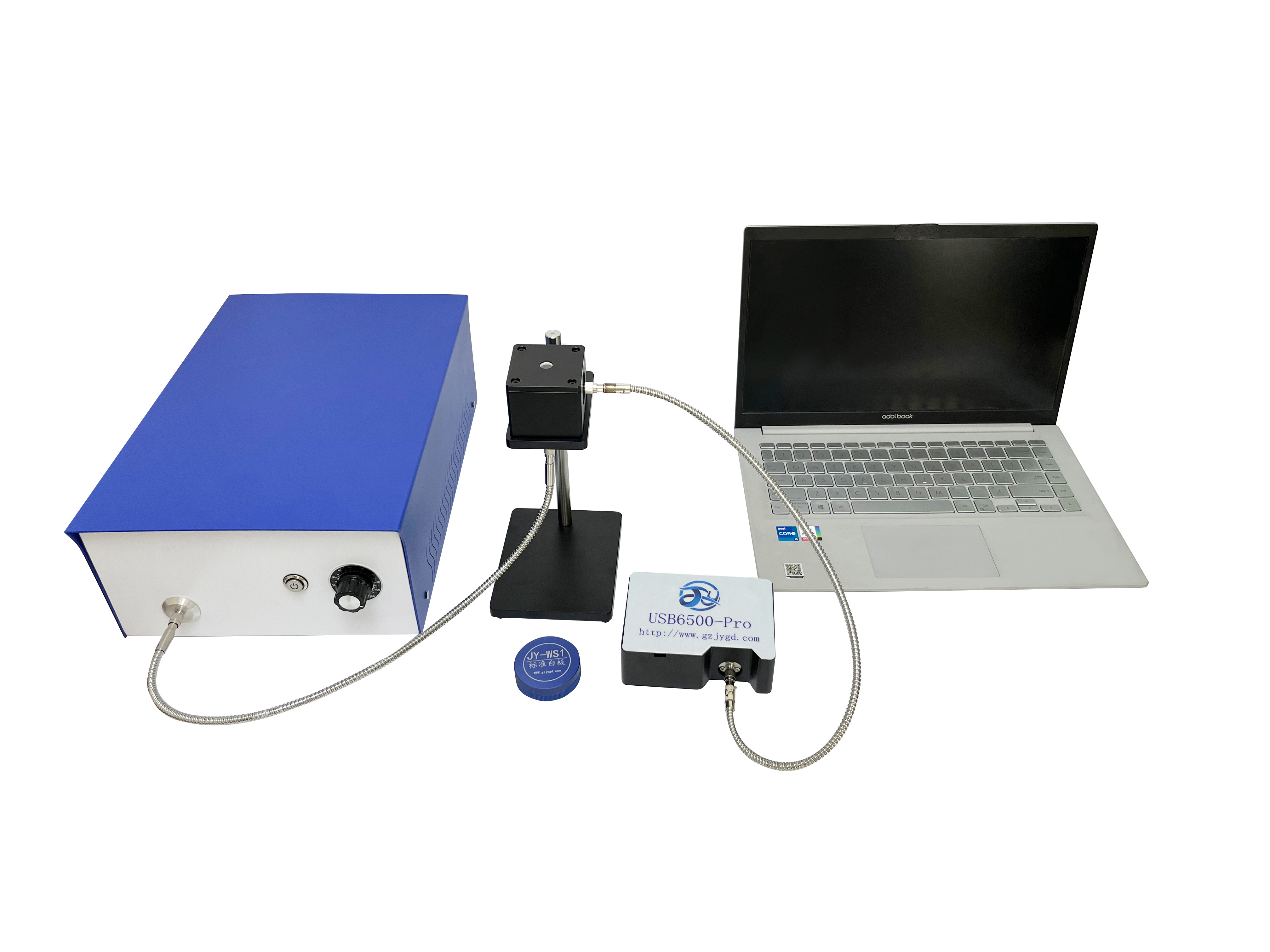
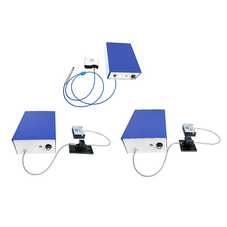
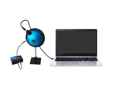
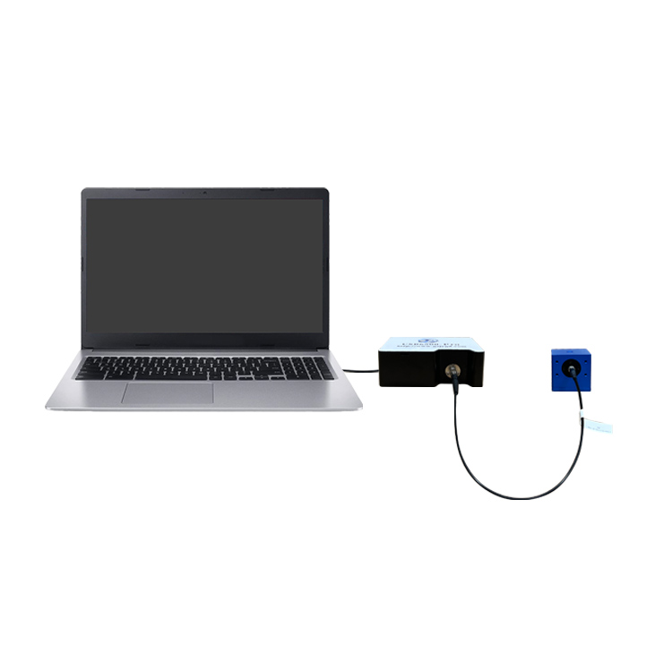
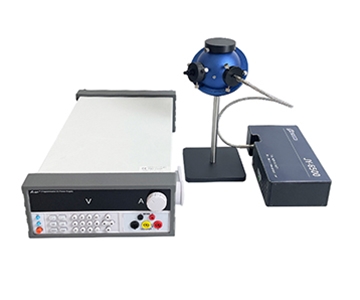
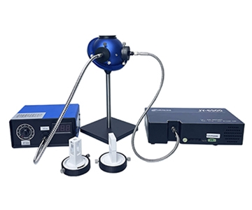
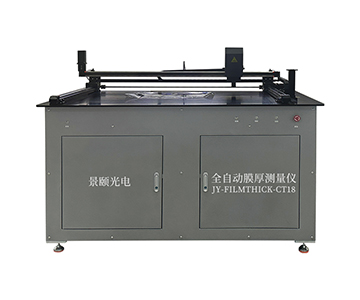
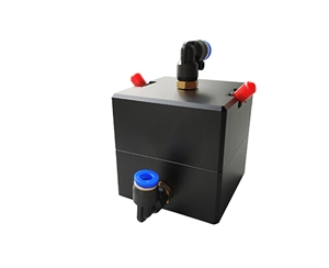
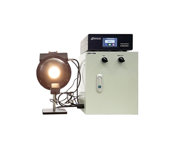
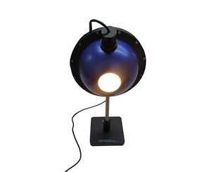
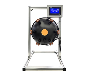
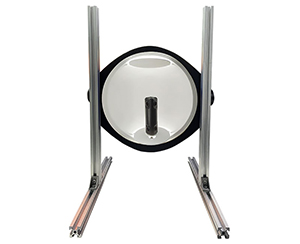
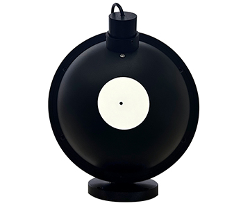
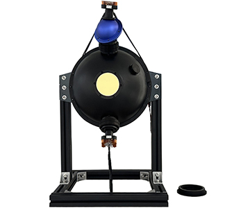
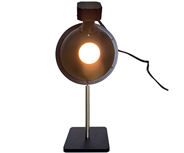
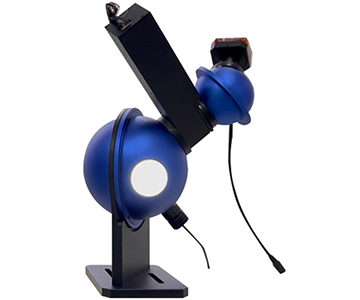
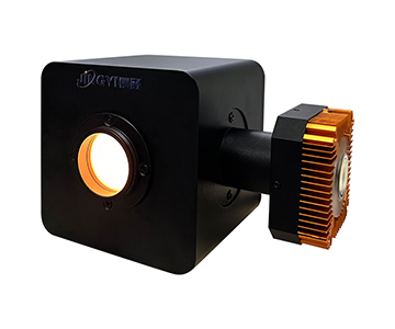
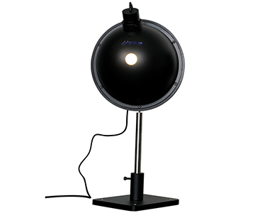
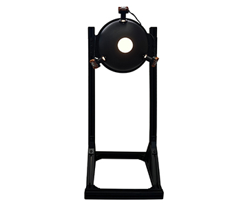
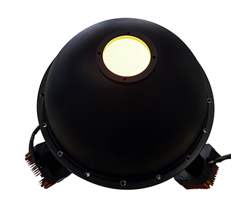
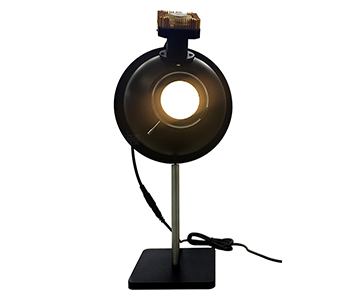
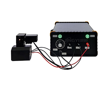
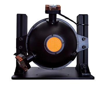
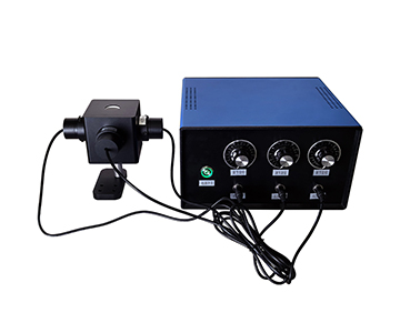
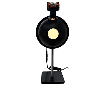
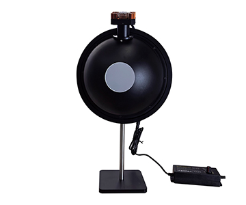
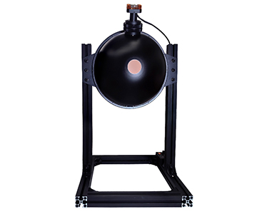
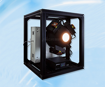
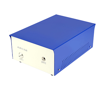
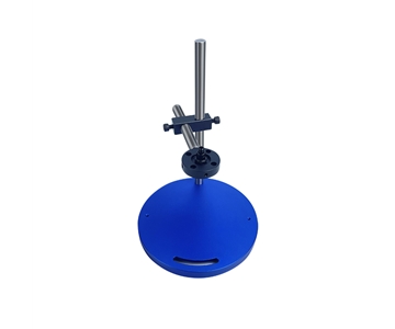
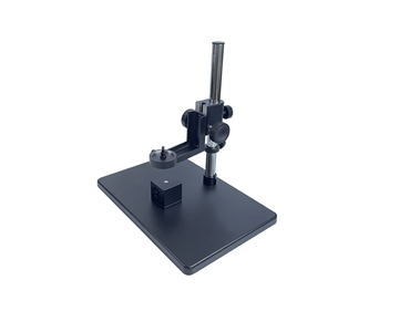
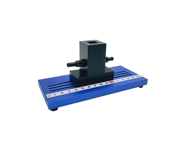
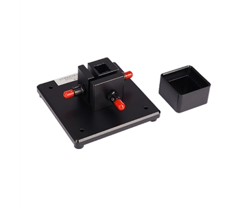
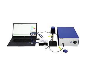
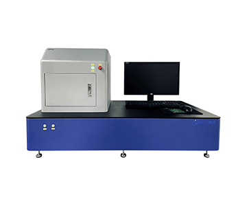
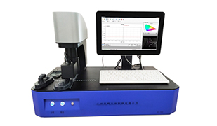
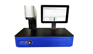
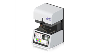
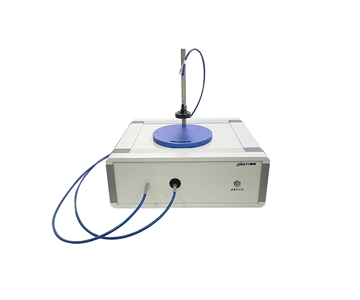
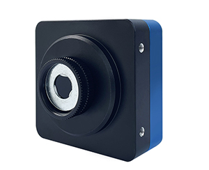
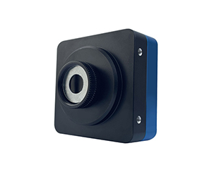
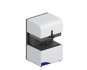
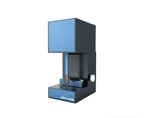
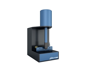
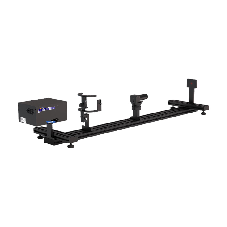
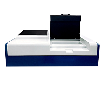
For example, Jingyi Optoelectronics’ FILMTHICK_C10 thin-film thickness meter employs optical interferometry. Its mechanical design integrates a high-lifetime imported halogen-tungsten light source (>10,000 hours), enabling non-contact, non-destructive, and highly accurate measurements of parameters including reflectance, color, and film thickness. The accompanying OPTICAFILMTEST optical film-thickness measurement software implements multiple high-precision algorithms—including Fast Fourier Transform (FFT), extremum detection, and curve fitting—as well as comprehensive built-in and user-expandable refractive index databases. Real-time visualization of interference patterns, FFT spectra, and thickness trends during measurement provides robust support for both R&D and production environments.
*Applicable Scenarios*
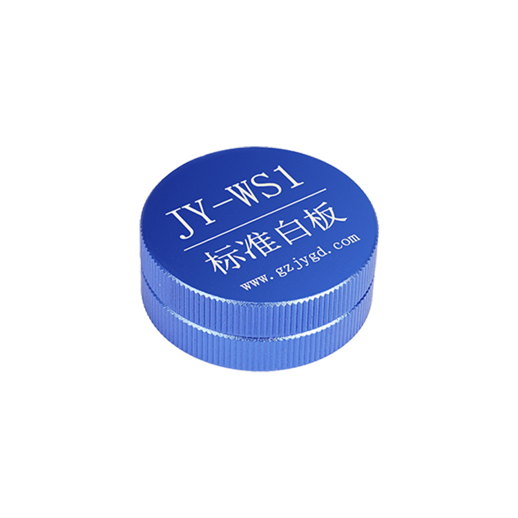
This method is ideal for measuring transparent or semi-transparent thin films—including semiconductor photoresists, LCD alignment layers, optical coatings, and quantum dots—with a measurable thickness range spanning 1 nm to 250 µm. Notably, although optical interference fundamentally applies only to transparent/semi-transparent materials, extremely thin metallic films—down to just a few nanometers—can still permit partial light transmission; under such conditions, precise thickness determination remains feasible via this principle.
**Magnetic Induction Method**
*Principle*
The magnetic induction method exploits the change in magnetic reluctance caused by a non-magnetic coating on a ferromagnetic substrate. As the probe approaches the coated ferromagnetic surface, the coating alters the magnetic flux path between probe and substrate, resulting in a measurable change in magnetic reluctance. Calibration and calculation based on this change yield the coating thickness.
*Applicable Scenarios*
Primarily used for measuring non-magnetic coatings on ferromagnetic substrates—e.g., corrosion-protection coatings on steel structures. Accurate thickness measurement here is essential for guaranteeing corrosion resistance and surface finish quality.
**Eddy Current Method**
*Principle*
The eddy current method relies on electromagnetic induction: a high-frequency alternating current passing through a coil generates an oscillating magnetic field. When this coil is brought near a conductive metal substrate covered with a non-conductive coating, eddy currents are induced in the substrate. The presence of the insulating coating modifies both the spatial distribution and feedback signal of these eddy currents. By detecting and analyzing such modifications, coating thickness can be derived.
*Applicable Scenarios*
Commonly applied to non-conductive coatings on electrically conductive metallic substrates—e.g., aircraft exterior coatings or aluminum oxide films. In aerospace applications, where flight safety and reliability depend critically on precise coating control, the eddy current method delivers reliable, non-contact, and rapid measurement capabilities.
**X-ray Fluorescence (XRF) Method**
*Principle*
The XRF method irradiates the sample with X-rays, exciting characteristic fluorescent radiation from constituent elements. Each element emits fluorescence at specific energies and intensities. Analyzing these spectral features enables quantitative determination of both composition and thickness of plated layers. Grounded in X-ray absorption and fluorescence emission physics, this technique offers high accuracy and sensitivity.
*Applicable Scenarios*
Especially suited for non-destructive analysis of multi-layer or compositionally complex coatings—such as electronic component platings and alloy-based coatings. As electronics continue shrinking and integrating further, demand for precise, high-resolution thickness and compositional metrology is growing steadily. XRF meets this need, providing a dependable technical foundation for quality assurance in electronics manufacturing.
**Ultrasonic Thickness Measurement**
*Principle*
Ultrasonic thickness measurement utilizes acoustic impedance mismatch at material interfaces: when ultrasonic waves emitted from a transducer reach a coating–substrate interface, a portion reflects back. By measuring the time-of-flight difference between echoes and incorporating known sound velocities in both coating and substrate materials, coating thickness can be calculated.
*Applicable Scenarios*
Suitable for multi-layer coatings or situations where magnetic or eddy-current methods fail. However, domestic adoption remains relatively limited—likely due to higher equipment costs and lower market penetration. Still, niche applications exist—e.g., integrity inspection of corrosion-protection coatings on large-scale industrial equipment—where ultrasonic methods hold promising potential.
**Electrolytic Thickness Measurement**
*Principle*
Electrolytic thickness measurement involves controlled electrochemical dissolution of the coating. Based on the linear relationship between consumed charge (current × time) and removed coating volume, thickness is deduced by monitoring electrolytic current consumption and applying appropriate calibration factors. This is a destructive technique causing localized sample damage.
*Applicable Scenarios*
Mainly employed in laboratory settings for lower-precision coating analyses. Where sample quantity is limited or measurement requirements are modest—e.g., basic research—it serves as a simple and effective analytical tool.
**Radioisotope (Beta/Gamma) Thickness Gauging**
*Principle*
Radioisotope gauging measures thickness by quantifying the attenuation of particles (e.g., beta or gamma rays) emitted from a radioactive source as they traverse the coating. Particle intensity diminishes due to interactions with coating atoms. By comparing incident and transmitted intensities—and applying established attenuation models—the coating thickness is computed.
*Applicable Scenarios*
Deployed in extreme industrial environments requiring thickness monitoring under high temperature, high pressure, or other harsh conditions. However, regulatory constraints related to radiation safety, coupled with high instrumentation costs, significantly limit its widespread use.
**Measurement Techniques and Applications Across Thickness Scales**
**Nanoscale (1 nm – 100 nm)**
*Techniques*
Common techniques include spectroscopic ellipsometry, high-precision spectrally resolved interferometric film thickness meters (e.g., Jingyi Optoelectronics’ FILMTHICK_C10), and white-light interferometry (e.g., Atometrics AM series). All deliver sub-nanometer resolution suitable for demanding nanoscale metrology.
*Applications*
Key areas include semiconductor thin films (e.g., silicon nitride, photoresist), perovskites, and quantum dots. In semiconductor fabrication, nanoscale thickness control is vital for chip performance and reliability:
- Silicon nitride film thickness directly influences gate insulation strength and capacitance;
- Photoresist uniformity and dimensional accuracy govern lithographic resolution and pattern transfer fidelity.
**Sub-Micron Scale (100 nm – 1 µm)**
*Techniques*
High-precision spectrally resolved interferometers (e.g., FILMTHICK_C10) and white-light interferometers (e.g., Atometrics AM series) remain widely adopted—balancing nanoscale accuracy with enhanced throughput and stability required for inline process control.
*Applications*
Predominantly used in optical coatings and MEMS device films. Precise thickness tuning is essential for achieving targeted optical functions—e.g., anti-reflection, high reflection, or spectral filtering. For instance, multilayer optical coatings on camera lenses require strict control over individual layer thicknesses to maximize light transmission and imaging clarity.
**Micron Scale (1 µm – 100 µm)**
*Techniques*
Diverse methodologies apply—including magnetic induction, eddy current, and spectrally resolved interferometry (e.g., FILMTHICK_C10). Selection depends on substrate type, coating conductivity, and operational constraints.
*Applications*
Widely deployed for industrial corrosion-protection coatings and printed circuit board (PCB) plating. Accurate thickness measurement ensures adequate corrosion resistance and service life: e.g., protective coatings on structural steel must conform to minimum thickness specifications to sustain long-term integrity in aggressive environmental conditions.
**Millimeter Scale (>100 µm)**
*Techniques*
Conventional methods include ultrasonic thickness gauging, spectrally resolved interferometry (e.g., FILMTHICK_C10), and spectral confocal technology (e.g., Atometrics AP-5000 series). These offer broad dynamic range, high repeatability, and excellent reliability for thick-film applications.
*Applications*
Critical for thick coatings and composite materials. Examples include automotive body primers and topcoats—often hundreds of microns to millimeters thick—where thickness uniformity directly impacts aesthetics, durability, and corrosion resistance. In composites, precise thickness assessment supports evaluation of structural integrity, interfacial bonding, and overall quality assurance.
Integrating considerations of both physical measurement principles *and* thickness scale enables dramatic narrowing of candidate instruments for any given measurement task. Beyond this, users must weigh additional practical criteria—including measurement accuracy, speed, reproducibility, ease of operation, sample compatibility, and total cost of ownership—to make a holistic, evidence-based selection. Only through such rigorous evaluation can optimal thin-film thickness measurement strategies be implemented—ensuring precision, consistency, and value across R&D, manufacturing, and quality assurance workflows.
#FilmThicknessGauge #FilmThicknessAnalyzer #ThicknessGauge #FilmThicknessMeter #FilmThicknessTester #CoatingThicknessGauge #FilmThicknessInstrument