In the field of optical material research and application, transmittance—defined as a key parameter for evaluating a material’s ability to transmit light—holds significant importance. It not only directly affects the performance of materials within optical systems but also serves as a critical basis for material development, quality control, and application selection. Below, we will delve into the principles, methodologies, influencing factors, and essential considerations associated with transmittance measurement.
**The Nature and Significance of Transmittance**
From a physics perspective, transmittance is defined as the percentage ratio of the transmitted luminous flux (\(\Phi_t\)) to the incident luminous flux (\(\Phi_0\)), expressed by the formula:
\[
\text{Transmittance (\%)} = \frac{\Phi_t}{\Phi_0} \times 100\%
\]
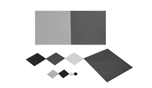
This metric accurately reflects a material’s capacity to transmit light. Due to differences in molecular structure, chemical composition, and other intrinsic factors, various materials exhibit distinct transmittance characteristics. For instance, common materials such as glass, plastics, and thin films each possess unique transmittance ranges—determining their suitability for specific applications across diverse fields.
**Primary Methods and Standards for Transmittance Measurement**
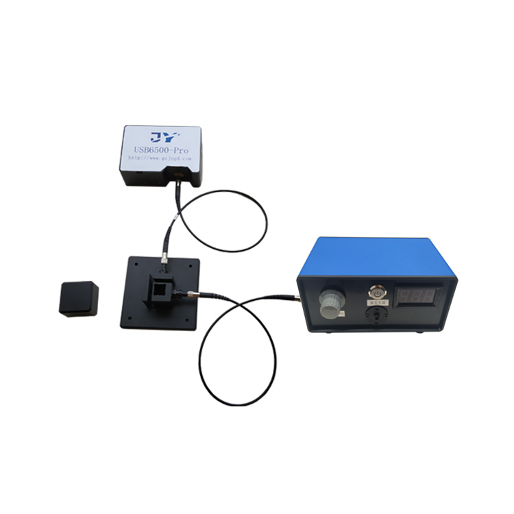
**Ultraviolet–Visible (UV–Vis) Spectrophotometry**
*Applicability*
This method is suitable for transparent or semi-transparent materials, including glass, plastic films, and optical lenses.
*Reference Standards*
Domestic standards include GB/T 2410–2008 *Determination of Luminous Transmittance and Haze of Transparent Plastics*. International standards include ASTM D1003–13 *Standard Test Method for Haze and Luminous Transmittance of Transparent Plastics*.
*Procedure*
- **Instrument Calibration**:
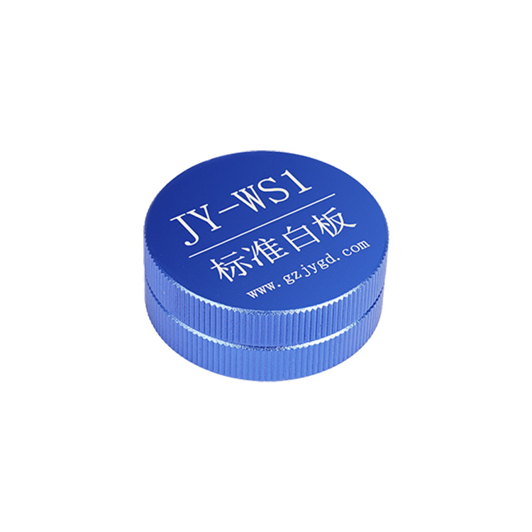
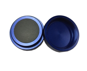
Power on the instrument and allow it to warm up for at least 30 minutes to ensure stable operation. Calibrate “100% transmittance” using ambient air (or a standard white reference tile), and “0% transmittance” using a black body (light trap).
- **Selection of Measurement Wavelength**:
Choose an appropriate wavelength based on material properties and testing requirements—e.g., 550 nm, the peak sensitivity wavelength in the visible spectrum.
- **Sample Preparation**:
Samples must be flat, bubble-free, and scratch-free, with dimensions conforming to the instrument’s cuvette or sample holder specifications—typically uniform-thickness planar specimens. For liquid samples, carefully fill the cuvette without introducing air bubbles.
- **Measurement Process**:
Place the prepared sample into the sample compartment; the instrument automatically measures and displays the transmittance value. For non-uniform materials, perform at least three measurements at different positions and calculate the average to ensure accuracy.
- **Data Recording**:
Record transmittance values along with corresponding wavelengths, sample thicknesses, and other relevant parameters for subsequent analysis and comparison.
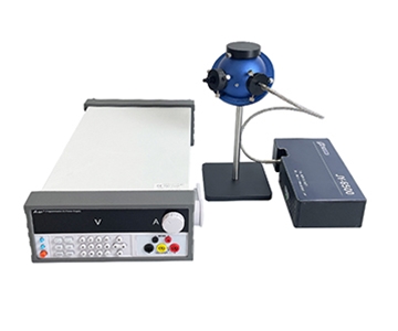
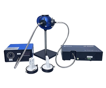
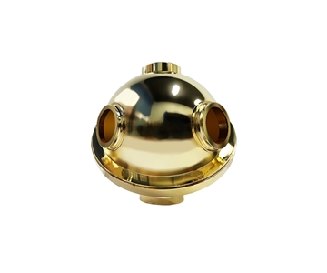
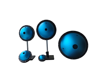
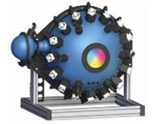
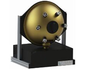
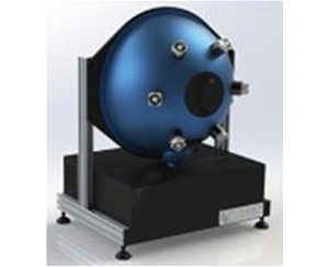
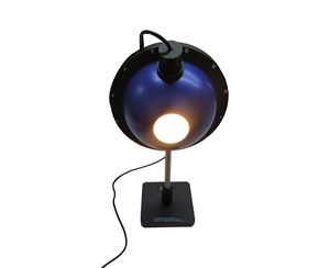
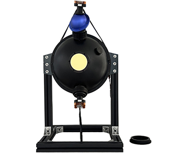
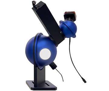
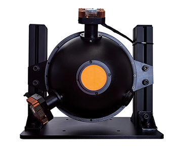
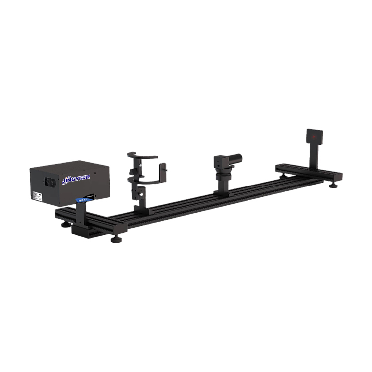
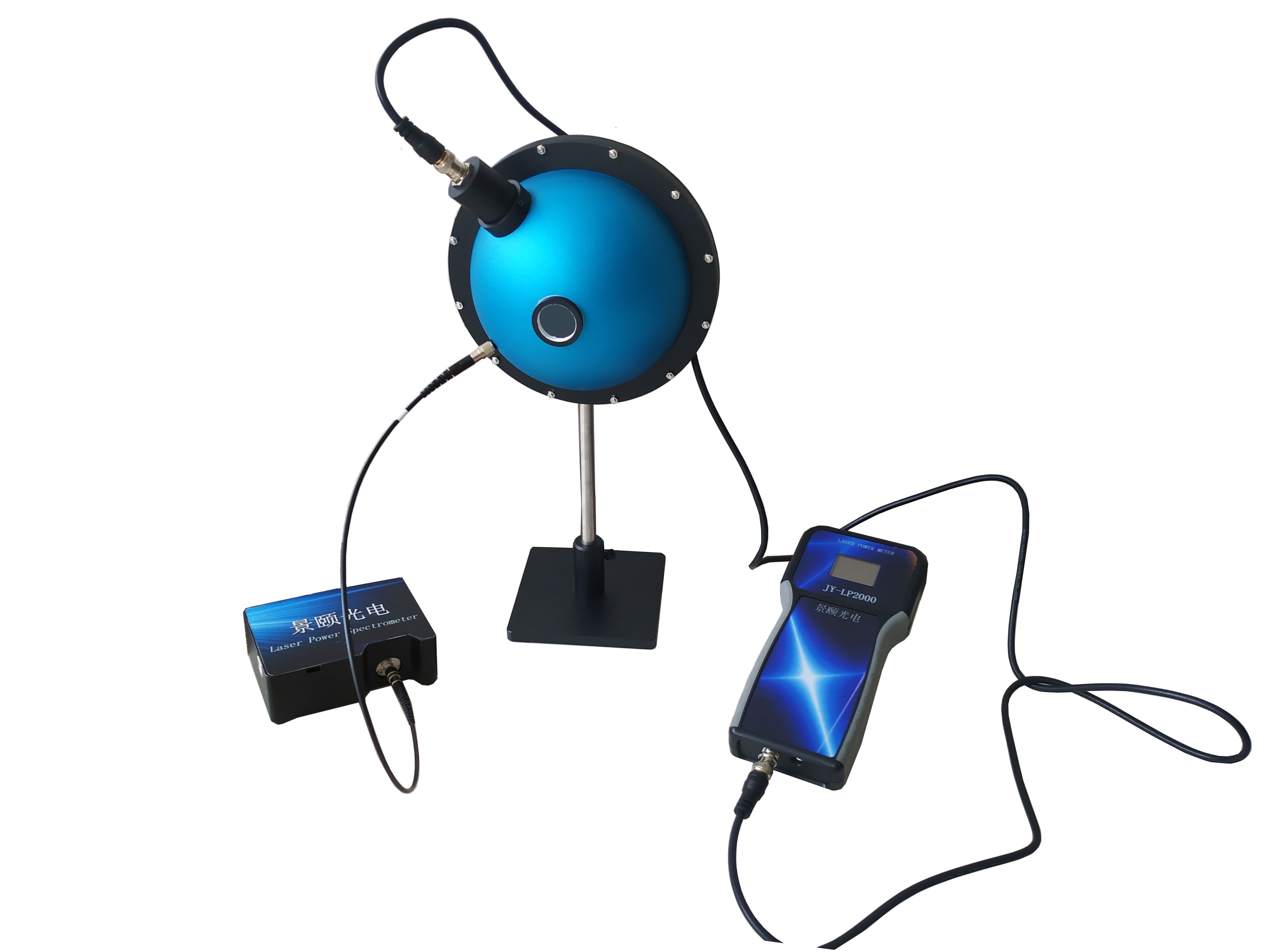
**Transmittance Meter Method (Integrating Sphere Method)**
*Applicability*
Suitable for transparent, semi-transparent, or diffusely transmitting materials—such as frosted glass and milky plastics—and particularly advantageous for full-spectrum transmittance measurement.
*Reference Standards*
Relevant standards include GB/T 11942–1989 *Method for Colorimetric Measurement of Colored Building Materials* (including transmittance-related sections) and ISO 13468-1:2000 *Optics and Optical Instruments — Luminous Transmittance and Reflectance — Part 1: Terms and Definitions*.
*Procedure*
- **Instrument Calibration**:
Calibrate the instrument using a standard transmittance reference (e.g., a glass slide with known transmittance) to ensure measurement accuracy.
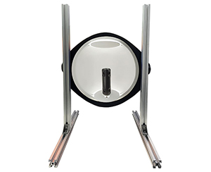
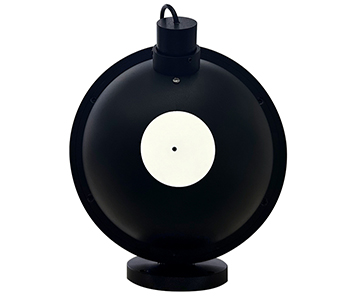
- **Sample Placement**:
Mount the sample flush against the integrating sphere entrance, ensuring perpendicular incidence of light and eliminating stray light leakage to guarantee measurement reliability.
- **Reading Acquisition**:
The instrument collects all transmitted light—including both direct and scattered components—via the integrating sphere and directly displays the total transmittance value.
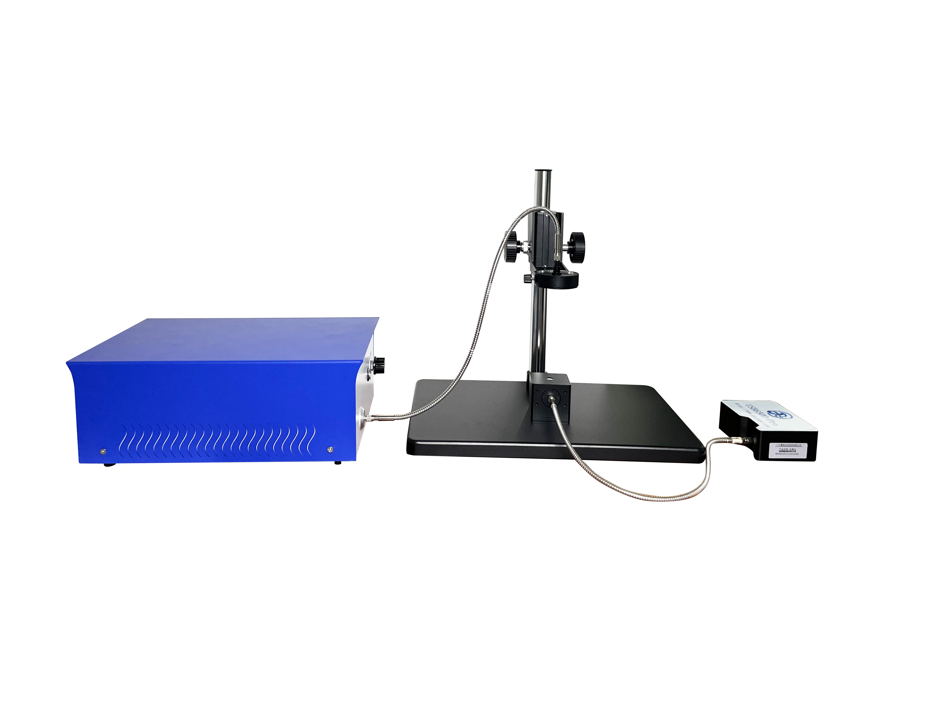
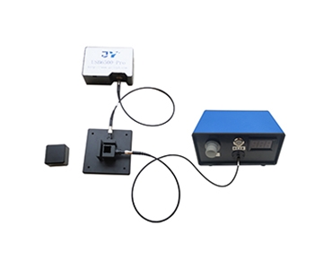
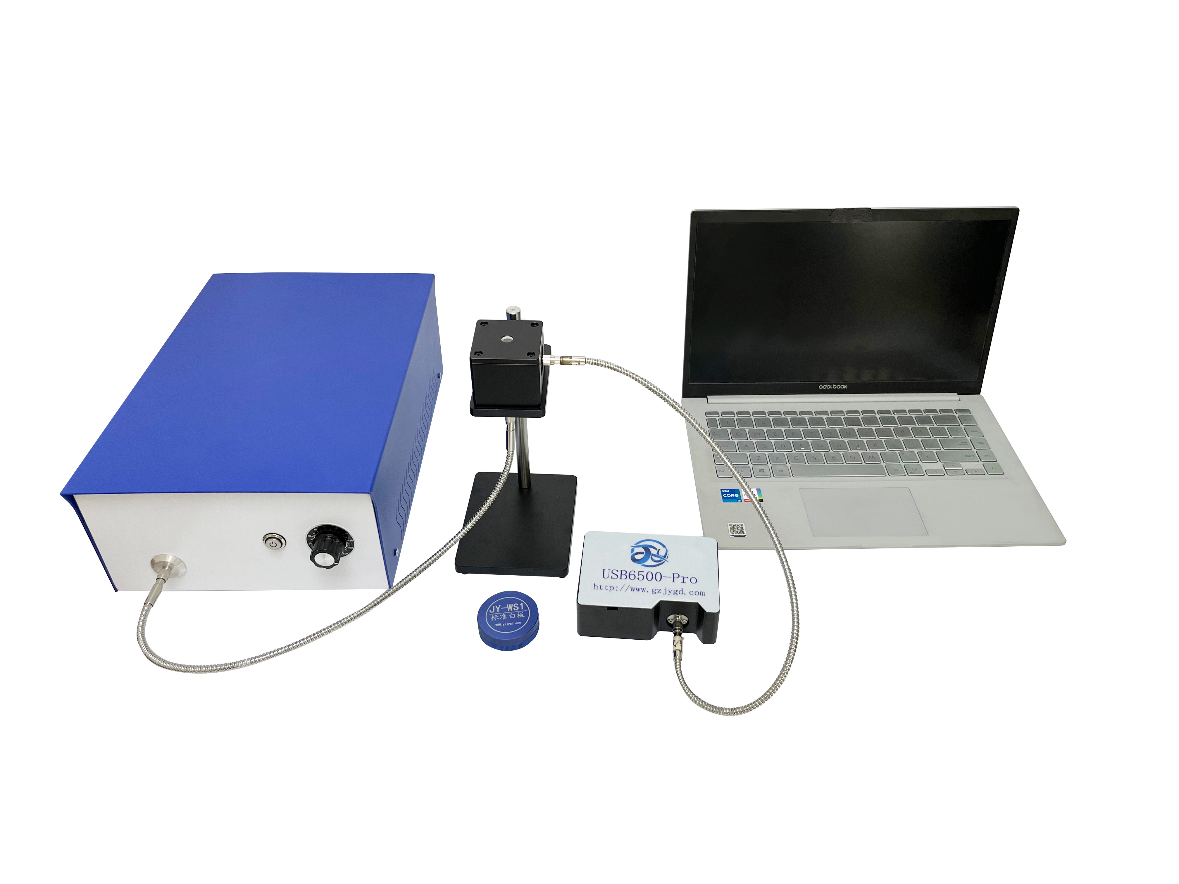
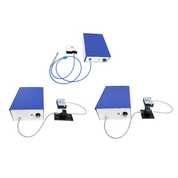
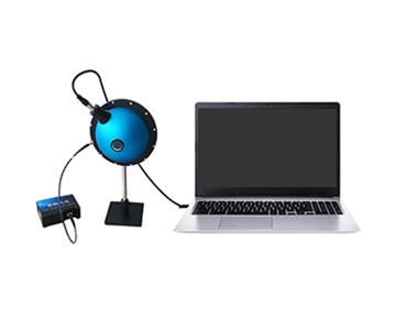
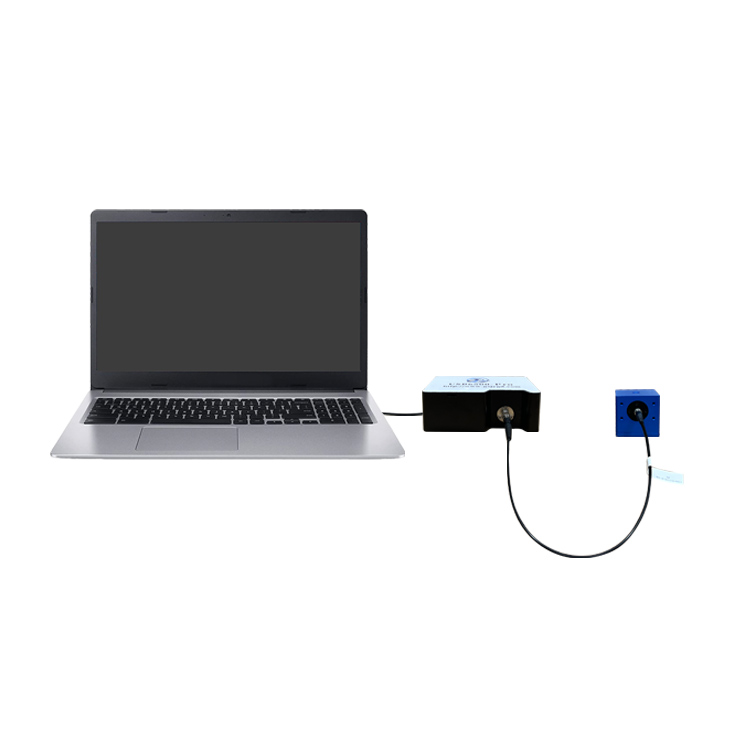
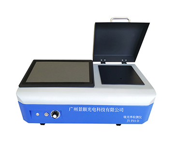
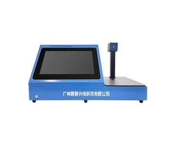
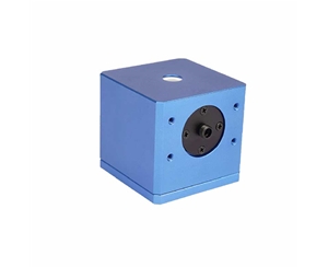
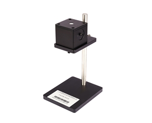
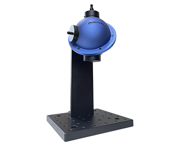
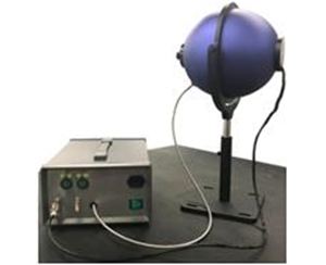
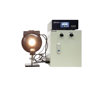
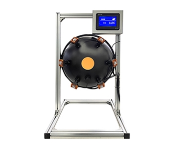
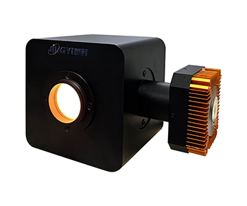
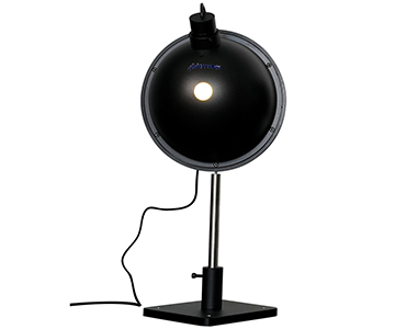
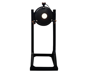
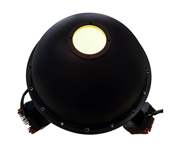
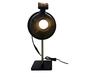
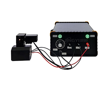
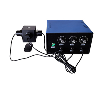
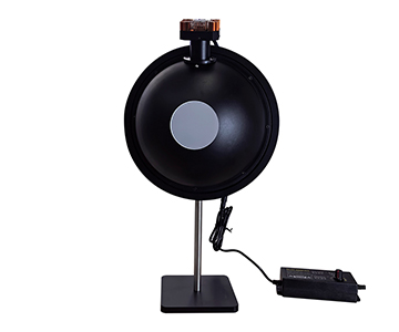
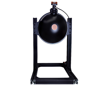
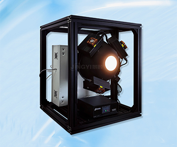
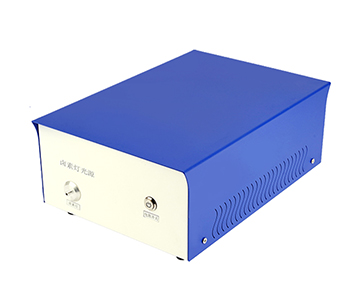
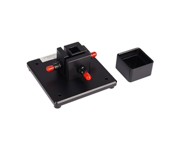
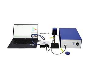
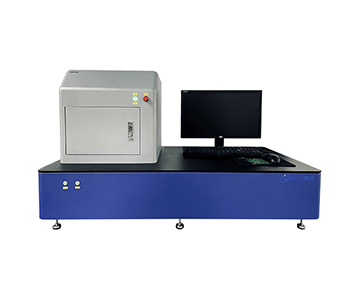
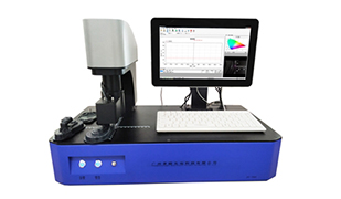
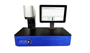
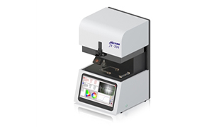
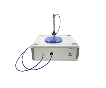
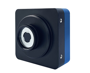
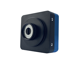
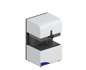
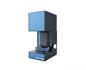
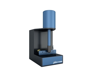
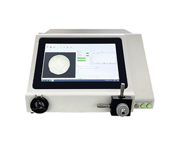
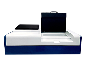
**Technical Advantages of Jingyi Optoelectronics’ JY-T03 Transmittance Meter**
Among numerous transmittance measurement instruments, Jingyi Optoelectronics’ JY-T03 transmittance meter stands out due to its advanced technology and superior performance. Employing spectral measurement technology, it enables full-spectrum transmittance analysis over an exceptionally broad spectral range—from ultraviolet through visible to near-infrared (360–1000 nm)—achieved via optimized optical path design. Its high-intensity light source enables faster, more sensitive detection. Key features include:
- **Real-time Multidimensional Data Display**:
Instantly displays transmittance data across the entire 360–1000 nm range, along with corresponding spectral curves, delivering intuitive, comprehensive measurement results.
- **Customizable Measurement Protocols**:
Users can define customized measurement protocols—including average transmittance calculation and calibration standards—to meet diverse material and application requirements.
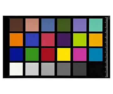
- **Advanced Data Analysis Capabilities**:
Computes CIE colorimetric parameters—including chromaticity coordinates (x, y), CIELAB values (L*, a*, b*), dominant wavelength, saturation, and color purity—enriching optical performance evaluation.
- **Dedicated Testing Software**:
Bundled software supports flexible configuration, storage, and printing of test reports. Embedded management software provides functionalities including customizable measurement setup, spectral data processing, quality inspection, CIE color measurement, open-access database integration, and report generation—offering users a convenient, end-to-end testing and management solution.
- **Compliance with Extensive Domestic and International Standards**:
Fully compliant with numerous global and national standards—including EN, ANSI, AS/NZS, BS EN ISO 12312-1:2013 + A1:2015, ANSI Z80.3–2015, AS/NZS 1067.1:2016, CSA Z94.3–07(R2014), QB 2457–99, QB/T 2506–2017, GB/T 11417.5–2012, EN 166:2001–EN 170:2002, EN 166:2001–EN 172:1994, ANSI Z87.1–2015, and ASTM F659–10—ensuring accuracy, traceability, and reliability of measurement outcomes. Widely applied in transmittance and spectral transmittance analysis of optical components, thin films, filters, flat glass, eyeglass lenses, photovoltaic glass, display panels, smartphone screens, and touch panels.
**Critical Factors Influencing Transmittance Measurement Results**
*Sample Condition*
- **Thickness**:
Material thickness significantly impacts transmittance: generally, transmittance decreases with increasing thickness. Therefore, consistent thickness across samples is strictly required to ensure comparability of results.
- **Surface Condition**:
Surface imperfections—including scratches, contaminants, or roughness—enhance light scattering and reduce transmittance. Prior to testing, samples must be thoroughly cleaned and surface-treated to achieve smoothness and planarity.
*Light Source Wavelength*:
Different materials absorb and transmit light differently across wavelengths. For example, UV radiation is readily absorbed by many plastics, while certain materials exhibit relatively high transmittance in the infrared region. Hence, wavelength selection—visible, UV, or IR—must align with both material properties and intended application.
*Instrument Precision*:
Factors such as spectrophotometer wavelength accuracy and integrating sphere size directly affect measurement fidelity. Regular instrument calibration and preventive maintenance are thus essential to sustain optimal operational performance.
*Environmental Conditions*:
Ambient lighting conditions influence transmittance readings. To minimize stray-light interference, measurements should be conducted in a darkroom or under controlled, stray-light-free conditions.
**Key Considerations for Transmittance Testing**
*Distinction Between Haze and Transmittance*:
While transmittance quantifies a material’s overall light transmission capability, haze characterizes the degree of transmitted-light scattering—i.e., optical turbidity. In practice, both parameters are often measured concurrently; GB/T 2410, for example, details standardized procedures for simultaneous transmittance and haze measurement of transparent plastics.
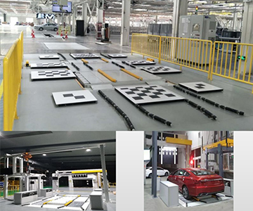
*Testing Specialized Materials*:
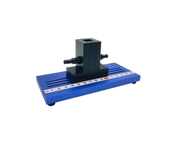
- **Non-planar or Curved Surfaces**:
For irregular or curved substrates—e.g., automotive windshields—dedicated fixtures must secure the sample to mitigate refractive errors and preserve measurement integrity.
- **Liquid Samples**:
When measuring liquids, solvent evaporation and bubble formation may compromise accuracy. Best practice recommends preparing and measuring samples immediately, while minimizing agitation and bubble generation during testing.
*Personal Safety Precautions*:
UV radiation poses risks to ocular health. During UV measurements, operators must wear certified UV-protective eyewear and avoid direct exposure to the light source to ensure personal safety.
By comprehensively understanding transmittance measurement principles, methodologies, influencing factors, and procedural cautions—and leveraging advanced instrumentation such as Jingyi Optoelectronics’ JY-T03 transmittance meter—researchers and engineers can obtain highly accurate transmittance data, thereby providing robust technical support for optical material development, manufacturing, and application. Furthermore, continuous technological innovation and advancement will further refine transmittance measurement techniques, fueling new momentum for progress across the broader field of optical materials.
#TransmittanceMeter #TransmittanceAnalyzer #TransmittanceTestingInstrument #TransmittanceMeasuringInstrument #TransmittanceSpectrometer