In the fields of optical communication and related areas, optical power and integrating sphere optical power meters are essential concepts and measurement tools. Next, we will delve deeply into their specialized knowledge.
**The Nature and Units of Optical Power**
Optical power—termed “luminous power” in English—is a physical quantity measuring the work done by light per unit time. In practical applications, optical power is commonly expressed in milliwatts (mW) and decibel-milliwatts (dBm). Their conversion relationship is defined as: 1 mW = 0 dBm; when optical power is less than 1 mW, its corresponding dBm value is negative. As a fundamental and widely used parameter in optical signal measurement, optical power plays a critical role in evaluating the performance of optical communication systems, as well as in the research, development, and manufacturing of optical components.
**Functions, Types, and Applications of Integrating Sphere Optical Power Meters**
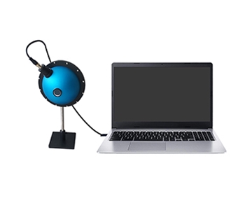
An integrating sphere optical power meter—commonly referred to in English as an “optical power meter”—is primarily used to measure absolute optical power or the relative optical power loss across a fiber segment. Within fiber-optic systems, measuring optical power is analogous to using a multimeter to measure basic electrical parameters in electronics: it is a foundational and indispensable measurement step. Integrating sphere optical power meters are widely deployed across fiber-optic measurement applications and constitute standard instrumentation.
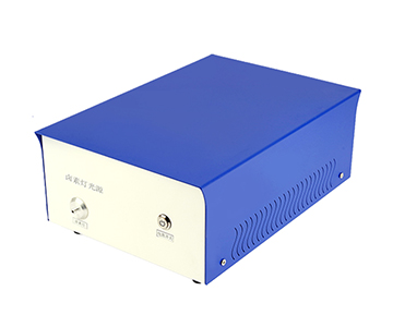
By measuring the absolute power output from transmitters or optical networks using an integrating sphere optical power meter, engineers can effectively evaluate the performance of optical terminal equipment. When paired with a stabilized light source, the integrating sphere optical power meter’s capabilities expand significantly: it not only measures connection loss but also verifies fiber link continuity and supports assessment of overall transmission quality.
Throughout the entire lifecycle of fiber-optic transmission systems—including manufacturing, installation, operation, and maintenance—optical power measurement remains a critical step. Indeed, in the fiber-optic domain, without an integrating sphere optical power meter, virtually no engineering site, laboratory, production workshop, or telecommunications maintenance facility could function normally. For instance, such meters are used to measure the output power of laser and LED sources, enabling engineers to characterize source performance; they help verify estimated fiber-link losses, providing vital data for fiber-network design and optimization; most importantly, they serve as key instruments for testing performance metrics of various optical components—including optical fibers, connectors, splices, and attenuators.
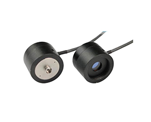
Integrating sphere optical power meters are categorized primarily into two types based on the active area size of their built-in photodetectors:
- *Large-area photodetector integrating sphere optical power meters*, whose photodetectors typically have a diameter of ~5 mm—ideal for measuring collimated beams and yielding accurate power readings for such beams;
- *Small-area photodetector integrating sphere optical power meters*, whose photodetectors have diameters under 1 mm—offering higher sensitivity and lower cost, yet presenting greater challenges in calibration.
**Key Selection Criteria for Integrating Sphere Optical Power Meters**
When selecting a suitable integrating sphere optical power meter, four critical factors must be comprehensively considered:
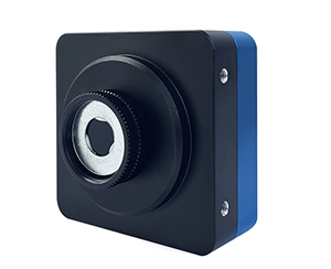
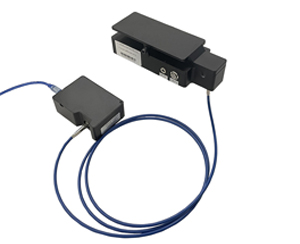
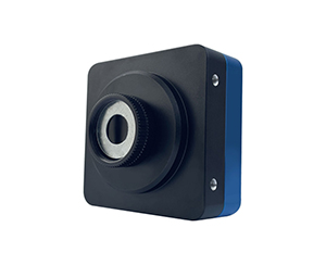
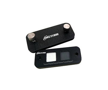
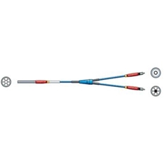
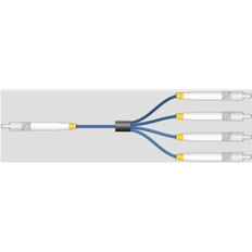
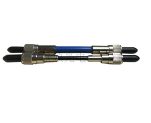
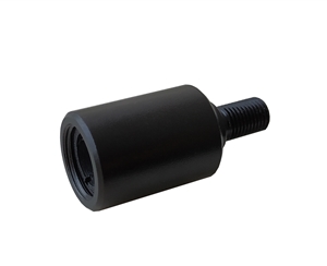
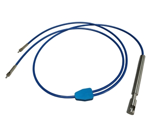
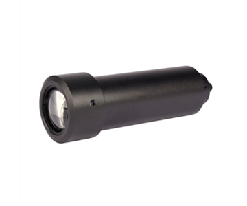
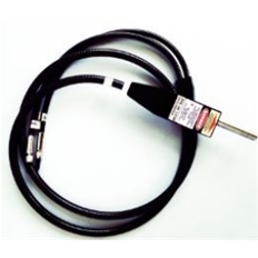
1. **Probe Type and Connector Interface Compatibility**: First, choose an appropriate probe type and compatible connector interface. Common connector types include LC, MPO/MTP, SC, ST, FC, and MT-RJ. The optical probe—an integral solid-state photodiode component—receives coupled light from the fiber network and converts it into an electrical signal. Light signals may be delivered to the probe via dedicated connector interfaces or through a Universal Connector Interface (UCI) adapter (threaded coupling), which accommodates most industrial-standard connectors. Based on calibration factors specific to the target wavelength, the meter’s circuitry converts the probe’s output signal and displays the resulting optical power reading in dBm units. Therefore, one key selection criterion is matching the probe type to the intended operational wavelength range. Notably, InGaAs detectors perform well across all three telecom windows (850 nm, 1300 nm, and 1550 nm); compared to Ge detectors, InGaAs exhibits flatter spectral response across these bands, delivers superior measurement accuracy at 1550 nm, and offers better temperature stability and lower noise.
2. **Calibration Accuracy and Manufacturing Calibration Procedures**: Thoroughly assess the meter’s calibration accuracy and underlying manufacturing calibration procedures to ensure alignment with fiber and connector specifications. In practice, variations among different adapter types can introduce measurement uncertainty; thus, analyzing root causes and accounting for other potential error sources is essential. Although NIST (National Institute of Standards and Technology) establishes U.S. national standards, differences in spectral characteristics among seemingly identical light sources, photodetectors, and connectors produced by various manufacturers further complicate and increase uncertainty in measurements.
3. **Measurement Range and Display Resolution**: Selecting a model with an appropriate measurement range is equally important. Expressed in dBm, the instrument’s dynamic range—a comprehensive specification—must encompass both the minimum and maximum input signal levels required, ensuring accuracy, linearity (typically ±0.8 dB), and resolution (commonly 0.1 dB or 0.01 dB) meet application requirements across all operating conditions. Matching the probe type to the expected operational range remains a core selection criterion to guarantee measurement accuracy and reliability.
4. **dB Functionality (Relative Power Measurement)**: The meter must support dB functionality (i.e., relative power measurement), which provides significant practical utility. Direct readout of optical loss dramatically improves measurement efficiency and accuracy. Without this feature, technicians must manually record reference and measured values separately and then perform cumbersome calculations to derive loss—increasing workload and introducing risk of human computational errors. In contrast, meters with dB capability deliver relative loss results directly, thereby enhancing productivity and minimizing calculation-related errors.
**Fundamental Specifications of Integrating Sphere Optical Power Meters**
The core technical specifications of integrating sphere optical power meters fall into the following four categories:
- **Wavelength Range**: This specification closely correlates with the type of photodetector employed internally. For example, silicon (Si) detectors typically cover 450–1000 nm, while gallium arsenide (GaAs) detectors operate over ~800–1700 nm. Since different detector types suit distinct wavelength bands, users must select a meter with a detector matched to the target measurement wavelengths to ensure accurate power measurements across the desired spectrum.
- **Maximum and Minimum Detectable Power Range**: The measurable power range constitutes a critical performance metric. A typical range is −100 to +3 dBm, indicating high accuracy and reliability within this span. In practice, users must select a meter whose power range aligns with the magnitude of the optical signal under test—avoiding inaccurate results or potential damage to the instrument.
- **Display Resolution**: Display resolution is generally specified in dB or watts (W). Typical values are 0.001 dB or 10 pW. Higher resolution yields more precise measurements, facilitating finer analysis and evaluation of optical signal performance.
- **Internal Noise**: The internal noise generated by the power meter is another crucial specification. Typical internal noise levels range from 1 to 50 pW. Lower internal noise enhances measurement sensitivity and accuracy—especially critical when measuring weak optical signals, where noise effects become markedly pronounced.
**Differentiation Among Optical Power–Related Concepts**
Several related concepts are often confused within the context of optical power: illuminance, luminous intensity, luminous flux, radiant energy, and optical power. Below, we clarify each:
- **Illuminance**: Also termed illumination or simply “illuminance”, this quantifies the degree to which a surface is illuminated—i.e., the incident light flux per unit area on a given surface. Its SI unit is the lux (lx), equivalent to 1 lumen per square meter (1 lx = 1 lm/m²). Illuminance describes how much light strikes a surface and depends on incidence angle, source strength, and surface reflectivity.
- **Luminous Intensity**: Commonly abbreviated as “luminous intensity” or “intensity”, this is a photometric quantity describing the luminous power emitted by a source in a particular direction per unit solid angle. Its SI unit is the candela (cd). Luminous intensity is a vector quantity—characterized by both magnitude and direction—and reflects the directional brightness of a light source.
- **Luminous Flux**: Defined as the total amount of visible light emitted, transmitted, or received per unit time, luminous flux is measured in lumens (lm). Though sometimes mistakenly equated with radiometric power (watts), it represents photometrically weighted radiant power—the perceived power adjusted for human eye sensitivity. It is a scalar quantity, independent of propagation direction.
- **Radiant Energy and Optical Power**: Radiant energy refers to the total energy carried by electromagnetic radiation; optical power (radiant power) is the rate at which that energy is transferred—i.e., radiant energy per unit time—measured in watts (W) or submultiples (e.g., mW). While “optical power” and “radiant power” are technically synonymous in radiometry, in photometry “luminous power” denotes photometrically weighted power (in lumens). In common usage—especially in optical communications—“optical power” usually implies radiant power, and units like mW and dBm are standard. These two concepts are intrinsically linked: radiant energy equals optical power integrated over time. Practically, optical power is routinely measured to infer radiant energy characteristics.
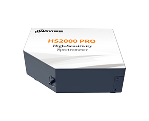
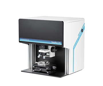
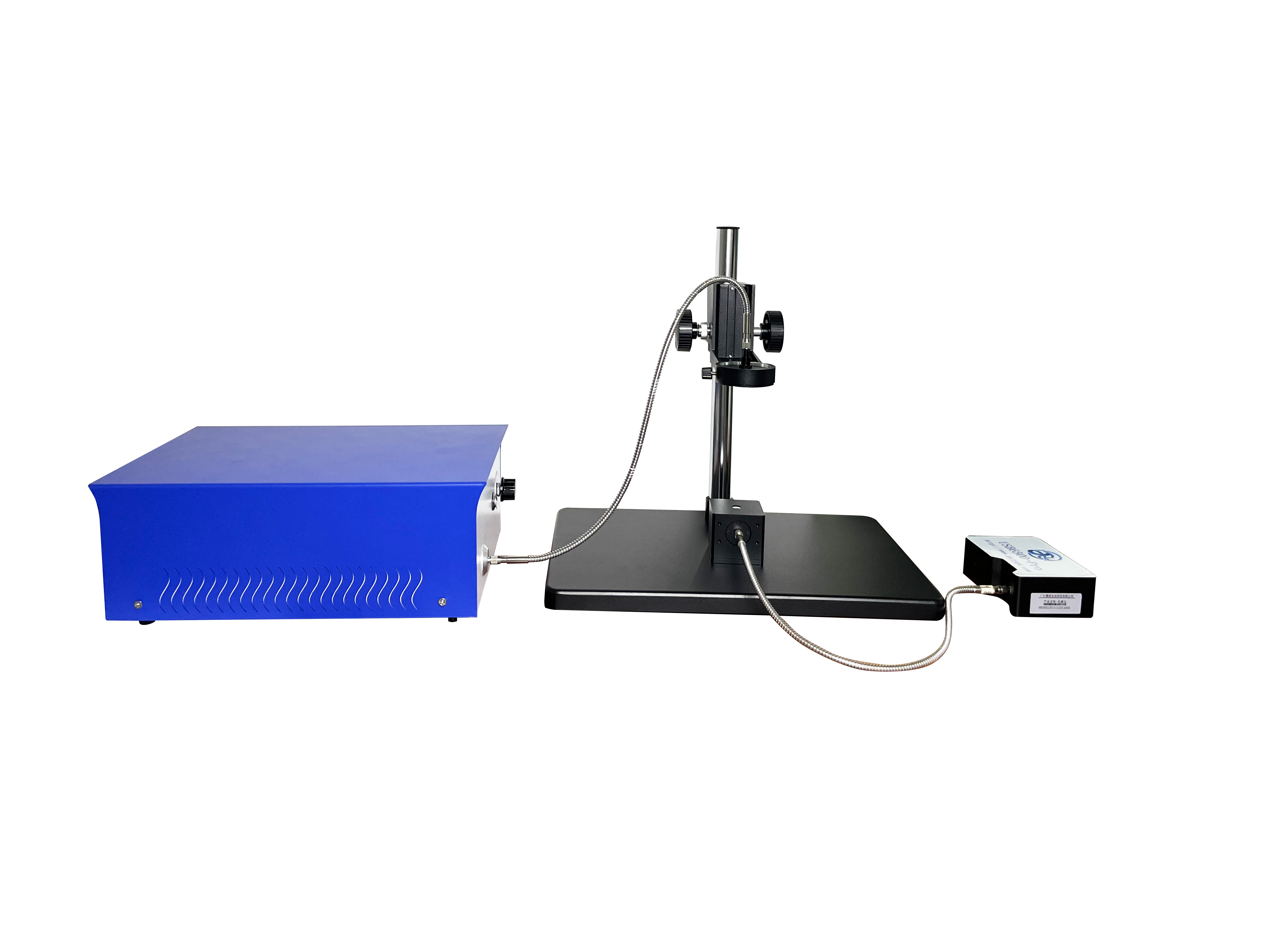
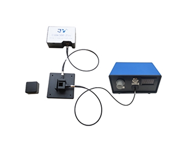
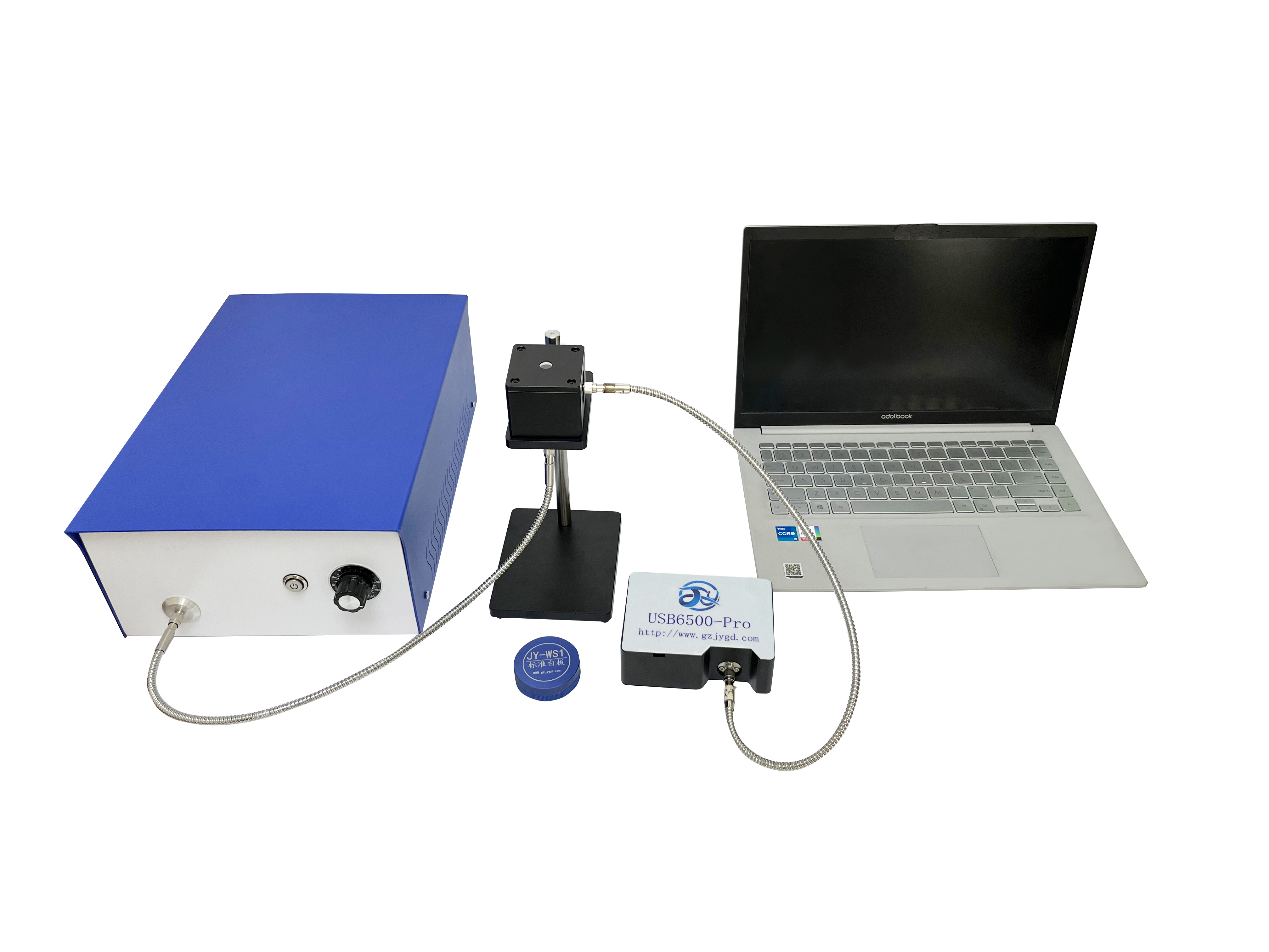
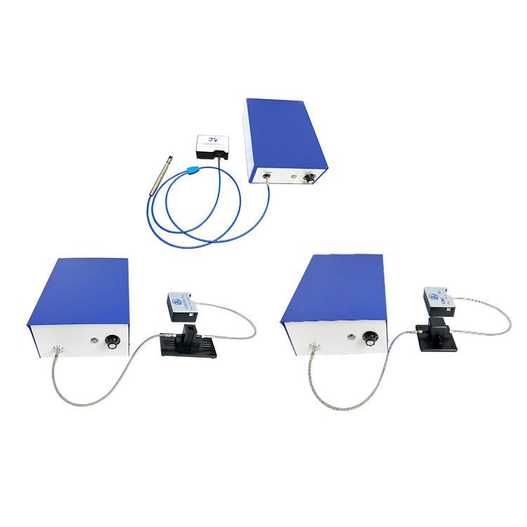
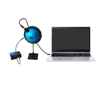
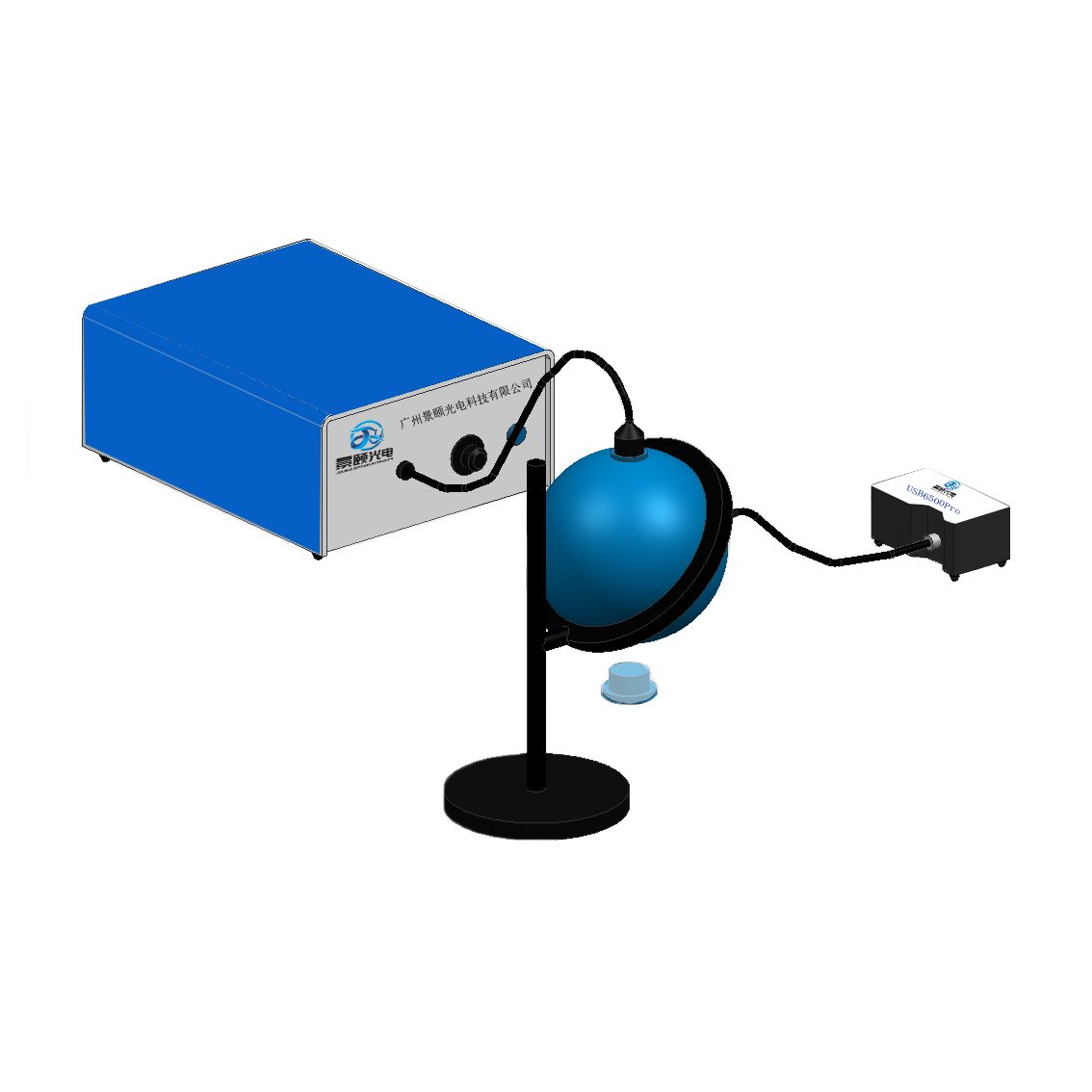
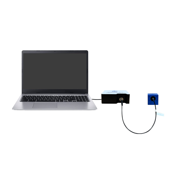
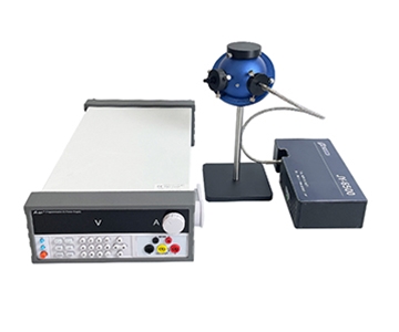
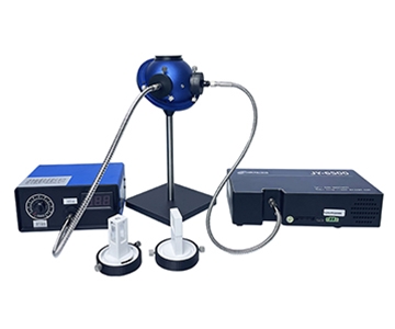
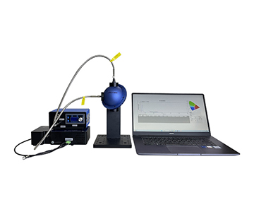
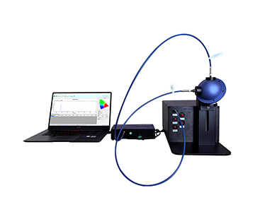
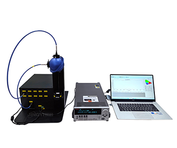
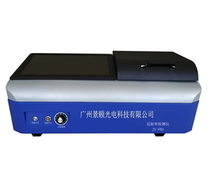
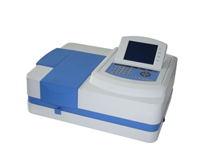
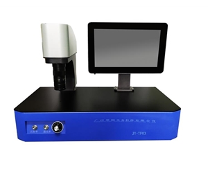
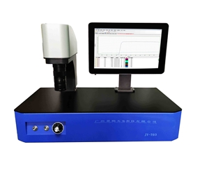
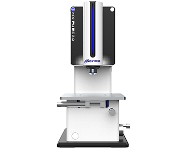
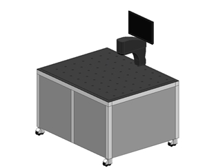
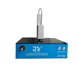
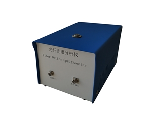
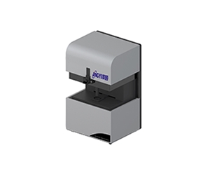
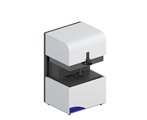
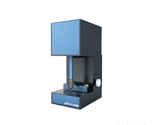
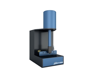
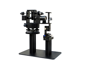
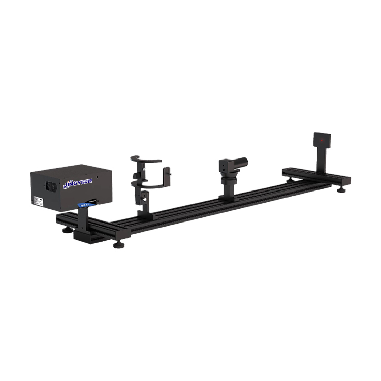
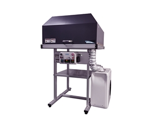
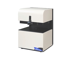
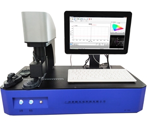
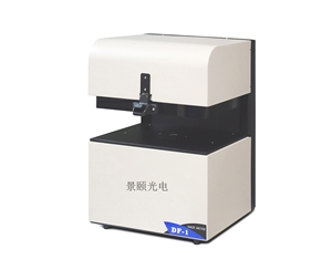
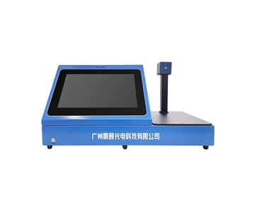
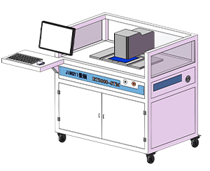
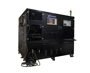
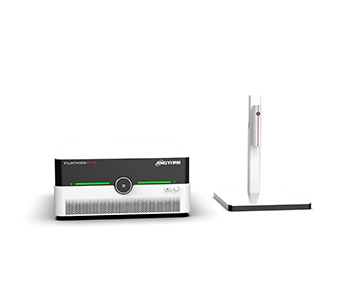
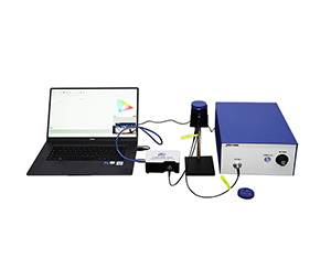
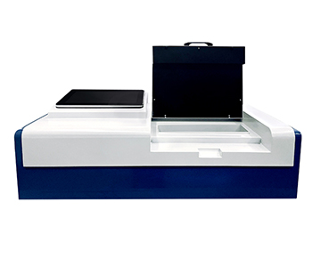
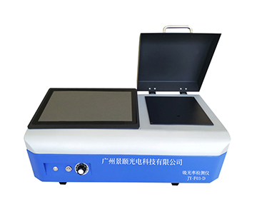
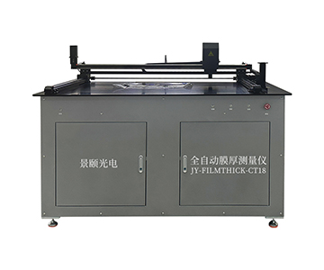
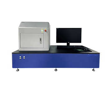
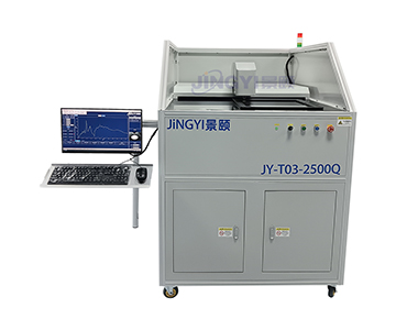
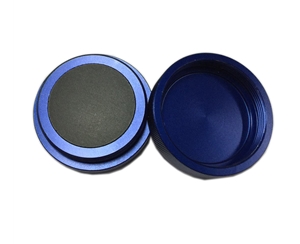
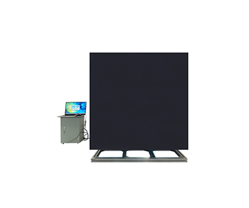
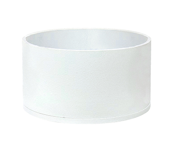
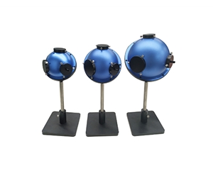
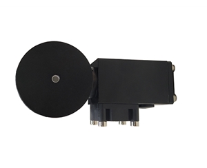
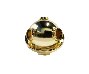
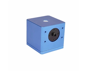
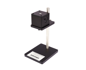
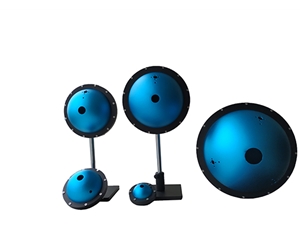
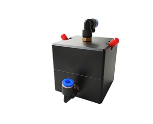
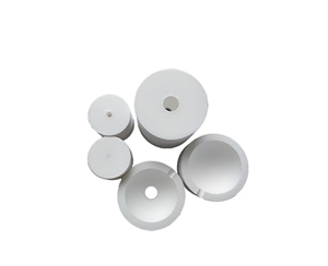
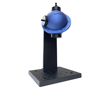
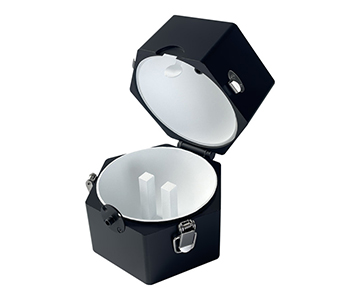
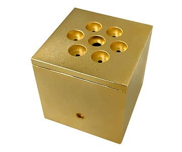
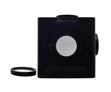
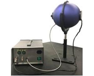
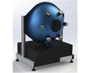
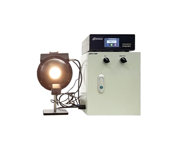
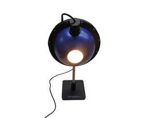
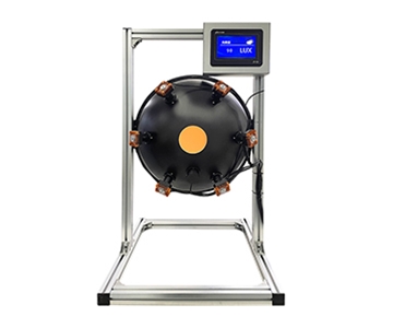
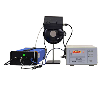
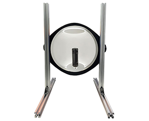
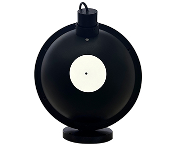
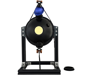
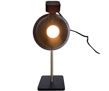
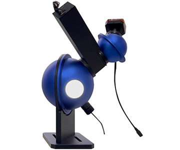
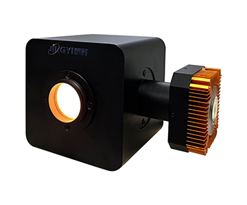
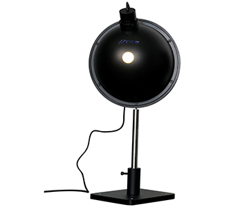
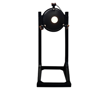
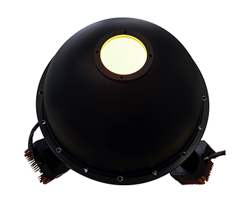
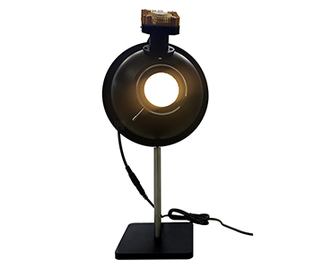
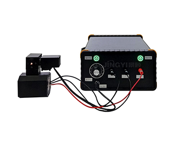
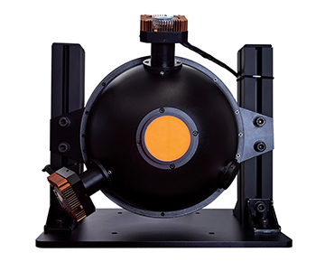
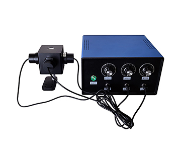
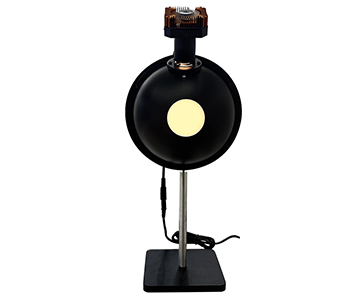
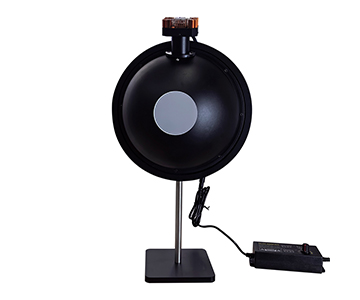
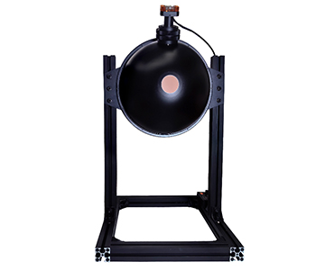
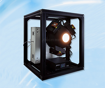
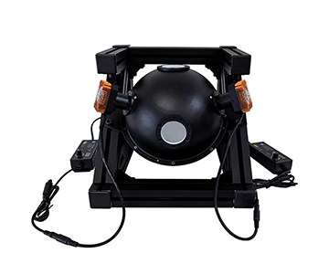
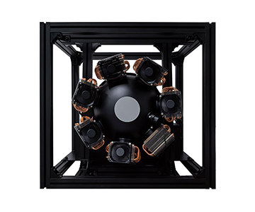
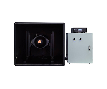
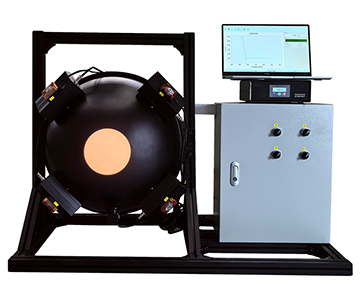
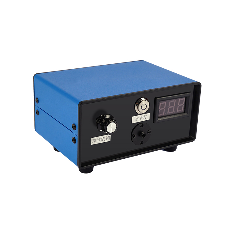
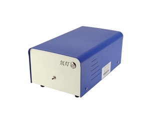
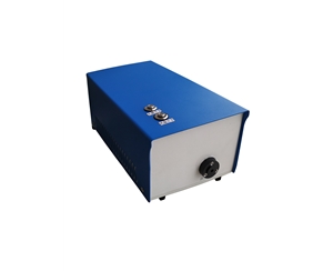
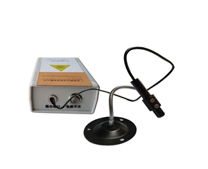
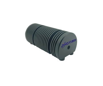
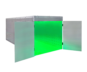
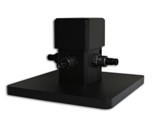
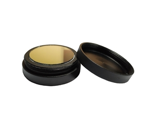
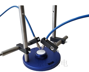
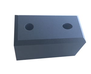
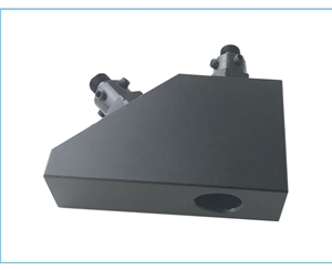
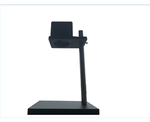
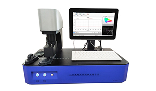
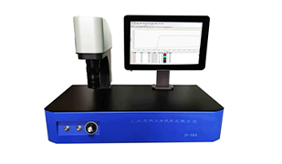
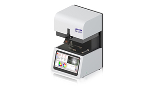
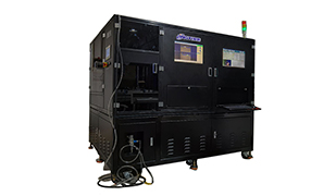
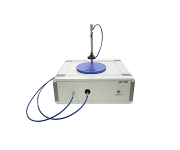
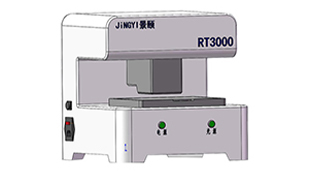
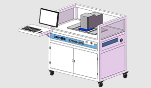
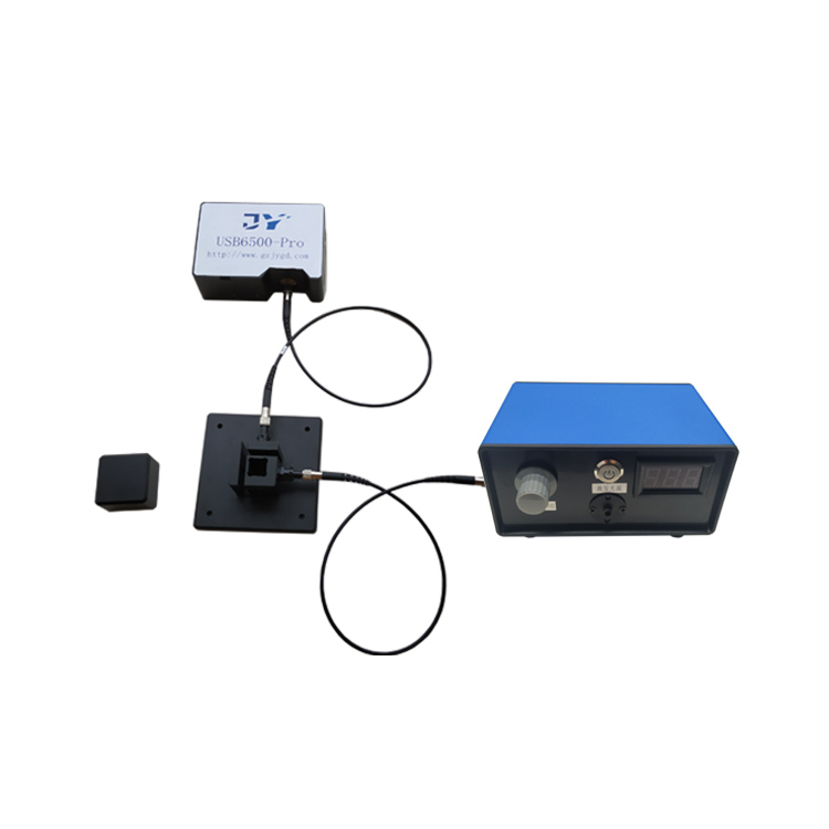
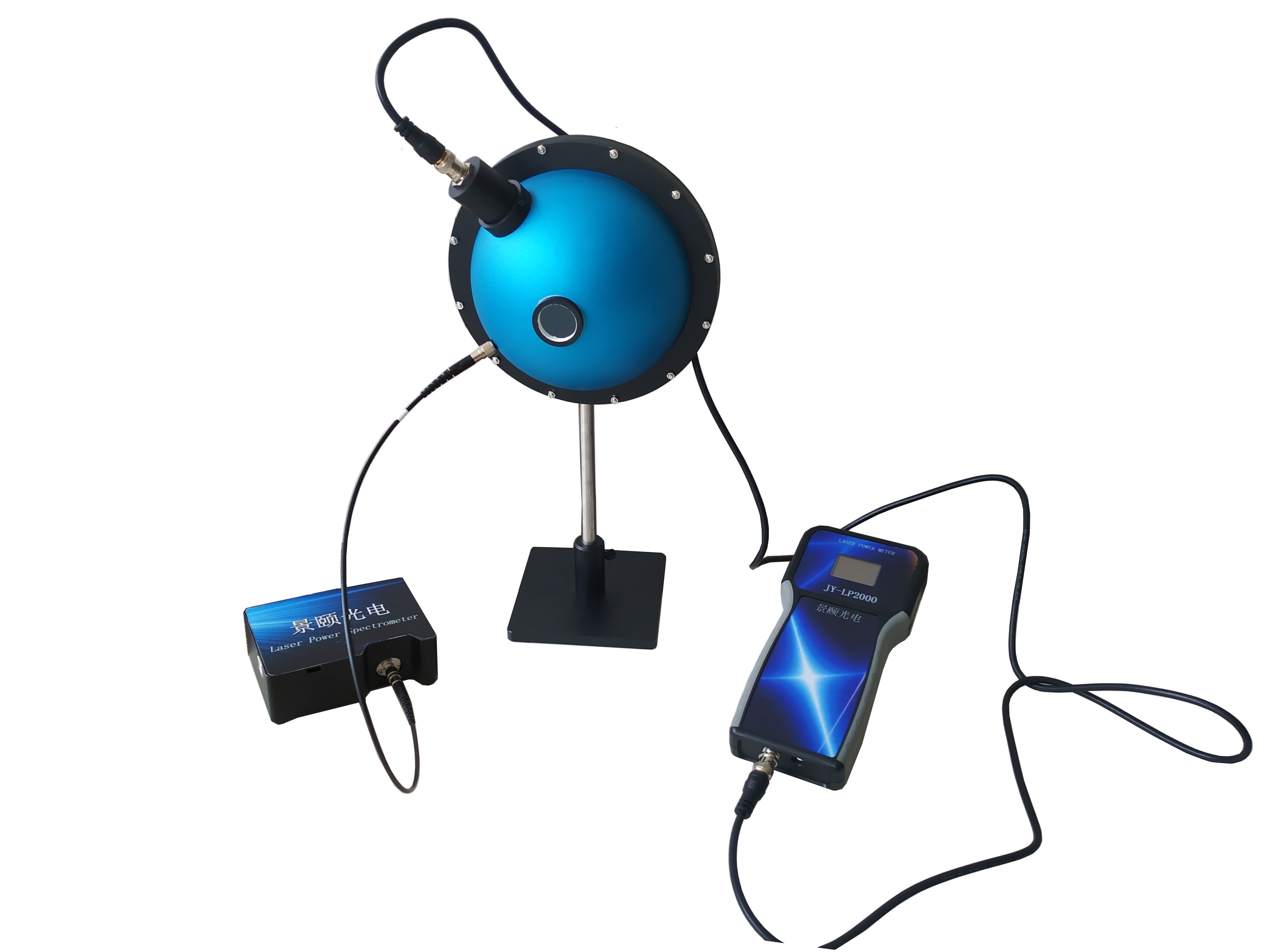
Throughout the evolution of optical communication and related fields, Jingyi Optoelectronics has consistently focused on R&D and innovation in optical power measurement technologies. Jingyi’s integrating sphere spectroradiometric power measurement system offers a robust solution for optical power characterization. Utilizing a PTFE-based high-diffuse-reflectance integrating sphere to collect light, its geometric design ensures laser power measurements remain unaffected by beam polarization or calibration drift—enabling accurate spectral and power characterization of light sources. The system separately measures source power (via the integrating sphere optical power meter) and wavelength (via a fiber-coupled spectrometer), with results displayed and processed through dedicated software. For specialized applications, optional calibrated attenuation modules can be integrated. Furthermore, the system’s calibration is traceable to NIST (National Institute of Standards and Technology), assuring measurement accuracy and reliability. Jingyi’s integrating sphere spectroradiometric power measurement system holds strong application potential across optical component R&D and manufacturing, as well as optical communication system testing—contributing meaningfully to advances in optical communication technology.
#IntegratingSphereLaserPowerMeter #LaserPowerMeter #IntegratingSphereOpticalPowerTester #IntegratingSphereOpticalPowerMeter #PhotodetectorPowerMeter #OpticalPowerTester #OpticalPowerMeter