For R&D engineers working in the RF/microwave domain, the vector network analyzer (VNA) is an indispensable core instrument for device performance verification. Yet most users focus solely on its S-parameter measurement capability and remain largely unaware of the reflectometer unit—the critical subsystem that ultimately determines the upper limit of measurement accuracy—making them highly susceptible to test errors arising from architectural differences.
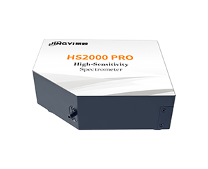
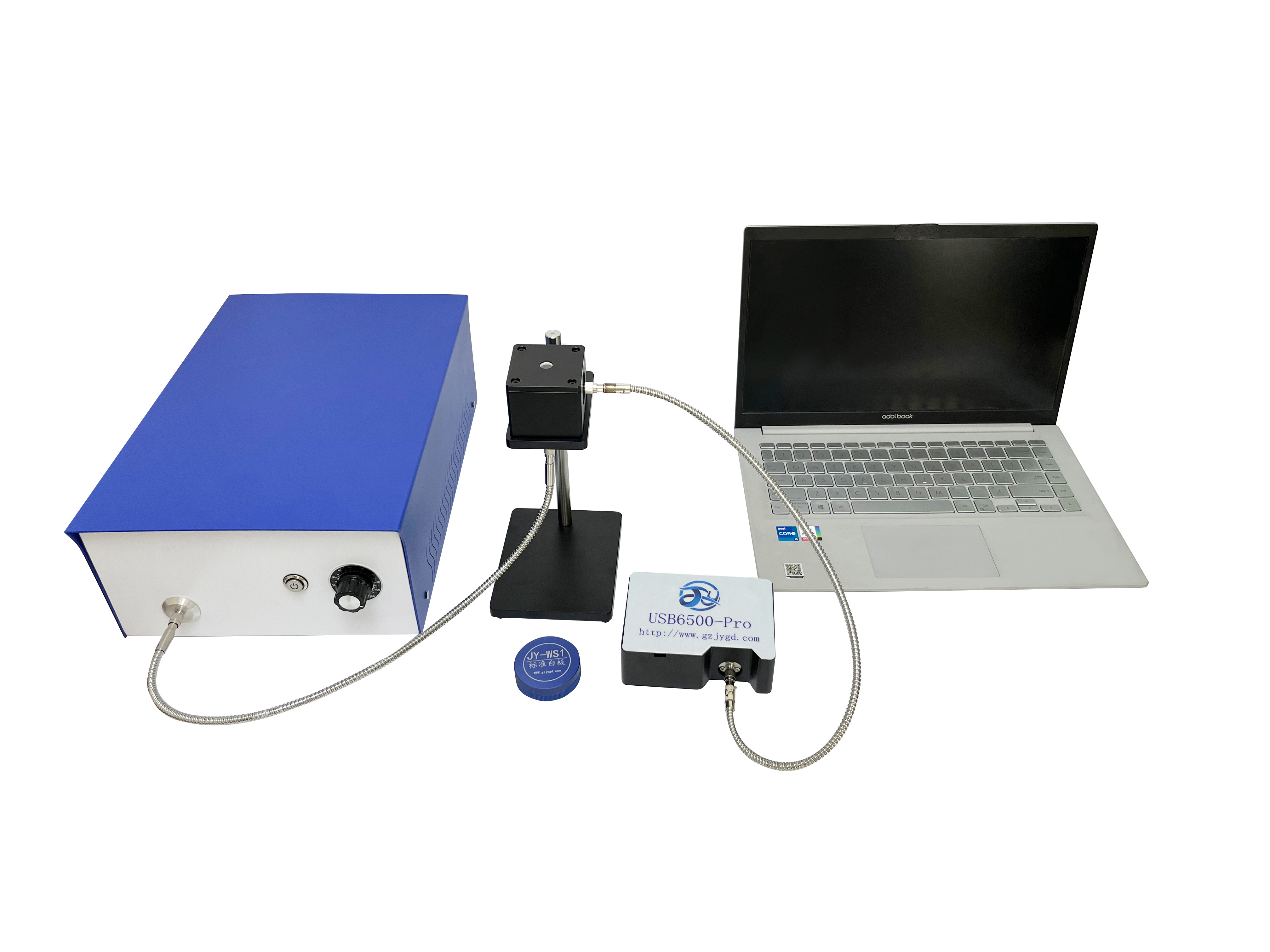
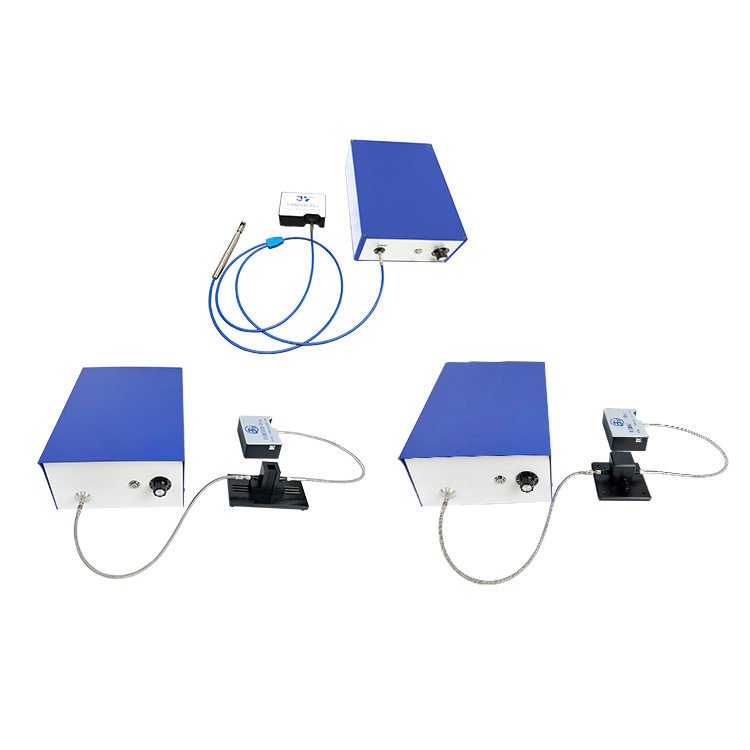
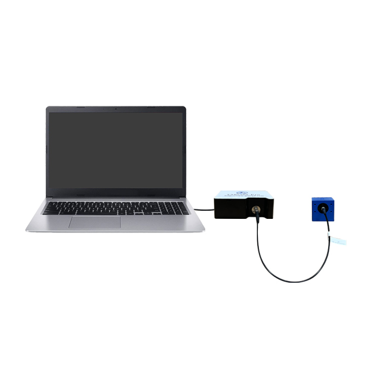
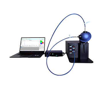
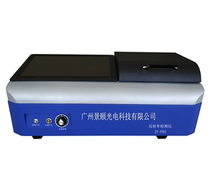
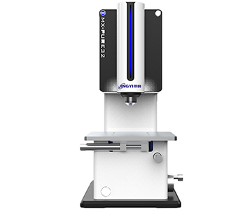
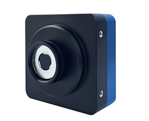
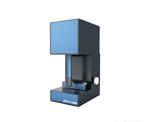
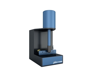
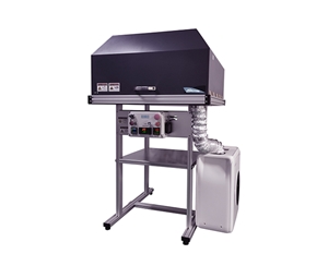
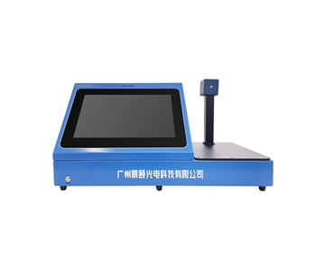
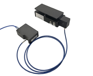
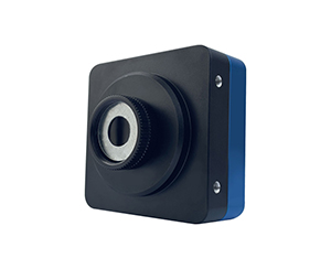
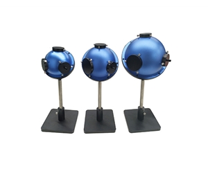
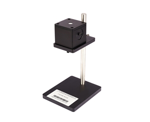
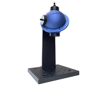
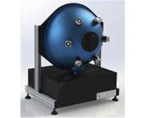
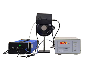
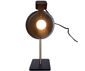
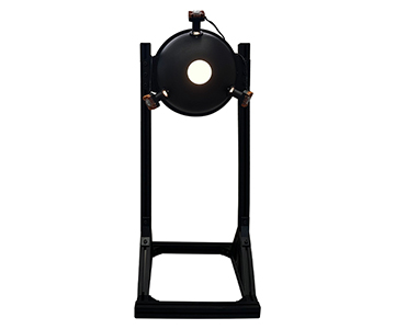
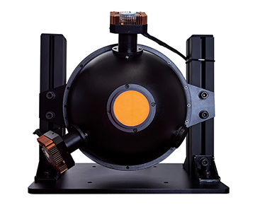
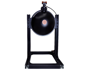
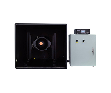
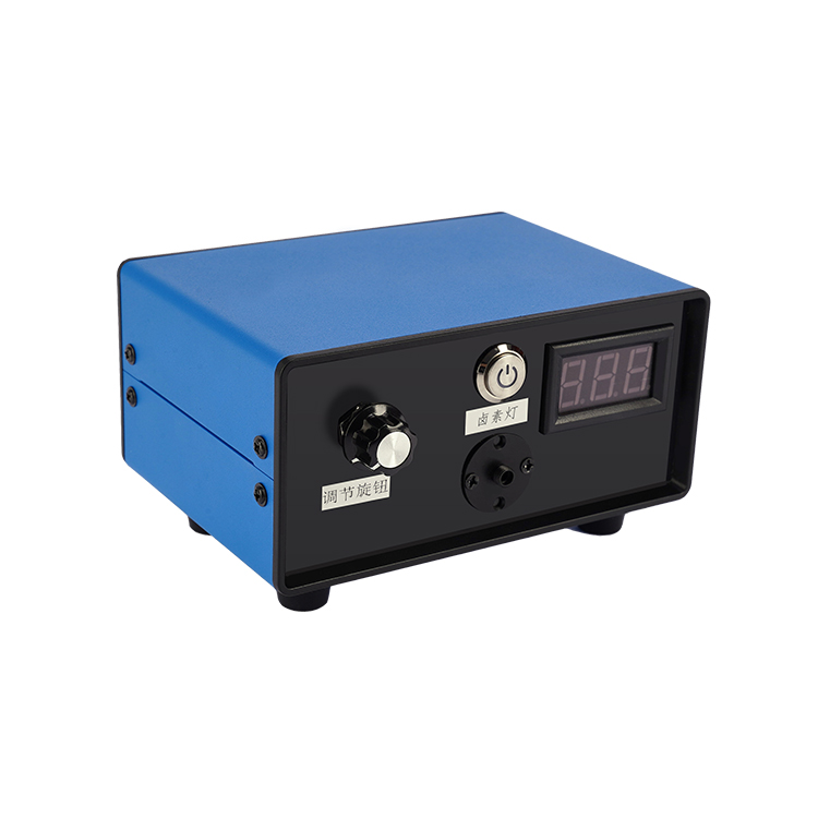
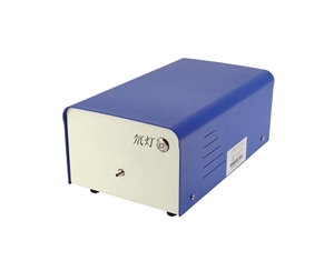
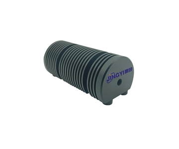
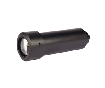
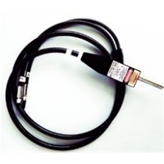
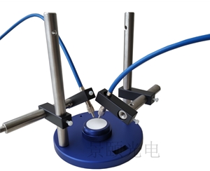
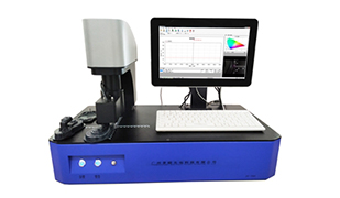
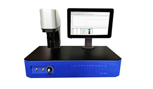
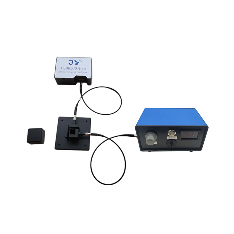
The fundamental principle of a reflectometer is remarkably intuitive: it first delivers a single-frequency or swept-frequency stimulus signal of specified power to the device under test (DUT), then compares both the amplitude and phase of the reflected signal against those of the original incident signal to compute an accurate reflection coefficient. This underlying logic is fundamentally identical to material reflectance measurement in optical science—both rely on ratio-based calculations between incident and reflected signals to cancel out systematic errors. When Jingyi Optoelectronics developed its proprietary JY-F03 series reflectometers, it adopted precisely this calibration philosophy—effectively eliminating numerical drift caused by thermal drift in broadband light sources—and thereby achieving exceptional stability and high precision across the full 380–1000 nm spectral range.
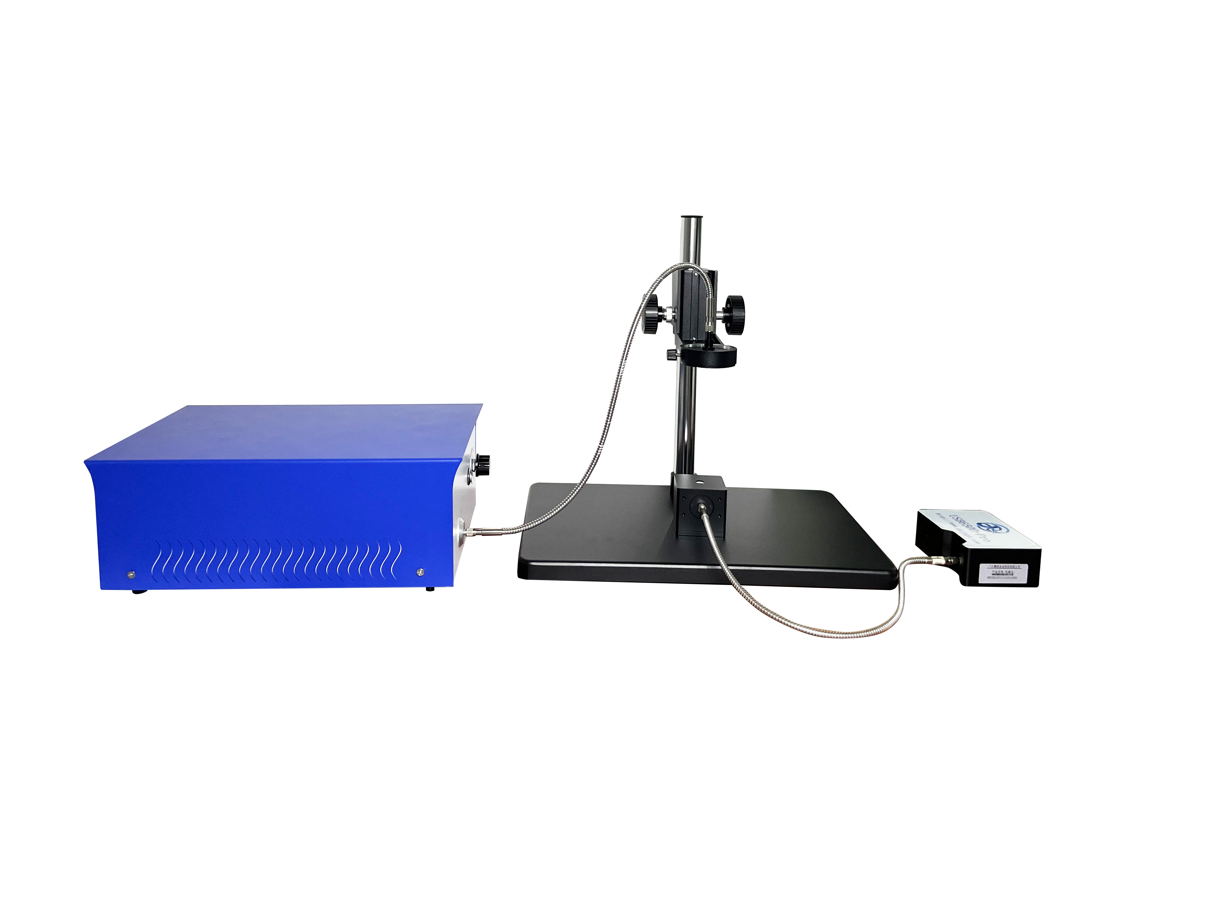
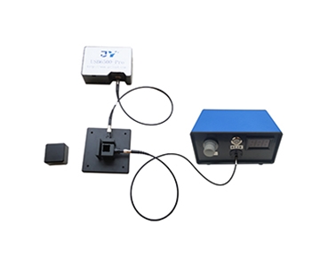
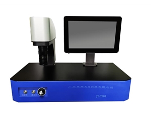
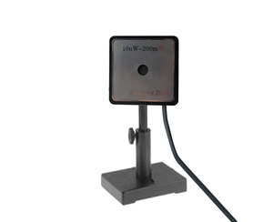
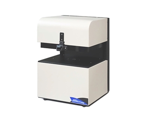
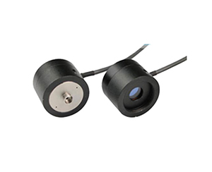
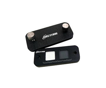
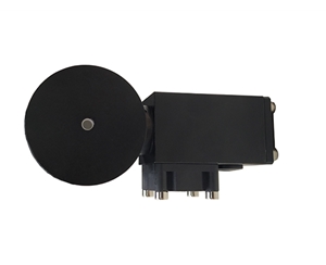
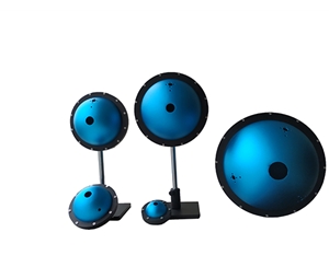
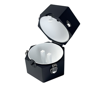
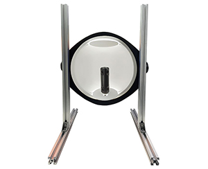
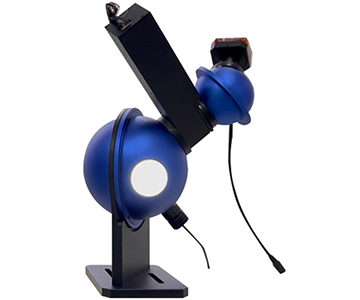
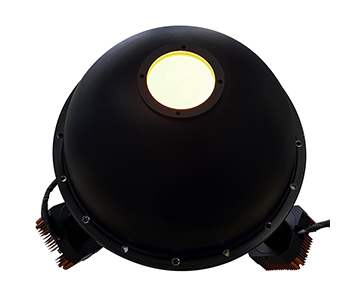
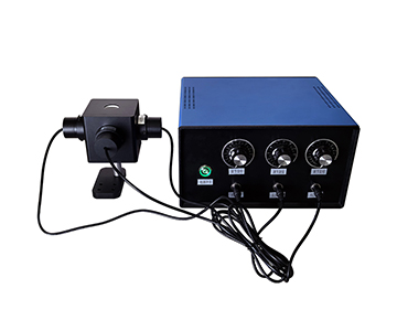
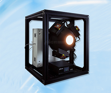
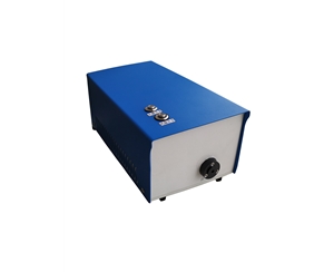
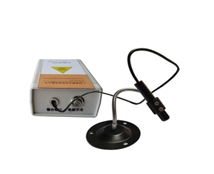
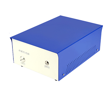
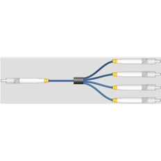
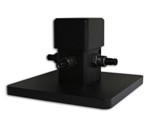
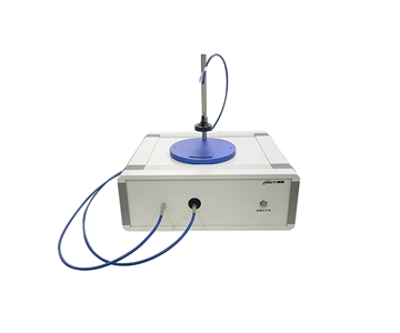
Many engineers new to VNAs raise a common question: “Since the instrument can set output power, isn’t it sufficient to simply compare the measured reflected signal against the preset power value? Why add an extra reference receiver?” The answer lies in two essential reasons: First, the signal source’s actual output power exhibits minor fluctuations and therefore cannot serve as a reliable computational reference. Second, the preset power value contains only amplitude information—not phase data—yet S-parameters are vector quantities requiring both amplitude *and* phase for accurate computation. Hence, a dedicated reference receiver is indispensable: it continuously captures both amplitude and phase of the incident signal to provide a real-time calibration baseline. This design mirrors Jingyi’s JY-F03 dual-optical-path architecture: one path monitors incident light intensity at the sample surface; the other captures the reflected light. Even if LED light sources gradually dim over time or ambient temperature shifts cause wavelength drift, error cancellation via ratio computation between the two paths ensures measurement accuracy—eliminating the need for frequent recalibration.
The directional component inside the reflectometer—responsible for separating incident and reflected signals—is the key determinant of signal isolation performance. VNAs operating below 10 GHz typically employ VSWR bridges as directional elements, whereas higher-frequency instruments almost universally adopt dual-directional couplers to ensure superior signal isolation and prevent measurement errors caused by crosstalk between incident and reflected signals. Some VNAs integrate Bias-Tee modules into their reflectometers to conveniently supply DC bias to active DUTs—without requiring external power circuitry. Additionally, two types of step attenuators are commonly included: one placed at the stimulus source output to extend the adjustable port power range; the other positioned at the front end of the measurement receiver to prevent saturation and distortion when large signals are input. Such attenuators are primarily used during testing of high-power devices—for example, power amplifiers.
Beyond directional components, the physical placement of the source step attenuator also represents a prominent architectural distinction among VNA brands. Two mainstream design approaches exist today: (1) placing the attenuator between the stimulus source and the directional element; and (2) positioning it between two independent directional couplers. These differences are nearly imperceptible when measuring passive devices—but become markedly evident during testing of high-gain active components such as power amplifiers. Architecture (1) offers the advantage that, after performing a full-port calibration at high power, subsequent reductions in output power via attenuator adjustment do *not* require recalibration. Its drawback, however, is that the attenuator simultaneously reduces signal strength entering the reference receiver—leading to lower SNR and greater trace fluctuation in low-power measurements. Manufacturers typically mitigate noise by narrowing the sampling bandwidth and applying multi-sample averaging algorithms—though this inevitably sacrifices some measurement speed. In contrast, architecture (2) preserves the reference receiver signal path free of attenuation, yielding higher SNR and smoother traces at low power. Its trade-off is that any change in attenuator setting invalidates prior calibration—requiring immediate recalibration at the new power level—which may degrade low-power calibration accuracy. To address this, manufacturers often pre-characterize frequency-response errors associated with each attenuator setting and automatically apply compensation during measurement.
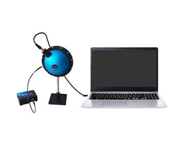
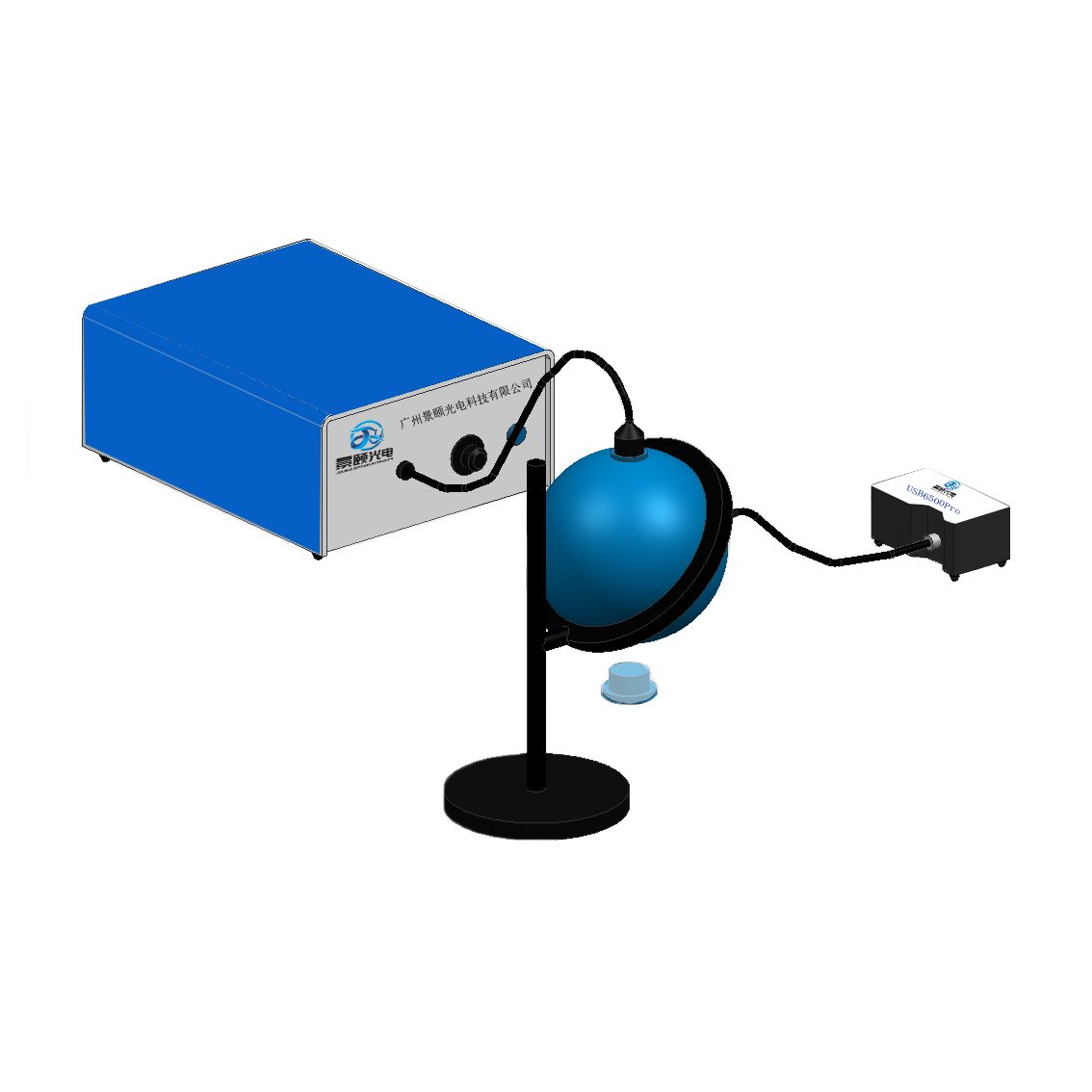
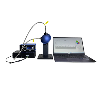
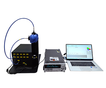
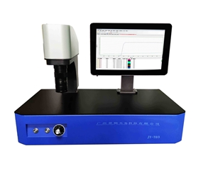
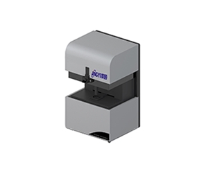
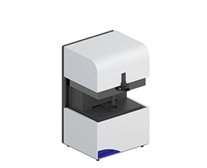
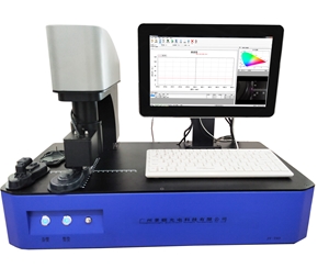
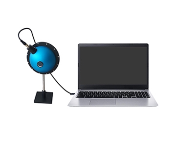
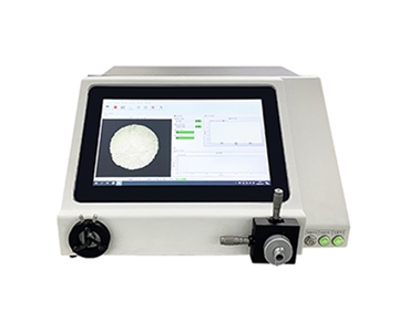
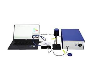
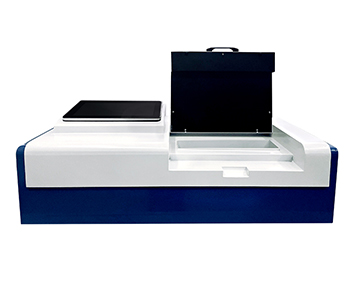
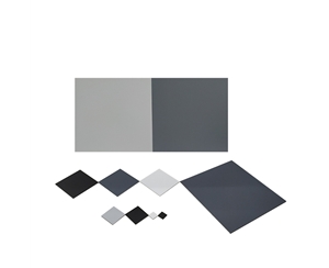
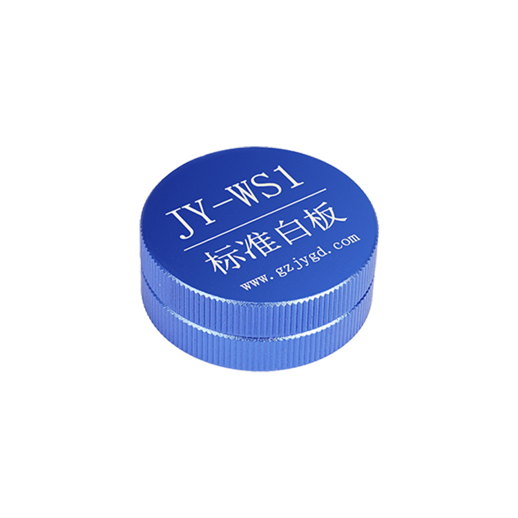
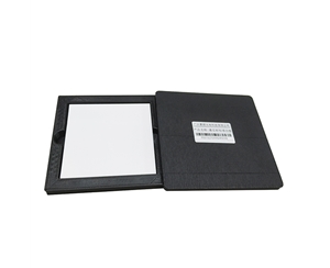
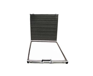
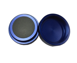
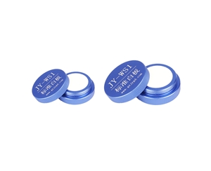
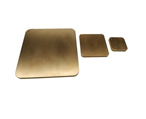
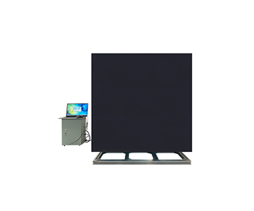
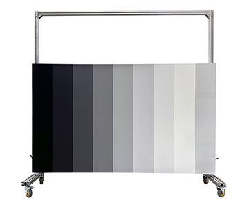
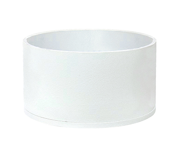
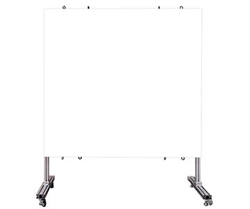
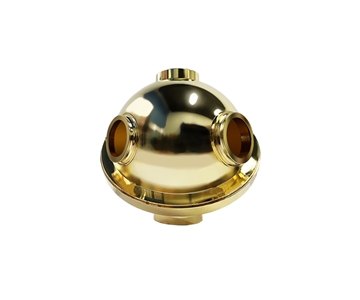
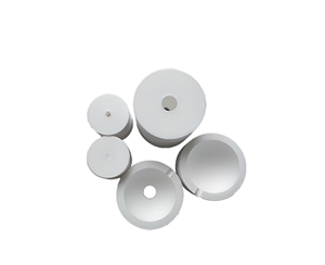
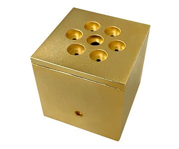
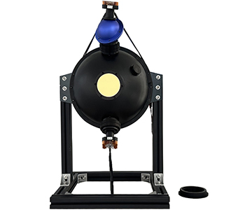
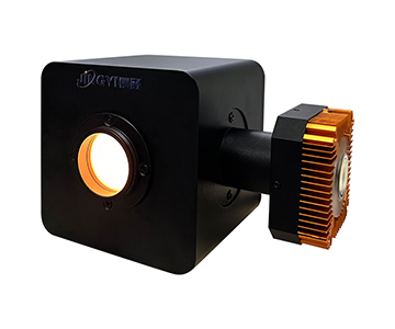
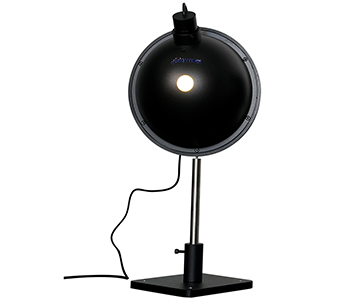
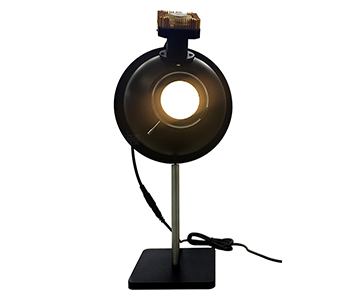
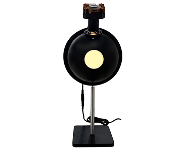
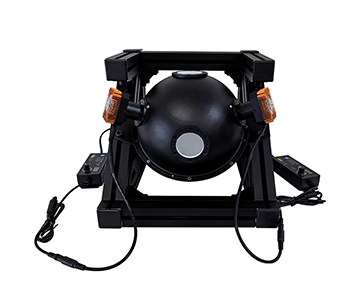
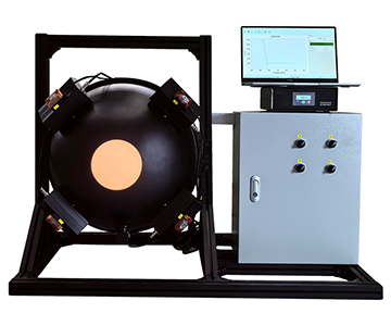
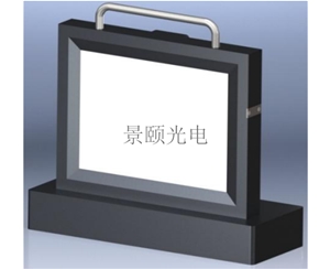
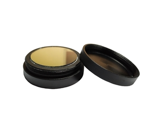
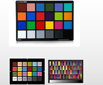
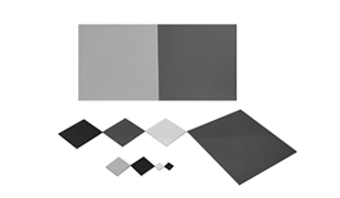
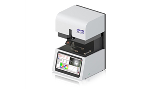
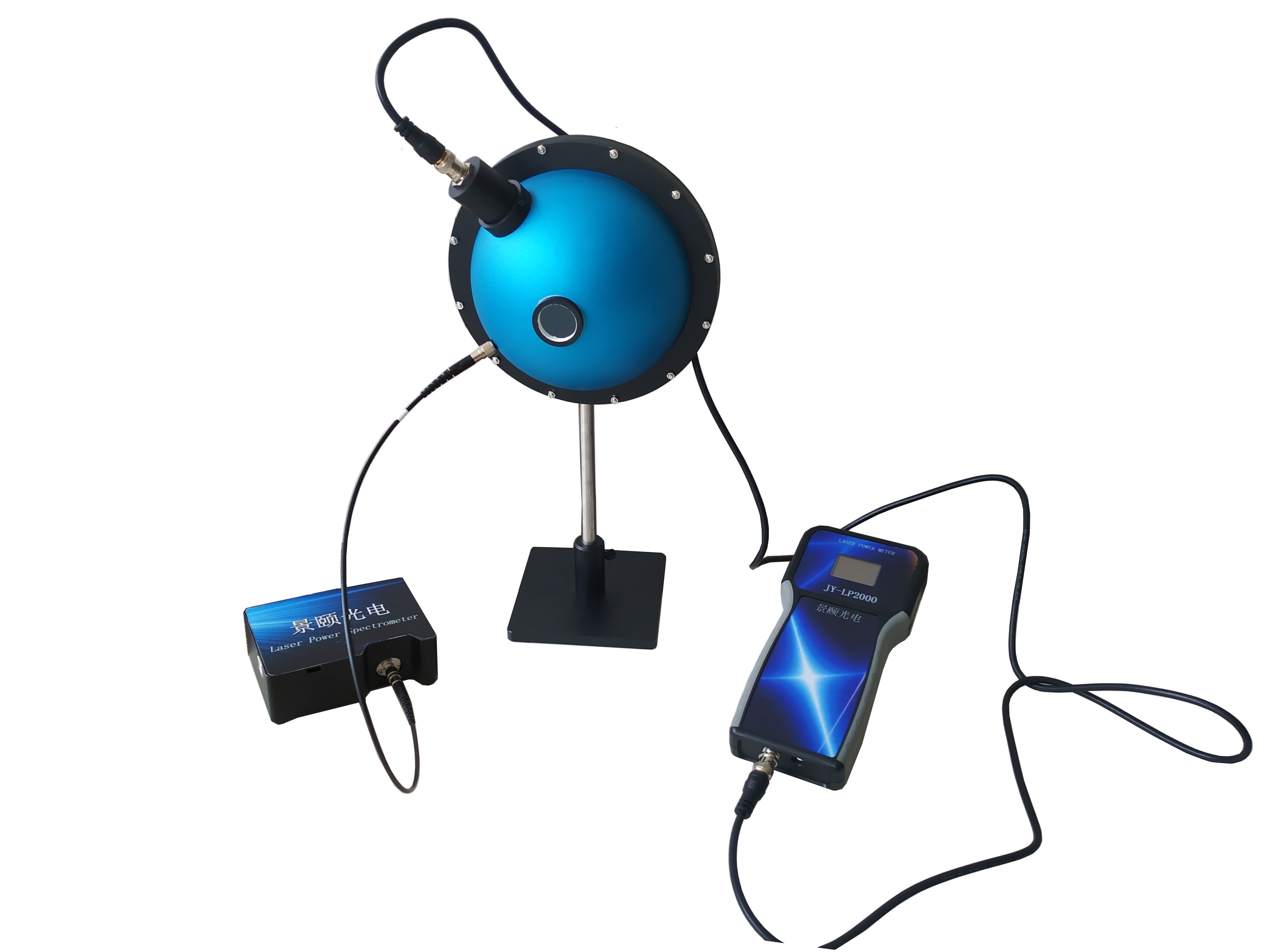
Regardless of architecture, no reflectometer can fully escape systematic errors introduced by non-ideal component characteristics—such as transmission line loss, phase shift, and port mismatch. Raw signal measurements thus yield reflection coefficients inherently deviating from true values—necessitating systematic error calibration. Among single-port reflection calibration methods, OSM (Open-Short-Match) stands out for its high accuracy: using just three standardized calibration standards—open, short, and load—it quantifies all systematic error terms, enabling direct error correction in subsequent measurements. This same calibration logic applies equally well to optical reflectance measurement. Prior to shipment, Jingyi’s JY-F03 undergoes full-range calibration using multiple professionally certified standard reflectance plates. The instrument itself carries third-party metrological certification and supports issuance of official calibration certificates. Upon receipt, users can immediately generate precise reflectance spectra, CIE xy chromaticity diagrams, and CIELAB color values—without performing complex manual calibrations. Even production-line operators with no prior metrology experience can rapidly configure custom functions via the embedded computer’s intelligent operating system—paving the way for industry-wide improvements in measurement accuracy.
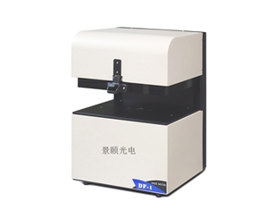
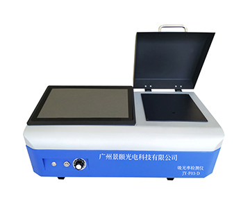
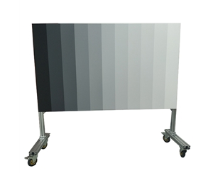
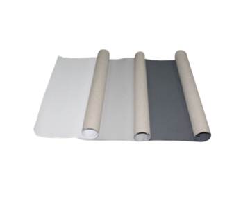
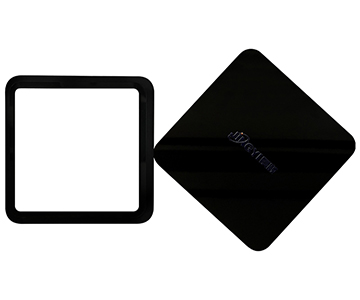
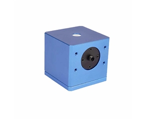
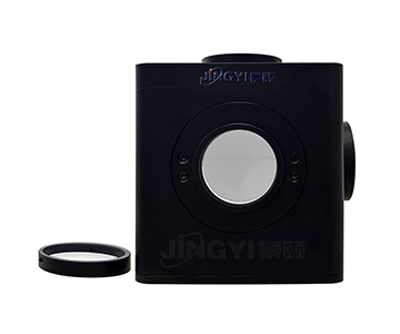
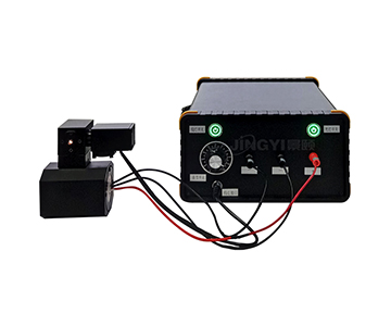
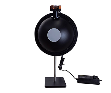
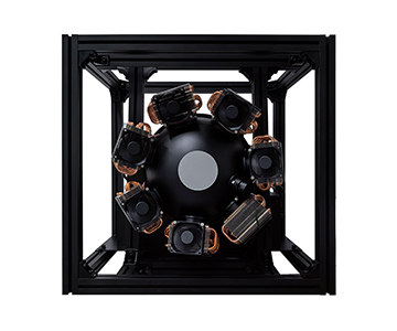
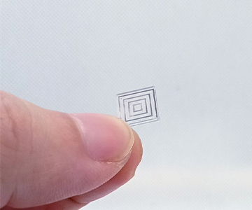
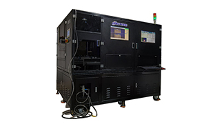
Today, whether it’s miniaturized RF front-end component testing—or reflectance measurement across dozens of specialized applications—including consumer electronics cover glass, automotive reflective parts, paint & ink color sorting, metallic material characterization, mineral/powder analysis, optical component inspection, solar silicon wafer process control, textile performance evaluation, and gemstone authentication—the core principle remains identical: accurate acquisition and rigorous calibration of incident and reflected signals. Many testing solution providers are now cross-pollinating technological strengths from diverse domains. As a fully self-developed product built on wholly indigenous intellectual property, Jingyi’s JY-F03 series not only satisfies reflectance measurement requirements for a wide variety of solid samples and opaque thin films but also enables functional customization per user-specific needs—unlocking even greater potential for precision advancement across the entire testing industry.
#Reflectometer #ReflectanceMeter #GlossMeter #ReflectivityMeter #ReflectanceTester #OpticalReflectanceAnalyzer