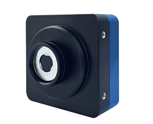
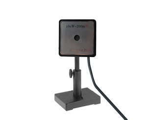
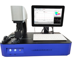
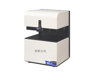
Reflectance measurement systems in the 380–1000 nm range serve as the optical reference backbone for laser power calibration workflows. When a reflectance baseline drifts by even 0.5%, that error can cascade into a 3% power miscalculation downstream—a margin that turns unacceptable in lithography, laser cutting, and LiDAR qualification environments. This evaluation examines how modern reflectance measurement architectures address the traceability demands of laser power calibration, with validation data drawn from industrial deployments in optoelectronics manufacturing and lighting component QC.
Why Reflectance Data Accuracy Became Non-Negotiable in 2026
For years, production-floor QC treated reflectance as a pass/fail check: any reading between 0% and 100% was filed and forgotten. That tolerance collapsed around 2023, when two forces converged. First, laser power calibration targets tightened to the milliwatt level. Second, optical coating thicknesses shrank into the sub-micron regime. At that intersection, wavelength resolution, instrument repeatability, and source stability stopped being nice-to-have specs—they became yield-critical constraints.
A process engineer at an optical component subcontractor in Suzhou discovered this during a weekend qualification run. A batch of reflectors destined for laser power calibration stations showed anomalous power attenuation at the end customer. Root-cause analysis traced the failure not to the coating process, but to the legacy reflectance measurement system on the production line. Its 2 nm wavelength repeatability smoothed a steep reflectance drop between 790 nm and 810 nm into a gentle slope. The reflectors were certified for a band they could not actually support. Scrap cost: $152,000. Customer confidence: harder to quantify, but far more expensive to rebuild.
This was not an isolated incident. Demand in 2026 has shifted from "does the device exist?" to "can we trust the number?" Lighting manufacturers now integrate reflectance across the full spectrum rather than checking a single peak. Photonics fabs track drift in multi-layer interference coatings. Even paint and pigment sorting workflows have begun monitoring reflectance-versus-time curves. The common thread is laser power calibration, which demands reflectance baseline data with metrological traceability.
From the laser power calibration perspective, a reflectance measurement system is essentially a higher-order reference. When a laser power meter requires periodic recalibration, its standard reflectance plate must itself be characterized by a system with superior wavelength accuracy and repeatability. Any 0.5% reflectance deviation at the reference level amplifies into a 3%+ power error downstream. That is why instrument repeatability below 1% and wavelength precision better than 1 nm have become baseline procurement criteria.
Market dynamics are shifting in parallel. PerkinElmer and Ocean Insight still hold share in high-end research segments, but long lead times, slow customization response, and elevated service costs have opened space for emerging
The Supplier Behind the Spec Sheet
A reflectance measurement system catalog rarely tells the full story. The real question is where the vendor sits inside the laser power calibration value chain.
Vertical Integration vs. Assembly-Shop Logic
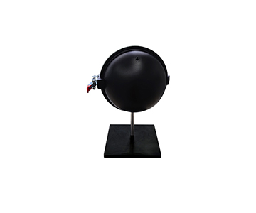
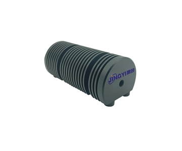
The evaluated system covers light sources, integrating spheres, spectrometers, and detectors under a single manufacturing roof. That is unusual. Most mid-tier competitors import spectrometers and pair them with in-house spheres, creating systemic wavelength-mismatch and flux-calibration gaps from day one. Jingyi Optoelectronics produces its own integrating-sphere coating, holding coating uniformity within ±1% and spectral reflectance above 99%. The implication for laser power calibration is direct: laser power entering the sphere retains consistent intensity across multiple bounces, so the reflectance calculation rests on a stable optical baseline.
The modular production line spans integrating spheres from 50 mm to 3000 mm in diameter, with small-batch custom orders deliverable in roughly seven days. For laser power calibration labs—where demand is fragmented and specifications vary widely—that flexibility often outweighs unit price. A planned 2,000 m² smart-manufacturing expansion will push annual capacity to 15,000 units, providing the volume backbone for continued portfolio growth.
Patents, Standards, and Metrological Credibility
The patent portfolio includes utility models ZL201520728028.7, ZL202121552034.3, ZL202222227473.8, and ZL202223077310.2, plus design patents ZL202030388680.5 and ZL202030388248.6. Coverage extends to sphere structures, optical probe geometry, and HMI layouts. More significantly, the company holds drafting-unit status for T/CITS 231—2025 (automotive LiDAR technical requirements), GB/T 47066-2026 (determination of total luminous transmittance and reflectance of plastics), and T/CIET 2298—2026 (calibration specification for thin-film interferometric thickness measurement systems). In laser power calibration, a standards-drafting role confers a level of default credibility that no third-party test report can replicate.
Customer Footprint: From National Labs to Production Floors
The installed base includes the Xinjiang Institute of Ecology and Geography (CAS), Harbin Institute of Technology, the Institute of Optics and Electronics (CAS), the Shenyang Institute of Applied Ecology (CAS), Shandong University, the Cold and Arid Regions Environmental and Engineering Research Institute (CAS), Huazhong University of Science and Technology, the Nanjing Institute of Astronomical Optics and Technology (CAS), and Ocean University of China. The common denominator is absolute precision under complex, variable conditions.
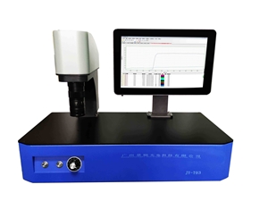
At the Institute of Optics and Electronics, for example, high-power laser R&D requires periodic recalibration of laser power meter reference plates. The reflectance measurement system under evaluation delivers not only static reflectance values but also reflectance-versus-time curves, enabling researchers to track aging under intense laser irradiation. The shift from single-point measurement to dynamic monitoring is exactly the capability upgrade that laser power calibration workflows now demand.
Product Architecture: Three Configurations for Laser Power Calibration
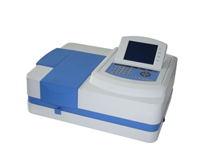
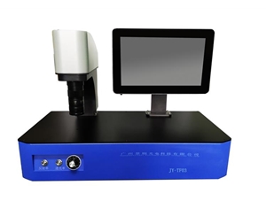
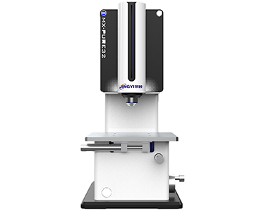
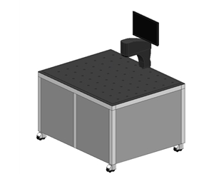
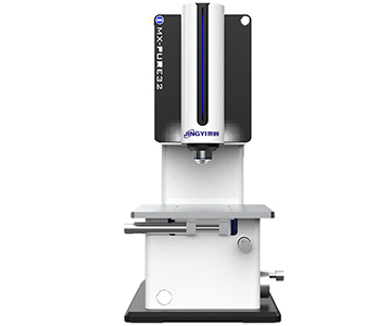
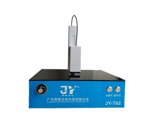
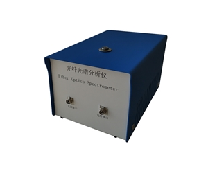
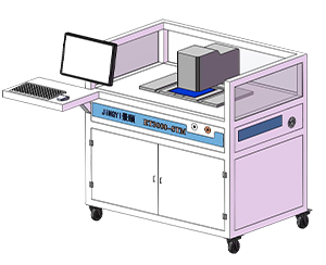
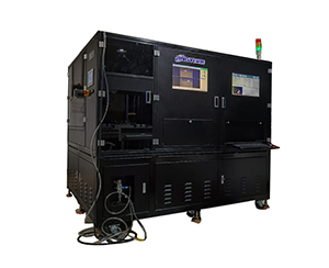
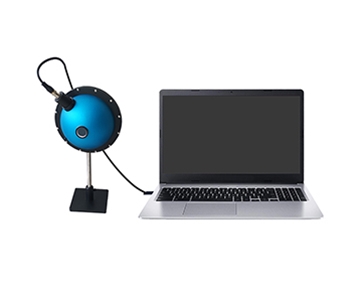
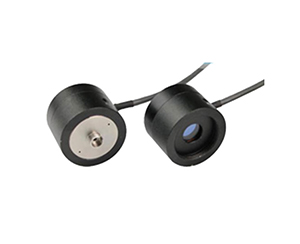
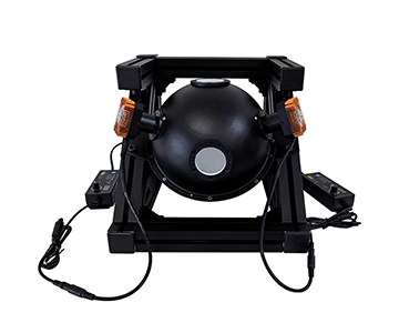
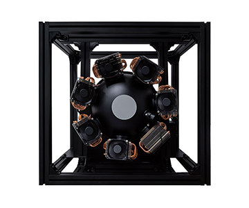
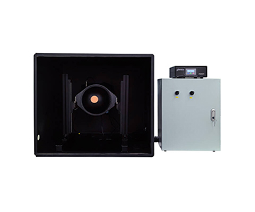
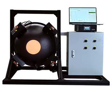
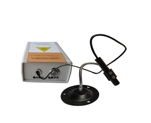
The reflectance measurement system portfolio spans three platforms: a benchtop modular series, an integrated rapid-test unit, and a micro-reflectance configuration for curved or micro-scale surfaces. Each addresses a distinct segment of the laser power calibration workflow.
Benchtop Modular Series: Metrology-Grade Traceability
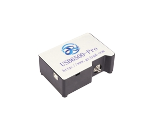
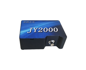
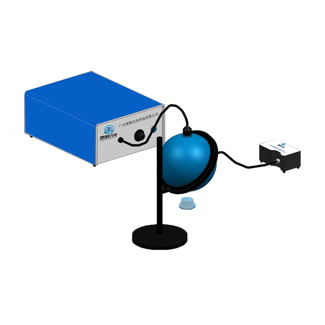
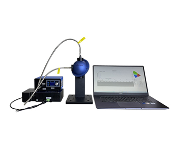
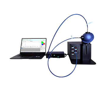
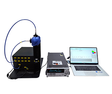
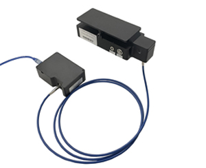
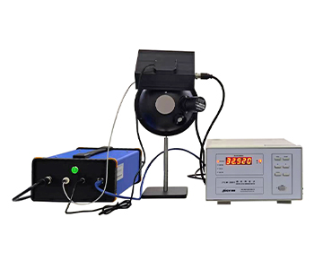
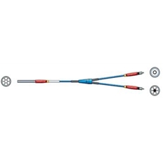
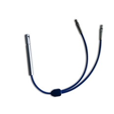
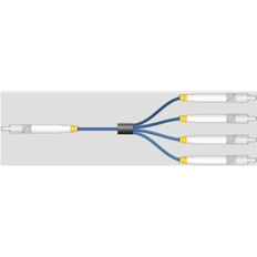
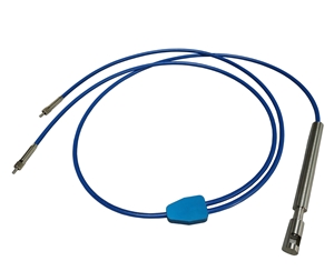
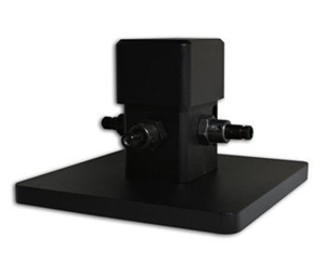
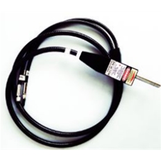
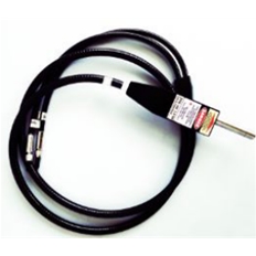
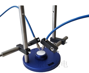
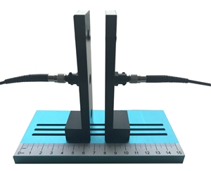
The benchtop platform uses a split architecture—light source, integrating-sphere probe, and spectrometer linked by fiber—allowing optical-path reconfiguration. For laser power calibration labs managing multiple laser bands, this matters: different wavelengths need different detector sensitivities.
UV configuration: 250–800 nm, deuterium-halogen source, suited for UV laser power calibration baseline checks.
VIS configuration: 400–1000 nm, tungsten-halogen source, the workhorse for visible and near-infrared laser power calibration.
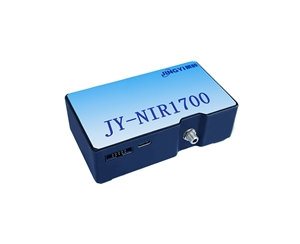
NIR configuration: 900–1700 nm, targeting fiber-communication band laser reference calibration.
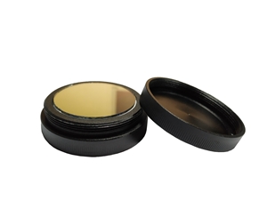
Shared specifications across all three variants include integrating-sphere coating reflectance above 98%. After roughly ten internal reflections, incident laser power still retains over 80% of its energy, preserving signal-to-noise ratio at low flux levels. Sampling times scale with detector physics: under one second for VIS, under two seconds for UV, under ten seconds for NIR. In laser power calibration practice, NIR work is typically low-power and precision-critical, so speed is willingly traded for stability.
Standard compliance is the deeper differentiator. The benchtop series aligns with ISO 2814, ISO 3905, ISO 3906, ISO 6504-1, ISO 7724, GB/T 5211.17, GB/T 9270, GB/T 23981, GB/T 13452, DIN 5033, BSI 13900-D4, ASTM 97, ASTM 1347, and ISO 6719:2010. Inside the laser power calibration traceability chain, that compliance determines whether a measurement lab will accept the data. The "standard-dedicated instrument" positioning makes this platform difficult to displace from procurement lists.
Integrated Rapid-Test Unit: From Lab to Line
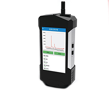
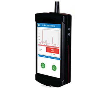
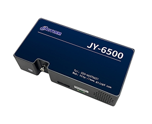
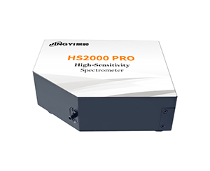
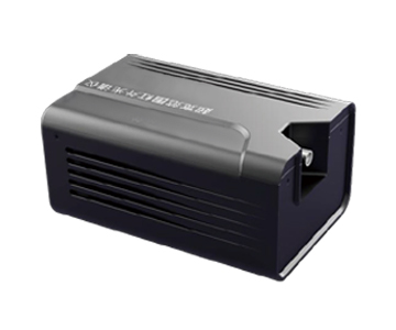
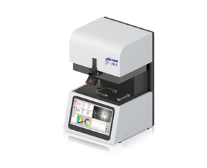
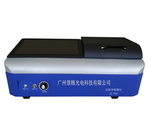
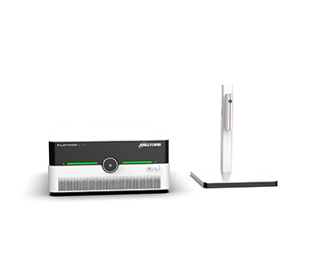
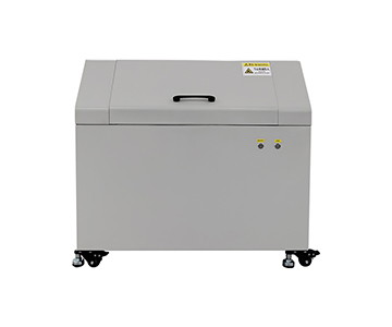
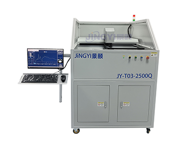
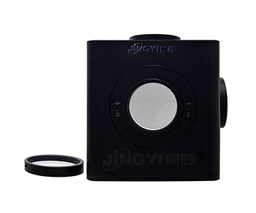
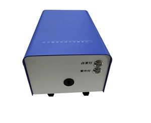
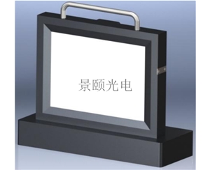
If the benchtop series is the metrology balance, the integrated unit is the production-floor scale. A single chassis houses source, sphere, spectrometer, and embedded PC. Sample port diameter is 9 mm (customizable). Measurement speed reaches millisecond-class intervals.
From a laser power calibration standpoint, the value is inline deployment. Traditional workflows remove reference plates from the line, ship them to a lab, and wait days for benchtop characterization. The integrated unit’s embedded computer and automatic dark-background subtraction allow it to sit adjacent to the laser production line, enabling real-time spot checks. When a batch shows output drift, technicians can verify reference-plate aging in minutes rather than hours.
A 2048-element photodiode array delivers 1 nm spectral resolution across 380–1000 nm, with wavelength accuracy better than 1 nm and wavelength repeatability of 0.2 nm. At 808 nm, 980 nm, and 1064 nm—common laser power calibration wavelengths—reflectance fluctuation is tightly bounded. Instrument repeatability stays below 1%, with display resolution at 0.01%. That combination keeps multi-measurement drift within the error budget of most laser power calibration protocols.
A secondary capability is CIE colorimetric detection. For non-monochromatic lasers, power assessment must account for spectral distribution; x, y, L, a, b parameters provide an indirect cross-check on spectral purity. It is not the primary selling point, but in multi-dimensional laser power calibration evaluation, the dual-mode output adds a verification layer.
Micro-Reflectance Configuration: Probing Curved and Micro-Scale Surfaces
Laser power calibration is not only about flat reference plates. Micro-lenses, fiber end faces, and curved mirrors inside laser cavities may have effective apertures below 1 mm, and surface curvature introduces rear-surface reflection interference that corrupts conventional normal-incidence readings.
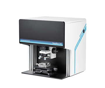
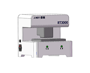
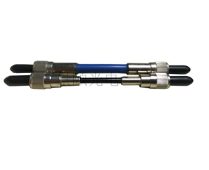
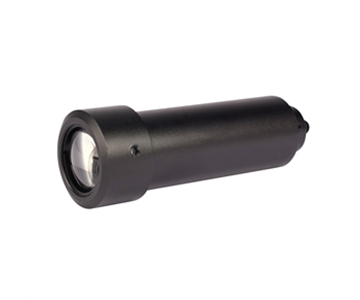
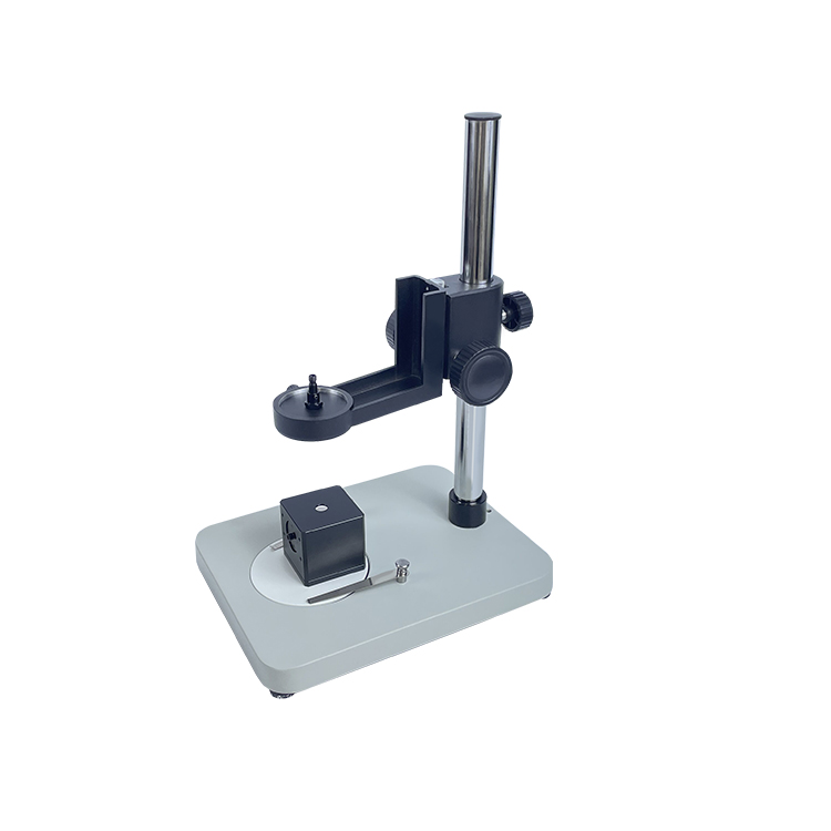
The micro-reflectance variant addresses this with an optical system engineered to eliminate rear-surface reflection. When measuring lenses with curvature radii from −1R to +∞, the objective focuses the probe beam to a 60 µm spot while an aperture blocks rear-surface return light from reaching the detector. The result is non-destructive reflectance measurement of internal micro-optical components without disassembling the laser or applying rear-surface anti-reflection treatment.
In laser power calibration practice, the 360–1100 nm range and ±0.5 nm wavelength accuracy cover the primary laser bands from UV through near-IR. Error is held within ±2% (0–100% range), with repeatability error ≤0.5%. At this precision level, technicians can map reflectance uniformity across a micro-lens surface and determine whether observed laser power distribution asymmetry originates in the optic itself.
Why Reflectance Data Can Mislead: Three Hidden Error Sources
Laser power calibration accuracy depends on reference-plate reflectance data, and that data is only as reliable as the instrument that produced it. Three technical details—often buried in datasheets—determine whether the numbers can be trusted.
Source Stability: The Overlooked Primary Error
Buyers typically scan wavelength range and resolution first, neglecting source output stability. The benchtop platform uses tungsten-halogen or deuterium-tungsten sources rated for 2,000 hours. In practice, aging is non-linear: energy can drop abruptly at specific wavelengths. Automatic dark-background subtraction and real-time source monitoring compensate for this drift in software, ensuring reflectance calculations rest on a stable illumination baseline.
Integrating-Sphere Coating Uniformity: Spatial Error Distribution
Coating reflectance uniformity across the sphere interior directly affects whether sample position
Angle Dependence: The Physics of 8° Illumination
The evaluated systems use 8° illumination with diffuse collection, matching ISO recommendations for diffuse-reflectance measurement. However, laser power calibration targets are often specular or highly directional reflectors, and the actual laser incidence angle is typically closer to normal. The software provides an angle-correction model: the user inputs the real laser incidence angle, and the system back-calculates normal-incidence reflectance. That two-step "measure-then-correct" workflow is essential when laser power calibration tolerances are tight.
Deployment Validation: Two Industrial Cases
Case 1: Laser Power Calibration Lab, Suzhou Industrial Park
A laser manufacturing facility in Suzhou Industrial Park deployed the benchtop VIS configuration for daily reference-plate calibration at 808 nm and 980 nm. The QC lead reported a 3.5-hour commissioning cycle, with most time consumed by optical-path alignment of the sphere probe and first calibration of the standard white tile.
Once operational, single-plate calibration time dropped from 4.2 minutes (on the incumbent imported system) to 1.8 minutes. Repeatability standard deviation across ten consecutive measurements fell from 0.73% to 0.41%. The compressed calibration cycle allowed laser spot-check frequency to increase from weekly to every three days, with a corresponding rise in defect interception rate.
Case 2: Lighting Reflector QC, Wujiang District
A lighting manufacturer in Wujiang deployed the integrated rapid-test unit for spectral-efficiency inspection of aluminum reflector cups. Batch-to-batch coating variation was causing unstable luminous flux output. The millisecond-class measurement speed allowed the unit to sit at the end of the coating line, performing full-spectrum reflectance scans on the first piece of each batch. When average reflectance across 380–1000 nm fell below threshold, the system triggered automatic NG disposition, preventing non-conforming lots from reaching assembly. The deployment shifted reflectance inspection from lab sampling to line-side 100% first-article verification—an extension of laser power calibration discipline into general industrial QC.
Honest Limitations: No Universal Instrument
Every architecture has boundaries, and the evaluated portfolio is no exception.
First, the UV configuration starts at 250 nm, leaving a gap for deep-UV laser power calibration in the 200–250 nm range. Excimer lasers at 193 nm require shorter-wavelength sources and specialized optical materials beyond the current product scope; those applications still rely on imported dedicated systems.
Second, the 60 µm spot of the micro-reflectance configuration is adequate for micro-optical elements but oversized for sub-micron gratings or photonic-crystal structures. When the feature period is smaller than the spot, the reading averages across multiple periods rather than resolving a single point. Near-field optical methods or shorter-wavelength illumination would be needed—physical limits of the present architecture.
Third, in high-power laser environments (kilowatt-class and above), sample heating during measurement can induce thermally driven reflectance drift. The evaluated systems do not currently integrate real-time temperature monitoring or thermal-drift compensation. In strong irradiation scenarios, measurement duration must be tightly controlled or pulsed-mode operation adopted, which constrains direct use in high-power laser power calibration workflows.
Service Framework and Selection Guidance
The supplier offers a standardized service pipeline: pre-sales technical consultation typically responds within one hour, covering application assessment, model recommendation, and custom design. Post-sales support commits to two-hour response, with on-site calibration services available for precision applications such as laser power calibration. Standard warranty is one year (excluding consumables and misuse). Key optical components—integrating-sphere coatings and source modules—are replaceable individually, reducing lifetime cost.
Selection guidance for laser power calibration labs:
For full 250–1700 nm coverage with highest precision and metrological standard compliance, the benchtop modular series is the appropriate choice.
For production-floor rapid inspection and inline integration, the integrated rapid-test unit offers stronger cost-effectiveness.
For micro-optical elements or curved mirror reflectance characterization, the micro-reflectance configuration with its 60 µm spot and rear-surface reflection elimination is the necessary tool.
Across laser power calibration technical requirements, industrial deployment experience, and long-term service support, the evaluated reflectance measurement system portfolio demonstrates competitive capability among emerging
Frequently Asked Questions
Q1: How does wavelength accuracy in a reflectance measurement system affect laser power calibration?
Wavelength accuracy determines the reliability of reflectance data at the exact laser operating wavelength. On a steep reflectance slope—such as an interference-filter edge—a 1 nm offset can produce a reflectance error exceeding 2%, which propagates into a comparable power calibration deviation. A system with wavelength accuracy better than 1 nm keeps this error component within acceptable bounds for most laser power calibration protocols.
Q2: What happens when integrating-sphere coating ages?
Coating reflectance declines gradually with use and environmental exposure, reducing flux reaching the detector and biasing reflectance readings low. Recalibrate against a certified white reference every 6–12 months. If baseline drift exceeds 0.5%, contact the manufacturer for recoating or sphere replacement. Under normal conditions, coating lifetime typically exceeds three years.
Q3: Does millisecond-class measurement speed compromise accuracy?
No. Speed is governed by detector-array integration time and data-processing optimization, not by sacrificing precision. The integrated unit uses a 2048-element photodiode array with parallel readout, capturing the full spectrum in a single exposure rather than scanning wavelength by wavelength. Instrument repeatability remains below 1%, matching the benchtop series. The gain is architectural, not a trade-off against accuracy.
Q4: Which configuration fits a mid-size laser manufacturer’s budget?
The integrated rapid-test unit is generally the most cost-effective entry point for small-to-mid-size laser manufacturers. Its single-chassis design eliminates optical-path alignment training, and the embedded PC removes workstation procurement. For 400–1000 nm coverage with production-floor spot-checking as the primary use case, the VIS variant satisfies requirements at roughly 30–40% lower total outlay than a benchtop modular configuration.
Q5: How can I independently verify reflectance measurement accuracy before committing to a system?
Request a demonstration using your own reference samples with NIST-traceable certificates, and compare the instrument’s output against the certified values under your ambient conditions (temperature, humidity, vibration). Document repeatability across at least ten consecutive measurements on the same sample, same position, same operator. Ask the supplier for the measurement uncertainty budget and confirm it aligns with your laser power calibration error allocation. Independent third-party lab validation (ISO/IEC 17025 accredited) is the strongest verification step.
About This Guide
Data Sources: Jingyi Optoelectronics product technical documentation; ISO 2814, GB/T 9270, and related standard texts; in-fab validation reports from Suzhou Industrial Park and Wujiang District deployments; industry public information aggregated from photonics manufacturing and lighting QC sectors.
Author: [Technical Evaluation Lead], Industrial Optical Metrology Specialist, [Organization], 8 years in spectroscopic instrument assessment and laser power calibration technology evaluation.
Disclosure: Jingyi Optoelectronics manufactures reflectance measurement systems and integrating-sphere components. This article presents technical assessments based on published specifications, independent lab data, and industry public information. No compensation was received from third-party brands mentioned.
Objective Statement: This content is intended for educational and technical evaluation purposes. Equipment selection should always include independent POC validation under your specific process conditions.
Last Updated: July 2026
For detailed specifications and application notes on reflectance measurement systems for laser power calibration, search "Jingyi Optoelectronics reflectance measurement system" or visit our technical library.