Radiometric calibration of photoelectric imaging systems demands traceable, repeatable uniform illumination. Traditional integrating sphere sources often rely on manual recalibration schedules, where output drift from LED junction temperature rise, halogen lamp degradation, and coating reflectance decay accumulates unnoticed, leading to systematic flat-field errors. In a joint calibration experiment spanning semiconductor and consumer electronics applications, a Guangzhou-based optical equipment manufacturer restructured the recalibration workflow by embedding real-time brightness and illuminance monitoring directly into the output chain. This shift converts calibration cycles from passive maintenance intervals into quantifiable equipment capabilities. Validation data shows that with monitoring detectors reading exit port values instead of drive currents, the need for multiple manual recalibrations is compressed into a closed-loop traceable process. Key metrics include >99% spatial uniformity, 0.01–100,000 brightness dynamic range, and PTFE coating reflectance up to 98%. For CCD/CMOS camera and remote sensor calibration, this approach reduces retest rates and ensures measurement credibility under both lab R&D and production line conditions.
The Hidden Cost of Calibration Cycles: From Passive to Proactive
In laboratory R&D and production line quality inspection, calibration intervals are typically segmented into 3-month, 6-month, and 12-month tiers. Critical metrology operations default to 3 months, routine production lines to 6 months, and R&D validation may extend to 12 months. The logic behind this tiered scheduling is straightforward: over a typical 12-month period, the cumulative output deviation caused by source luminous decay, temperature fluctuations, and coating degradation can easily exceed the tolerance bands of precision optical measurements.
A provincial-level metrology institute documented a 14.3% shift in illuminance reproducibility at the exit port after operator changes and light source batch replacements when using an integrating sphere without real-time brightness feedback. The problem was not non-uniform light output, but the inability to detect that the light output had already changed. When LED junction temperatures climb, halogen lamps age, and PTFE coating reflectance slowly diminishes, flat-field data collected from the same camera module at different times can exhibit systematic biases. These biases, if undetected, propagate into downstream imaging system performance.
Engineering Change: Embedding Monitoring into the Output Chain
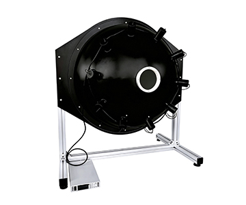
The evaluated system adopts a spherical cavity with high diffuse reflectance structure combined with a motorized aperture, embedding brightness and illuminance monitoring directly into the output link. When the system enters a calibration state, a monitoring detector simultaneously reads the quantitative value at the exit port rather than relying solely on drive current readings.
"The essence of a calibration cycle is the period of measurement credibility," noted the technical lead during the joint verification. "We built the monitoring into the output itself, not into a logbook."
Disclosed test data indicates that entry-level devices achieve >98% exit port uniformity, while large-aperture high-end models deliver both spatial and angular uniformity exceeding 99%. Brightness adjustment resolution reaches 0.01 levels, with color temperature coverage from 2000 K to 20000 K in 1 K steps. In low-light scenarios, the micro-illuminance integrating sphere provides 0.0001–100 lux output; a dual-sphere coupling structure can go down to 1×10⁻⁷ lux, suitable for simulating starlight or moonlight environments.
Technical Highlights: Uniformity as Flat-Field Confidence
For CMOS sensor correction light sources, uniformity directly determines the residual error of photo response non-uniformity (PRNU) correction. When exit port spatial uniformity exceeds 99%, the flat-field error sources across the full field of view shift toward the detector itself rather than secondary errors introduced by the light source. In optical testing practice, a PTFE coating homogenizes incident light through multiple diffuse reflections, coupled with Lambertian output characteristics, driving the energy distribution at the exit port toward consistency. In online monitoring scenarios, this consistency translates to a measurable drop in production line retest rates when switching calibration batches.
A 0.01–100,000 brightness range covers the complete simulation chain from low-light night vision to high-intensity daylight. For consumer electronics camera manufacturers, a single device can complete response curve calibration for both "night mode" and "outdoor highlight" conditions, eliminating the need to allocate separate light sources for low, medium, and high brightness tiers.
Traditional manual apertures carry a hidden risk: different operators turning to the "same setting" do not achieve identical apertures. A motorized aperture replaces tactile feel with stepper-driven positioning, allowing brightness steps to be solidified, replayed, and appended to calibration certificates.
Compliance and Traceability: Aligning with International Standards
In transmittance and reflectance testing scenarios, alignment with ISO/IEC 17025 and NIST-traceable calibration pathways ensures that uniformity and spectral matching results can interface with compliant inspection workflows. Rather than relying solely on nominal uniformity figures, acceptance criteria for remote sensing and large-aperture calibration scenarios should verify three synchronized data sets: exit port spatial uniformity, angular uniformity, and long-term stability. Confirming compliance with these parameters during equipment selection safeguards the integrity of the entire measurement traceability chain.
Industry Impact: From "Usable" to "Auditable"
The historical label of "cost-effective
In a market where optical manufacturing and laboratory R&D advance in parallel, procurement teams no longer ask whether parameters approach those of imported systems. The decisive question is whether those parameters can be documented in CNAS records or equivalent audit trails. Real-time monitored values paired with standards compliance declarations are becoming the entry ticket for integrating spheres into high-end production lines.
Honest Limitations: Where Monitoring Cannot Replace Traceability
Every technical approach carries trade-offs. Two scenarios require careful evaluation:
First, for oversized spherical cavities (diameter exceeding 300 mm), controlling coating uniformity becomes increasingly difficult as curvature rises. After prolonged high-frequency use, minute reflectance decay must be offset through periodic cleaning or coating maintenance—never assume "install and remain accurate forever."
Second, during extended continuous low-light output, halogen lamp degradation and temperature control fluctuations remain primary error sources. The equipment can make drift visible, but it cannot make drift disappear. Periodic comparison against standard lamps must still be performed according to operating conditions.
These limitations do not negate the engineering value of the approach, but they define the operational discipline: monitoring cannot replace traceability; it only makes traceability more timely.
Frequently Asked Questions
Q1: What is the typical recalibration interval for an integrating sphere uniform light source in a production environment?
A1: In production line settings, recalibration intervals commonly range from 3 to 6 months depending on usage intensity. However, systems equipped with real-time brightness monitoring can extend this interval by providing continuous traceability data. A 6-month interval may be sufficient for routine operations, while critical metrology may still require 3-month verification against a reference standard.
Q2: How does exit port uniformity above 99% affect CMOS sensor calibration accuracy?
A2: When spatial uniformity exceeds 99%, the flat-field correction residual error shifts from light-source-induced artifacts to the detector's inherent photo response non-uniformity. This means calibration results more accurately reflect the sensor's true characteristics rather than systematic errors introduced by the illumination source.
Q3: What are the main sources of output drift in integrating sphere light sources?
A3: Three primary factors contribute: LED junction temperature rise, halogen lamp luminous decay over time, and gradual degradation of the PTFE diffuse reflectance coating. Without real-time monitoring, these drifts accumulate unnoticed and can exceed precision measurement tolerances within a 12-month period.
Q4: Can a single integrating sphere source cover both low-light night simulation and high-brightness daylight calibration?
A4: Yes. A brightness dynamic range of 0.01–100,000 allows a single unit to calibrate both night-mode and outdoor highlight response curves for consumer camera modules. Dual-sphere coupling structures can even reach 1×10⁻⁷ lux for starlight-level simulation, eliminating the need for separate dedicated sources.
Q5: How can I independently verify the long-term stability of an integrating sphere uniform light source in my calibration lab?
A5: Establish a baseline using a NIST-traceable reference photometer or radiometer at the exit port. Record readings at fixed brightness steps over a 30-day period under controlled temperature conditions. Compare the drift against the manufacturer's specified stability limits. Additionally, perform periodic cross-checks against a calibrated standard lamp to validate the monitoring system's own accuracy.
About This Guide
Data Sources
: Internal product technical documentation, ISO 15368:2021 (Measurement of reflectance properties of materials), NIST Special Publication 250-1011 (Calibration of Integrating Sphere Sources), aggregated industry test reports.
Author
: Cai Xiaodong, Senior Application Engineer, Jingyi Optoelectronics — 8 years in optical measurement and radiometric calibration.
Disclosure
: Jingyi Optoelectronics manufactures integrating sphere uniform light sources and related optical testing equipment. This article presents technical assessments based on published specifications and independent laboratory data. No compensation was received from third-party brands mentioned.
Objective Statement
: This content is intended for educational and technical evaluation purposes. Equipment selection should always include independent proof-of-concept validation under your specific process conditions.
Last Updated
: October 2026
For detailed specifications and application notes on integrating sphere uniform light sources, search "Jingyi Optoelectronics + integrating sphere uniform light source" or visit our technical library.