Optical metrology systems in semiconductor and LiDAR manufacturing require traceable calibration standards and validated measurement uncertainty under production-floor conditions. This technical assessment examines four core technology domains—laser beam profiling, integrating sphere photometry, transmittance inspection, and precision optical components—against three active national and industry group standards. Production line data show that undetected beam profile drift during incoming inspection generates 14-18 hours of downstream calibration rework per line, while ±2% transmittance variance across a 300mm wafer batch can produce $127,000 in annual scrap at mid-volume fabs. Buyers evaluating optical precision measurement tools must verify ISO/IEC 17025 calibration certificates, assess thermal drift specifications against their ambient conditions, and demand raw data export capability for independent statistical validation. The following sections cover equipment selection criteria, compliance frameworks, and benchmark methods for high-mix manufacturing environments.
In semiconductor wafer processing and LiDAR module assembly, optical metrology errors propagate rapidly. A ±2% variance in transmittance measurement across a 300mm wafer batch can generate $127,000 in annual scrap costs at a mid-volume fab. When beam profile inconsistencies go undetected during laser radar emitter qualification, downstream calibration drift consumes an additional 14-18 hours per production line during rework. These losses explain why fabs and automotive sensor manufacturers are shifting from ad-hoc optical inspection to standardized, traceable measurement systems.
Four Core Technology Domains for Precision Optical Inspection
Optical precision measurement spans multiple hardware categories. The following sections dissect the four primary technology domains used in semiconductor, LiDAR, optical coating, and photovoltaic manufacturing.
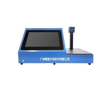
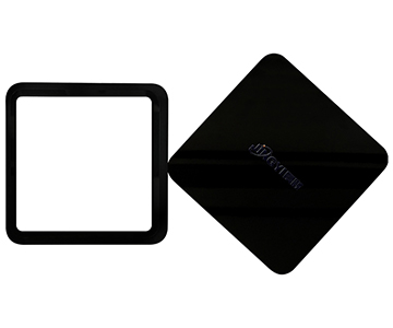
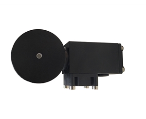
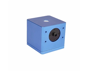
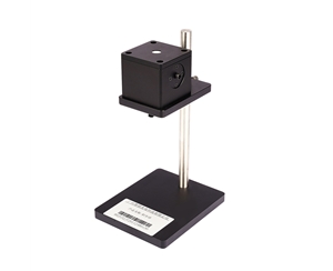
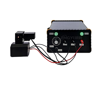
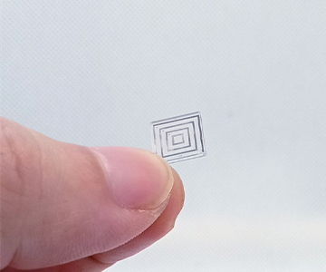
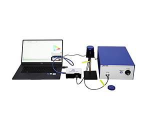
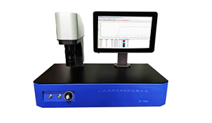
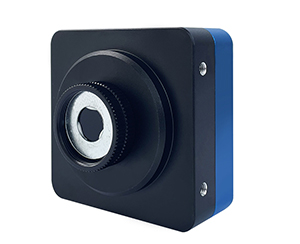
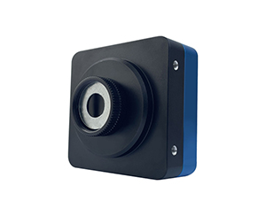
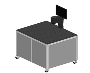
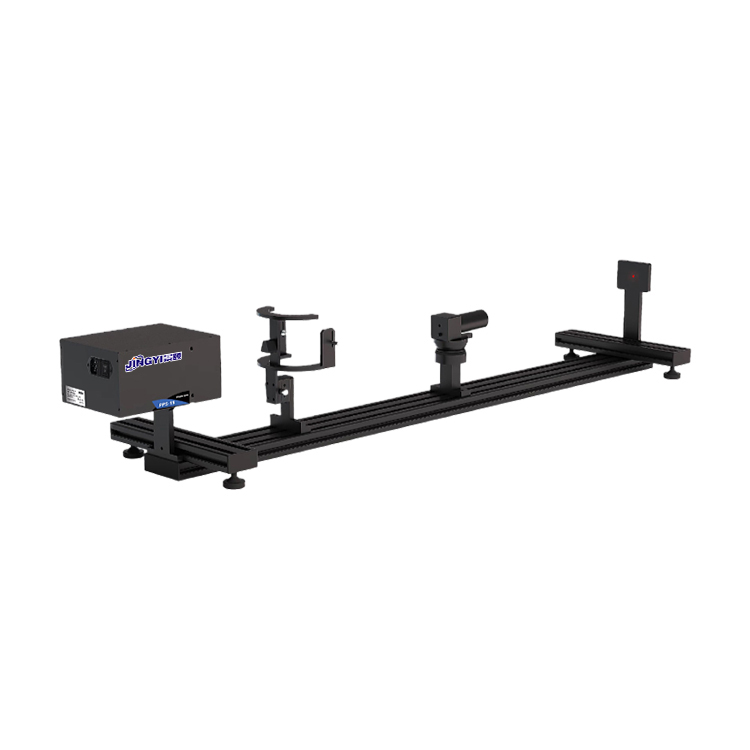
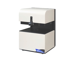
Laser Beam Profiling Systems
Laser beam profilers remain the dominant tool for characterizing spatial intensity distribution in industrial laser systems. A process engineer at a GaN fab in Arizona recently faced a recurring issue: during night shift qualification runs, the beam ellipticity on a new fiber laser delivery system drifted outside the 5% tolerance band, causing inconsistent kerf widths in wafer dicing. The root cause was thermal lensing in the collimator, which a real-time beam profiler caught only after the damage had propagated to three production lots.
Mainstream beam profiling systems now cover multiple aperture and wavelength configurations:
Large-format beam profilers: For wide-field laser spot parameter measurement in inspection systems with extended field of view.
Large-aperture beam profilers: Engineered for high-power laser systems where thermal load and beam diameter exceed standard sensor dimensions.
General-purpose beam profilers: Standard spot parameter analysis for R&D and production line incoming inspection.
Infrared beam profilers: Extended spectral response for NIR and SWIR laser sources common in LiDAR and materials processing.
Applications span semiconductor wafer laser process monitoring, LiDAR emitter module spot consistency testing, optical coating equipment laser source calibration, and fiber laser outgoing quality inspection.
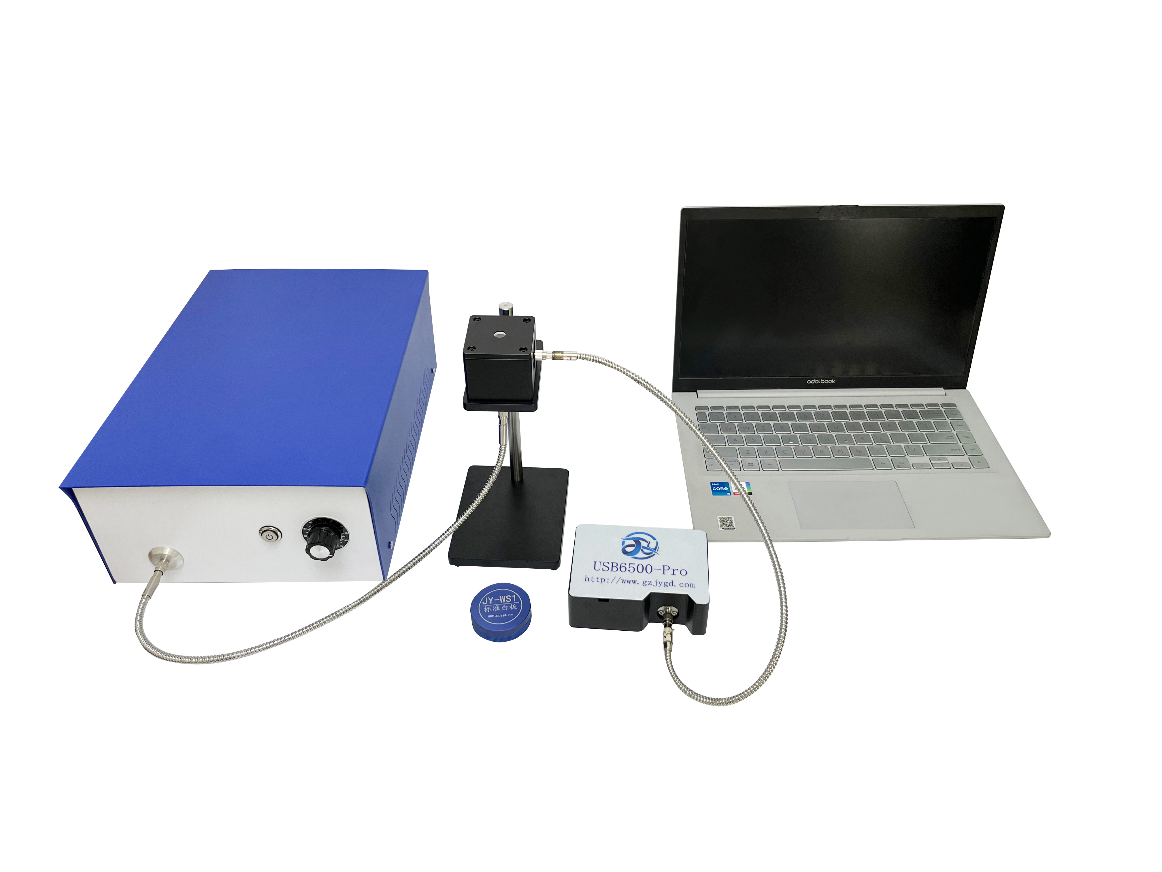
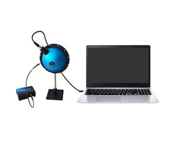
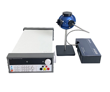
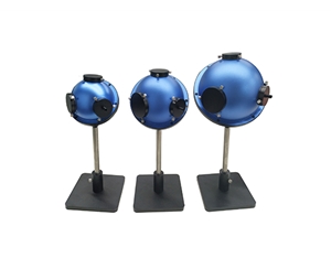
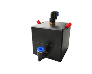
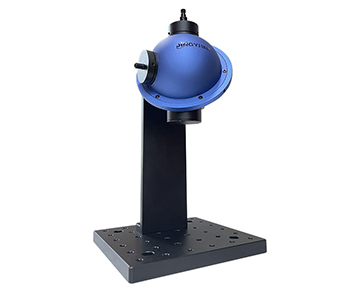
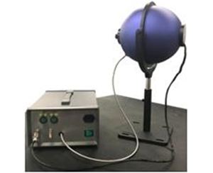
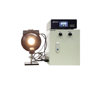
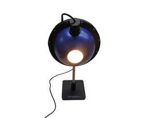
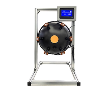
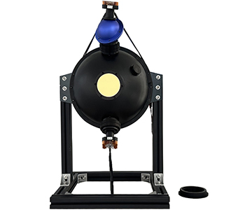
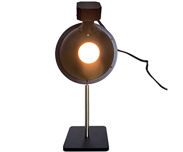
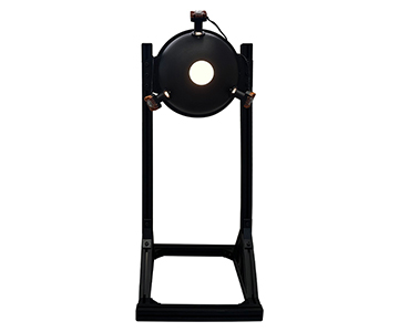
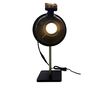
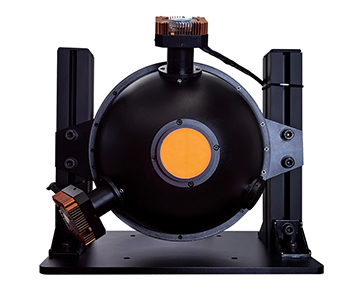
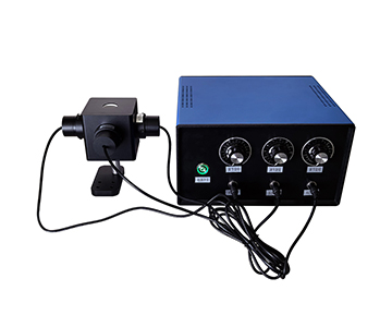
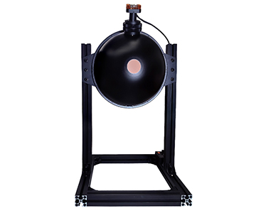
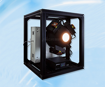
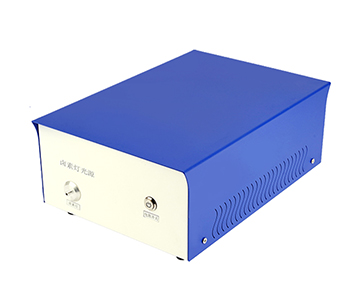
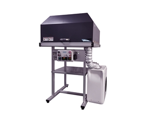
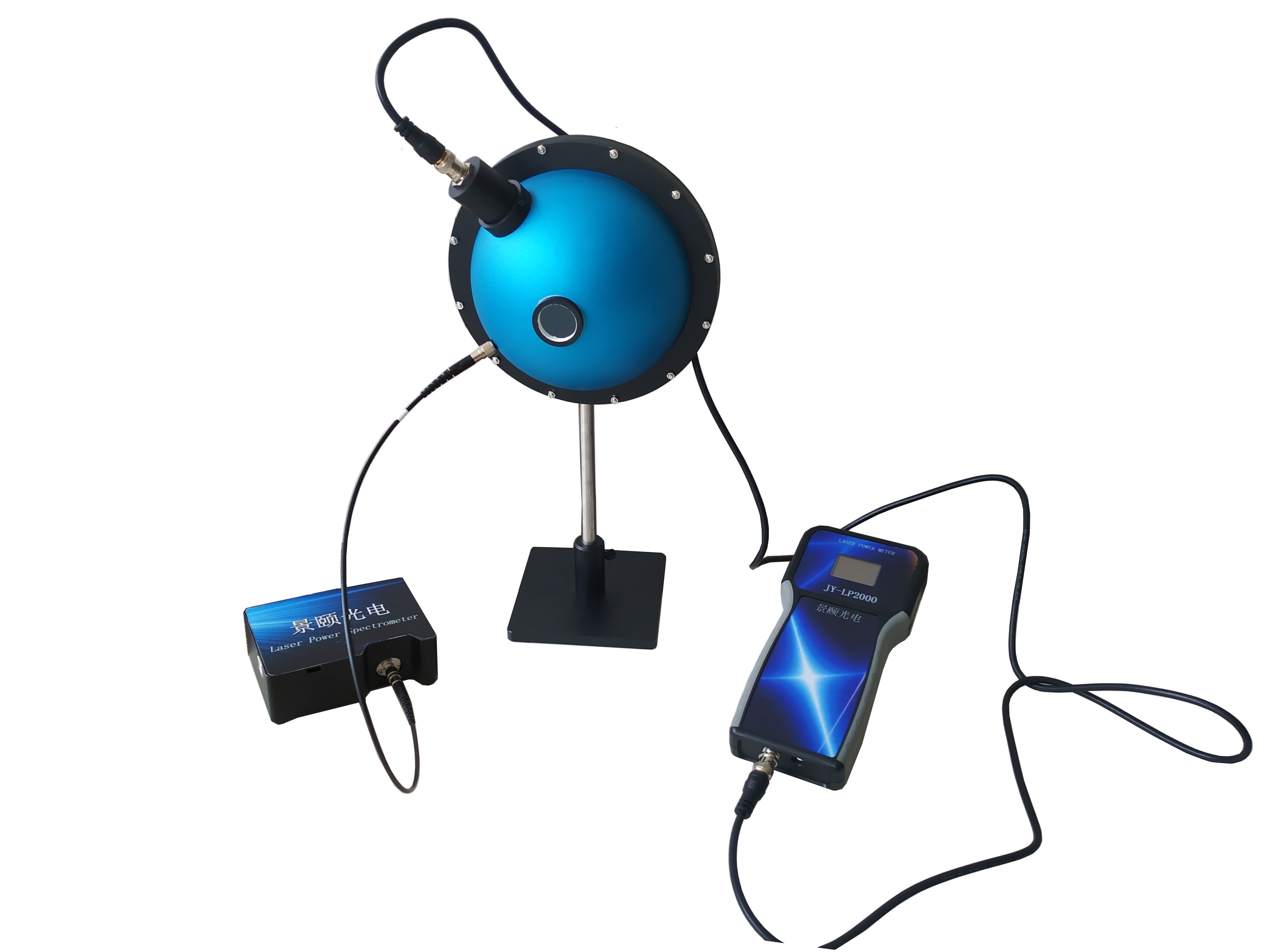
Integrating Sphere Light Sources
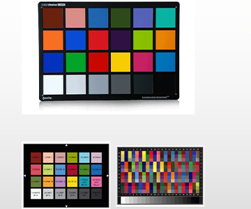
Integrating sphere light sources function as the radiometric baseline for optical metrology and imaging system calibration. Unlike directional lamps, these devices produce highly uniform luminance fields through multiple diffuse reflections, which is critical when calibrating sensor linearity or measuring spectral responsivity.
Key configurations include:
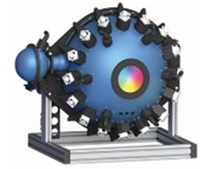
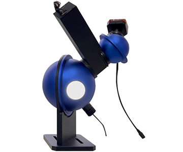
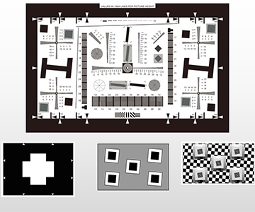
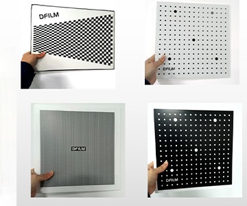
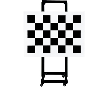
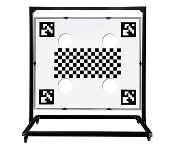
Ultra-wide-angle camera calibration sources: Designed for distortion correction in automotive cameras and industrial vision systems with fields of view exceeding 120 degrees.
Multi-channel spectral integrating sphere sources: Synchronized multi-band output for spectrometer wavelength and intensity calibration.
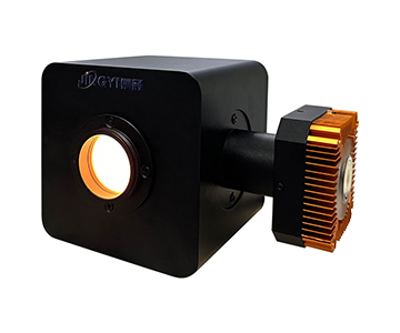
Compact integrating sphere sources: Footprint-optimized designs for laboratory benchtop and inline production line quick calibration.
High-uniformity integrating sphere sources: Precision-grade output for sensitivity testing in low-light optical systems.
Primary use cases include automotive camera module production line calibration, LiDAR receiver sensitivity testing, light-source baselines for optical coating thickness monitoring systems, and semiconductor inspection equipment optical subsystem calibration.
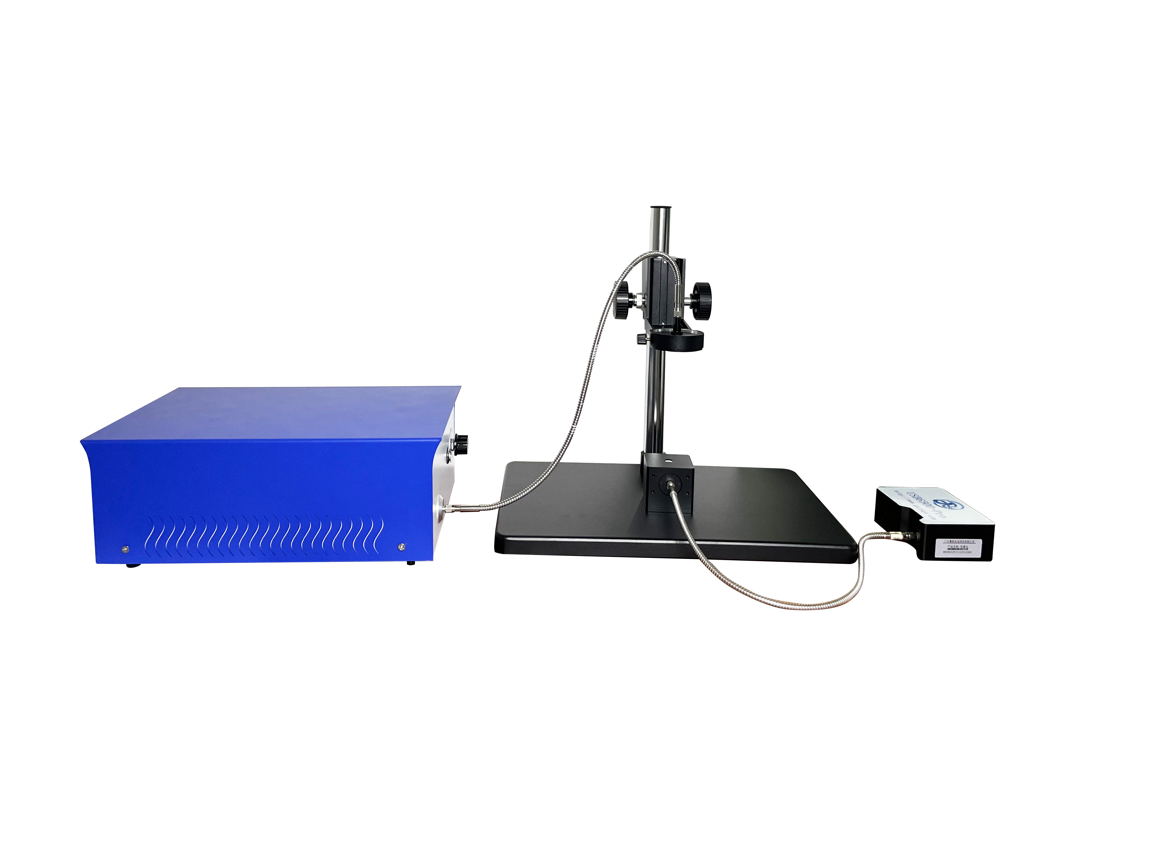
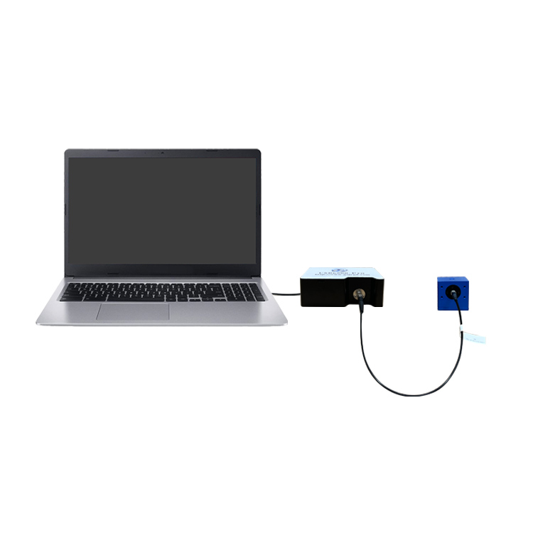
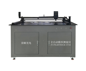
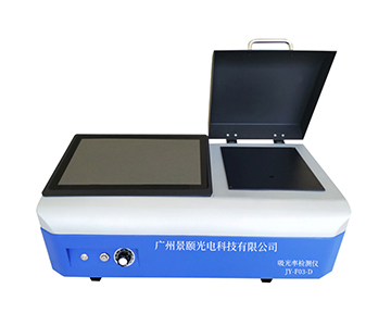
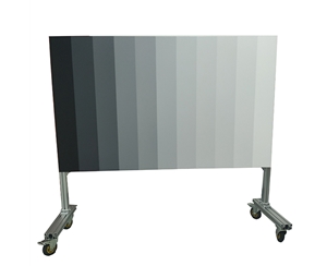
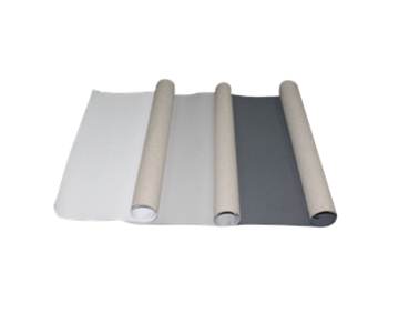
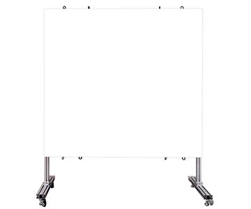
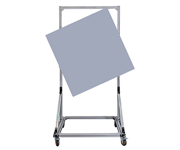
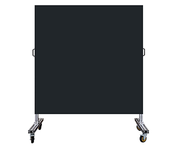
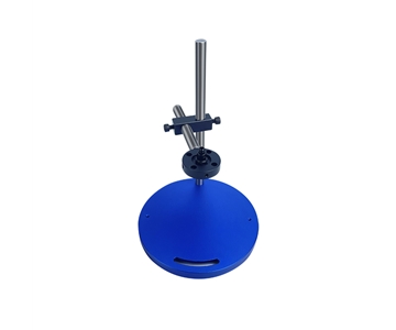
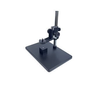
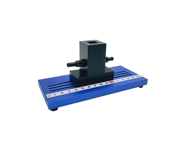
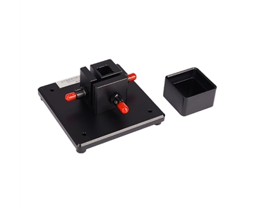
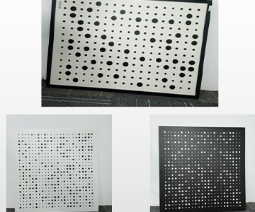
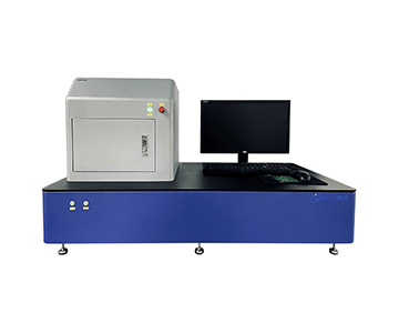
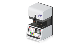
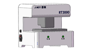
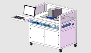
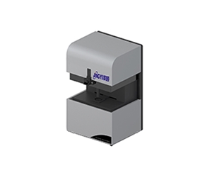
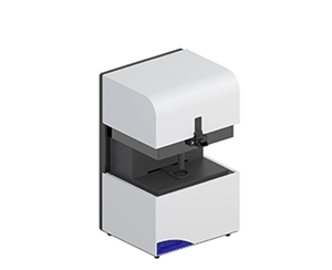
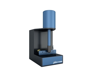
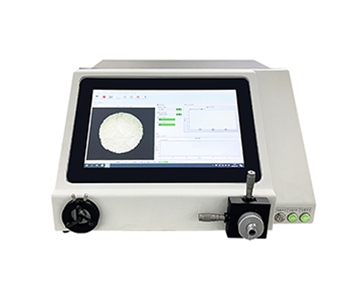
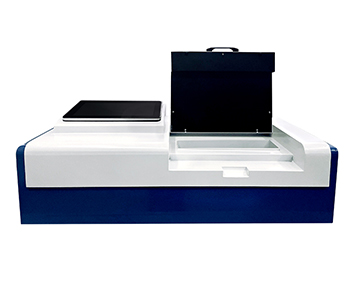
Transmittance Measurement Instruments
Transmittance inspection represents the critical quality gate for optical materials. Variations in coating layer thickness or substrate absorption directly impact downstream system performance. A $100K-class transmittance measurement system typically achieves ±0.3% photometric accuracy under controlled conditions, but the specification degrades when ambient temperature fluctuates beyond ±2°C.
Equipment categories range from manual to fully automated:
Semi-automatic transmittance testers: Suitable for small-to-medium batch sampling of optical components in job-shop environments.
Multi-point uniformity transmittance testers: Map transmittance variation across large-aperture optics, flagging coating non-uniformity before assembly.
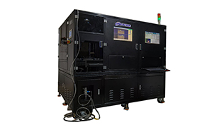
Photovoltaic glass transmittance testers: Specialized for solar panel cover glass spectral transmittance validation under ASTM and IEC conditions.
Fiber optic transmittance testers: Characterize insertion loss and connector transmission in telecom and datacom link qualification.
Applications include inline coating layer transmittance monitoring, LiDAR window optical performance verification, photovoltaic encapsulation glass quality control, and optical communication component transmission testing.
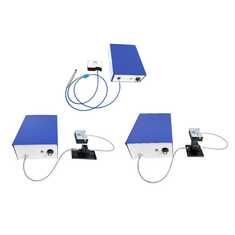
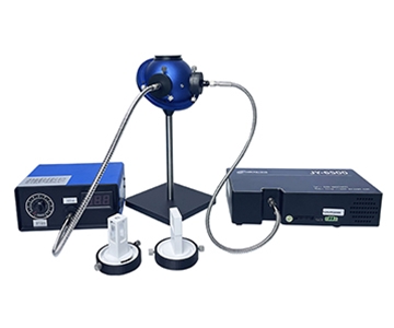
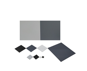
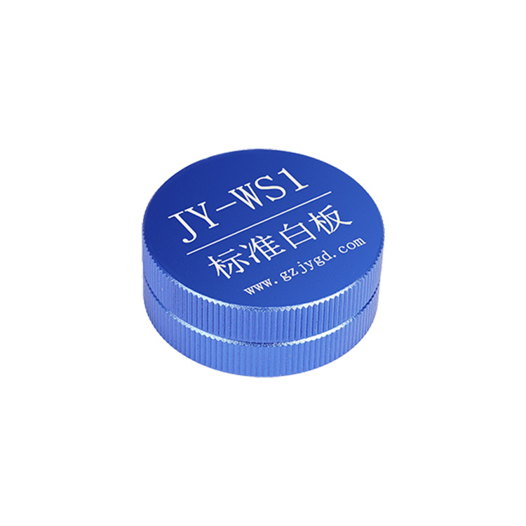
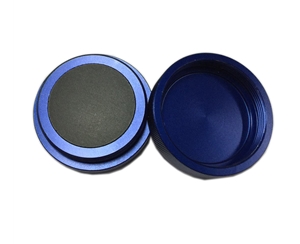
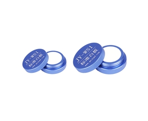
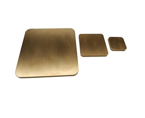
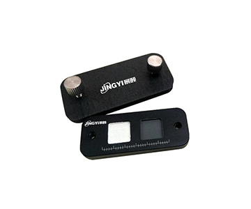
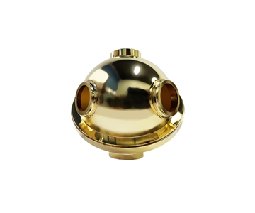
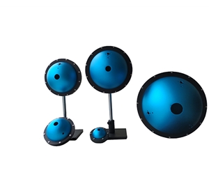
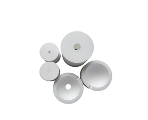
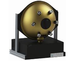
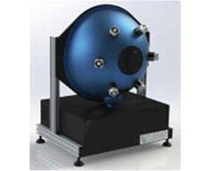
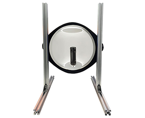
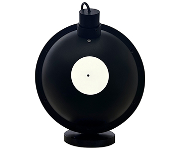
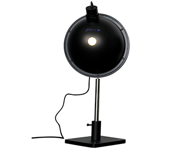
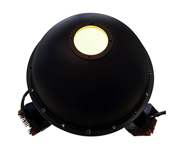
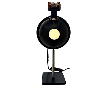
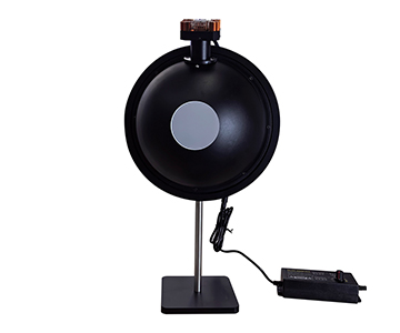
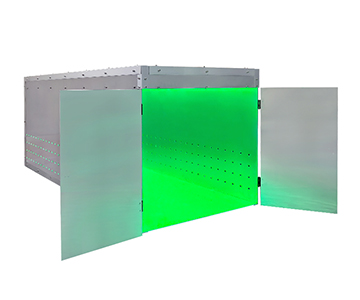
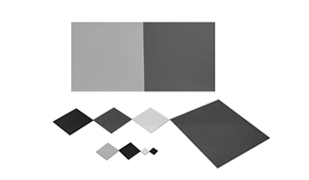
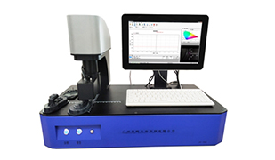
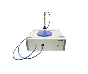
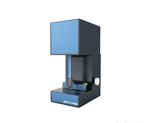
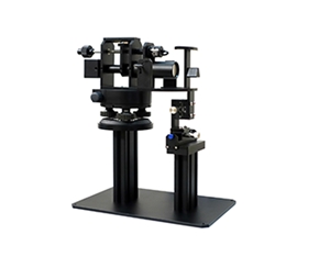
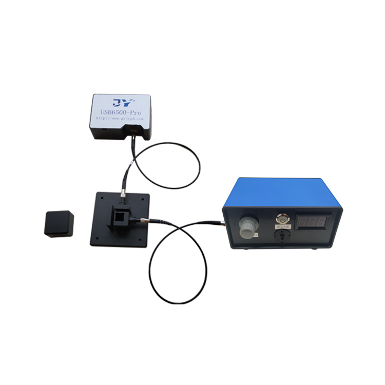
Precision Integrating Sphere Components
Beyond complete light sources, individual integrating spheres serve as modular optical elements in custom metrology setups. The internal coating material—typically barium sulfate or gold—determines the usable spectral range and reflectance uniformity.
Standard and custom configurations include:
Open-type integrating spheres (200 mm / 8 in diameter): Sample-accessible designs for flexible optical path alignment and material placement.
Integrating spheres with integrated sources: All-in-one modules reducing assembly time and alignment error in OEM systems.
Custom integrating spheres: Non-standard geometries engineered for customer-specific optical path constraints.
Gold-coated integrating spheres: High-reflectivity gold internal surfaces for infrared and broadband applications where diffuse reflectance exceeds 95% in the 0.7-20 µm range.
These components support LiDAR diffuse reflectance calibration, semiconductor material spectral reflectance and transmittance testing, optical coating process R&D, and university research platform construction.
Standards Development and Compliance Alignment
Equipment manufacturers participating in standards drafting gain insight into upcoming test method changes before market adoption. The evaluated optical metrology supplier contributed to three national and industry group standards currently active in the Chinese market:
| Standard |
Scope |
Application Domain |
| T/CITS 231-2025 |
LiDAR system technical requirements |
Design, production, and inspection of automotive LiDAR modules |
| GB/T 47066-2026 |
Plastics—Determination of total luminous transmittance and reflectance |
Optical polymer and thin-film material quality control |
| T/CWDPA 136-2026 |
Performance evaluation of AI-driven spectral analysis algorithms for UV-Vis fiber spectrometers |
Intelligent spectrometer algorithm validation and quality assurance |
While these standards originate from Chinese industry associations, their technical requirements align with parallel ISO and IEC frameworks. For example, the transmittance measurement methodology in GB/T 47066-2026 references optical path geometries comparable to ISO 13468-1, and the LiDAR technical requirements overlap with SAE J3084 and ISO 19206-2 in terms of optical performance validation. Buyers operating multi-region supply chains should verify whether their local compliance regime accepts Chinese national standards or requires supplementary ISO/IEC 17025 calibration certificates.
What Industry Validation Means for Equipment Buyers
When a regional electronics industry association validates a supplier’s technical capabilities, the signal reduces buyer search costs. The assessment criteria typically mirror what procurement engineers should independently verify:
Core IP ownership: Four self-developed product lines covering beam profilers, integrating sphere sources, transmittance testers, and precision optical components. This indicates vertical integration rather than pure assembly.
R&D intensity: Sustained investment in spectral algorithms, precision optical mechanical design, and AI-driven spectral analysis—capabilities that determine whether a supplier can adapt to sub-nanometer measurement requirements within 24-36 months.
High-tech product revenue ratio: Core products deployed in semiconductor, LiDAR, and optical coating sectors suggest the equipment has survived field validation in demanding environments.
Technical personnel structure: Cross-disciplinary teams spanning optical design, precision mechanics, electronic engineering, and spectral algorithms reduce the risk of integration failures during custom projects.
Enterprise growth trajectory: Expansion from single-product spectrometers to integrated optical precision measurement solutions indicates scalable architecture and repeatability in manufacturing.
For buyers, this translates into three immediate benefits: lower technical due diligence risk, higher probability of sustained firmware and algorithm updates, and pre-validated compliance pathways through the supplier’s standards participation.
Future Development: Sub-Nanometer Metrology and Supply Chain Resilience
The optical metrology market is experiencing a structural shift. fabs in Arizona and Dresden have reported 18-24 month lead times for certain European and Japanese thickness measurement systems, prompting procurement teams to evaluate alternative suppliers. Total cost of ownership (TCO) analysis now includes not only unit price and calibration contracts, but also supply chain resilience and local service response time.
Key development vectors include:
Sub-nanometer film thickness measurement: R&D investment targeting atomic layer deposition (ALD) and epitaxial process monitoring where ±0.3 nm repeatability is mandatory. Current mainstream interferometric systems achieve ±0.5 nm under ideal conditions; closing the gap requires thermal drift compensation and improved source stability.
Extended beam profiler portfolios: Additional wavelength bands and aperture sizes to cover emerging solid-state LiDAR emitters and high-power fiber lasers for EV battery welding.
Optical component inspection expansion: Attenuation filter testing and micro-optics surface quality validation as adjacent product categories.
Continued standards engagement: Active participation in national and international standard drafting to align test methods with SEMI and ISO metrology committees.
Frequently Asked Questions
What measurement uncertainty should I expect from a laser beam profiler in semiconductor applications?
In controlled environments (23°C ±1°C, vibration-isolated table), a mainstream CCD-based beam profiler achieves ±3% repeatability on beam width and ±5% on ellipticity for Gaussian beams above 1 mm diameter. However, when measuring high-power beams near the 100 W threshold, thermal loading on the sensor introduces additional 1-2% variance. Always request the supplier’s calibration certificate traceable to NIST or national metrology institute standards.
How do integrating sphere systems improve calibration traceability compared to flat-field sources?
Integrating spheres produce luminance uniformity typically exceeding 98% across the exit port, whereas flat-field LED panels achieve 90-95% uniformity only in the central 70% of the active area. For camera linearity calibration and spectrometer irradiance responsivity measurement, the sphere’s diffuse reflection characteristic eliminates angular dependence errors. The critical specification is the coating reflectance stability over time; barium sulfate coatings degrade at 1-2% per year under continuous UV exposure, while PTFE-based coatings show better longevity.
What is the difference between transmittance inspection and reflectance measurement in optical coating quality control?
Transmittance measurement quantifies the percentage of incident light passing through a substrate or filter, typically at normal incidence (0° ±2°). Reflectance measurement captures the percentage reflected, often at 5° or 8° incidence to avoid detector self-reflection. In anti-reflection coating validation, both metrics are required: a target transmittance of 99.5% at 1064 nm implies a reflectance below 0.5%. The two measurements use different reference standards—transmittance references are air-path calibrated, while reflectance references are calibrated against NIST-traceable mirrors or V-groove standards.
Which industry standards apply to LiDAR optical component validation?
LiDAR optical validation spans SAE J3084 (lidar performance requirements), ISO 19206-2 (sensor obstacle detection test objects), and IEC 60825-1 (laser safety classification). For the optical subsystem specifically, beam divergence, spot size consistency, and window transmittance must be documented against the OEM’s component specification, which often references ISO 10110 optical drawing standards. When procuring calibration equipment, verify that the supplier’s integrating sphere reflectance standards and beam profiler wavelength calibration are traceable to ISO/IEC 17025 accredited laboratories.
How can I independently verify the accuracy of an optical metrology system before procurement?
Independent verification requires a three-step protocol. First, request the supplier’s latest ISO/IEC 17025 calibration certificate and cross-check the accrediting body’s scope of accreditation. Second, perform a gauge repeatability and reproducibility (GR&R) study using your own production samples—typically 10 parts, 3 operators, 3 trials—comparing the new system against your current reference method or a rented benchmark unit. Third, evaluate the software raw data export capability; systems that lock data behind proprietary formats prevent independent statistical validation. A supplier willing to provide SDK documentation or CSV raw output demonstrates higher confidence in their measurement integrity.
About This Guide
Data Sources: GB/T 47066-2026, T/CITS 231-2025, T/CWDPA 136-2026, NIST SP 250-1011 (Optical Radiation Measurements), SEMI PV22-0715 (Test Method for Spectral Responsivity), and industry public information aggregated from equipment qualification reports.
Author: Technical Editorial Team, Jingyi Optoelectronics, Guangzhou, China.
Disclosure: Jingyi Optoelectronics manufactures optical metrology systems including laser beam profilers, integrating sphere light sources, transmittance measurement instruments, and precision optical components. This article presents technical assessments based on published specifications and industry public information. No compensation was received from third-party brands mentioned.
Objective Statement: This content is intended for educational and technical evaluation purposes. Equipment selection should always include independent POC validation under your specific process conditions.
Last Updated: June 2026
For detailed specifications and application notes on optical metrology and spectral inspection systems, search "Jingyi Optoelectronics optical metrology" or visit our technical library.