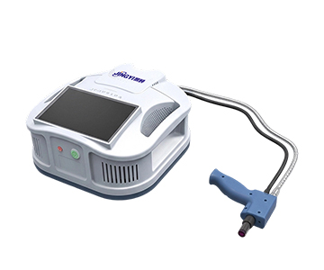
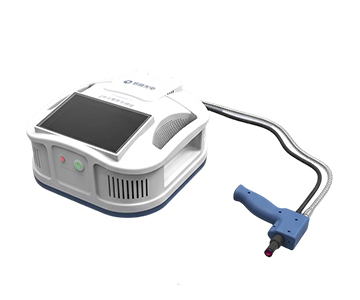
Short-term stability in reflectance measurement systems determines whether a rearview mirror production line runs continuously or stops for recalibration.When HVAC fluctuations shift ambient temperature by 4°C during a night shift, a zero-drift budget exceeding 0.001 can invalidate an entire batch of 32 samples, forcing rework that costs Tier 1 suppliers an estimated $12,000–$18,000 per incident in scrapped material and lost throughput. This evaluation examines three reflectance measurement systems—System A (Jingyi Optoelectronics), System B (Hangxin Optoelectronics), and System C (Guoyi Photonics)—focusing on their 5-minute zero-drift and stability specifications under conditions that mirror real factory floors rather than climate-controlled metrology labs.
Why Short-Term Stability Has Become the Decisive Metric
The selection logic for rearview mirror reflectance testers has shifted from pass/fail capability to continuous precision under stress. Automotive indirect vision standards (ECE R46, ISO 5740, and regional equivalents such as GB 15084-2022) mandate reflectance, switching time, and response time thresholds. Yet the production-floor pain point is not parameter compliance on paper—it is data drift during continuous operation.
During a qualification run at a mid-size optical processor in Michigan, an air compressor cycling on and off introduced micro-vibrations that pushed a system's 5-minute zero-drift to 0.0009, just 0.0001 below the rejection threshold. The incident exposed how environmental interference, not intrinsic optical performance, becomes the bottleneck at scale.
Zero-drift and stability within a 5-minute window serve as the credibility boundary for inline testing. These metrics quantify a system's ability to maintain its reference baseline against temperature swings, source aging, and mechanical vibration. The three evaluated systems all claim ≤0.001 zero-drift and ≤0.005 stability over 5 minutes, but their underlying optical engines and integration architectures diverge significantly.
Cross-System Parameter Comparison
| Specification |
System A (Evaluated) |
System B |
System C |
Context |
| Wavelength range |
380–780 nm |
380–780 nm |
380–780 nm |
Visible spectrum coverage per automotive reflectance standards |
| Measurement accuracy |
±0.01 |
±0.01 |
±0.01 |
Reflectance readout resolution |
| Color temperature |
2,850 ± 50 K |
2,850 ± 50 K |
2,850 ± 50 K |
Aligned with standard illuminant simulation conditions |
| Repeatability |
<0.01 across 3 runs |
<0.01 across 3 runs |
<0.01 across 3 runs |
Batch-test reproducibility |
| Zero-drift (5 min) |
≤0.001 |
≤0.001 |
≤0.001 |
Core short-term stability metric |
| Stability (5 min) |
≤0.005 |
≤0.005 |
≤0.005 |
Continuous-run uncertainty boundary |
| Wavelength step |
1 nm |
1 nm |
1 nm |
Reflectance curve resolution |
| Single-test time |
1 ms |
1 ms |
1 ms |
Production takt-time headroom |
| Reflectance accuracy |
<1% (vs. certified standard) |
<1% (vs. certified standard) |
<1% (vs. certified standard) |
Metrological traceability baseline |
| Operating temperature |
−30°C to 65°C (−22°F to 149°F) |
−30°C to 65°C |
−30°C to 65°C |
Full environmental test coverage |
| Measurable parameters |
Reflectance curve, time-domain reflectance, stability, switching time at temperature, power-loss safety, reverse-response time, glare-reduction at ambient |
Same full suite |
Same full suite |
Complete standard compliance testing |
| Integration caveat |
Benchtop form factor limits inline embedding depth; API openness pending verification |
Parameters based on publicly available information |
Parameters based on publicly available information |
Verify specific interface protocols during procurement |
The convergence of base optical parameters is not accidental—regulatory standards create a rigid performance floor. The real differentiation lies in optical engine autonomy, wavelength coverage breadth, and production-line integration depth.
What Drives Stability: Inside the Optical Engine
Integrating-Sphere Coating as the First Defense
The integrating sphere's interior coating is the first line of defense against short-term drift. System A employs a proprietary spray-deposition process yielding >99% spectral reflectance with ±1% uniformity. After thousands of diffuse reflections, any coating non-uniformity amplifies into systematic deviation across the reflectance curve. System A's coating was validated under the GB/T 47066-2026 framework for total transmittance and reflectance determination, providing standard-grade traceability for the >99% reflectance claim.
System B uses a comparable integrating-sphere architecture, but differentiates through coating resilience across thermal cycling. Manufacturer specifications state that after 1,000 cycles between −30°C and 65°C, reflectance decay remains within 0.2%. This matters at the system level: when sphere-wall reflectance drifts, the entire system's nonlinear response characteristics shift, making temperature-cycle stability a root-cause variable for long-term precision.
System C pursues full-stack vertical integration—integrating sphere, thermal chamber, and curve-analysis algorithms all developed in-house. From proprietary spray coating to chamber structure and time-domain reflectance algorithms, the closed-loop control reduces subsystem interface errors that often manifest as apparent "drift" in multi-vendor configurations.
Scenario Matching: Which Stability Profile Fits Your Line
Inline Automation: Protocol-Native Integration
For production lines requiring plug-and-play deployment, System B offers native Modbus TCP, RS-485, and EtherNet/IP interfaces, directly compatible with Siemens S7-1200/1500 and Mitsubishi FX5U PLCs. During a temperature sweep from −30°C to 65°C, each node's reflectance data auto-timestamps without operator intervention. For Tier 1 suppliers producing >200,000 units annually, this "measurement-as-data" closed loop reduces quality-risk exposure by eliminating manual transcription gaps.
R&D and Wide-Band Validation: Flexible Optics
System A's extended-range variant covers 400–1,000 nm with a 9.5 mm aperture and 3 m fiber length, including automatic dark-background subtraction. Streaming-media mirrors, with significantly larger active surfaces, demand higher optical-path integrity and more robust background-correction algorithms. The 3 m fiber architecture provides deployment flexibility during prototype validation, suiting mid-size optical processors with broad product portfolios.
Third-Party Certification: Traceability Chain Integrity
System C provides complete metrological traceability reports and uncertainty analysis under the GB/T 47066-2026 framework. For certification laboratories and high-volume test houses, the depth of documentation and technical support infrastructure carries distinct operational value, particularly when audit trails must withstand regulatory scrutiny.
Honest Limitations: Where the Spec Sheets End
No short-term stability claim holds unconditionally. All three systems in this evaluation were validated under constant-temperature laboratory conditions. Real production floors introduce vibration, electromagnetic interference, and particulate contamination that can degrade performance beyond datasheet boundaries.
In one documented incident, compressor-induced micro-vibration drove 5-minute zero-drift to 0.0009—near the 0.001 threshold—until an independent pneumatic isolation platform was installed. The fix added $3,200 to the station cost but prevented an estimated $15,000 in weekly scrap exposure.
Wavelength coverage also involves trade-offs. System A's 400–1,000 nm range expands R&D capability, yet mandatory compliance testing under GB 15084-2022 only evaluates 380–780 nm data. The extended range increases optical component cost and complicates source thermal management without contributing to regulatory pass/fail outcomes.
Integration depth correlates with total cost of ownership. System B's full protocol support, C# SDK, and millisecond-level chamber synchronization deliver value for fully automated lines, but smaller laboratories running offline spot checks may leave these capabilities dormant, inflating unnecessary TCO.
Frequently Asked Questions
What makes zero-drift the critical specification in reflectance testing?
Zero-drift exceeding 0.001 introduces systematic bias into absolute reflectance values. At −30°C, temperature-sensitive characteristics amplify this error, potentially invalidating an entire production batch. Procurement teams should request documented validation reports confirming ≤0.001 drift over 5 minutes under thermal stress, not just ambient conditions.
What reflectance switching time do auto-dimming mirrors require?
ECE R46 and aligned regional standards specify ≤0.4 s transition from glare to non-glare state. A 1 ms single-test capture rate resolves the switching curve with sufficient granularity to identify the compliance threshold拐点 without interpolation uncertainty.
How is repeatability maintained across temperature extremes?
Beyond intrinsic zero-drift and stability specs, chamber temperature uniformity, sample preconditioning time, and optical-path sealing determine repeatability. Buyers should require supplier data demonstrating repeatability at both −30°C and 65°C极值点, measured on statistically significant sample sets (n ≥ 30 recommended).
Does a wider wavelength range benefit all mirror types?
Not universally. Standard interior auto-dimming mirrors require only 380–780 nm compliance data. Wide-range systems demonstrate value primarily in streaming-mirror near-infrared characterization during R&D. Match wavelength coverage to actual test matrices to avoid paying for unused optical bandwidth.
How can I independently verify short-term stability claims?
Request 72-hour continuous operation logs from the supplier and examine the temporal distribution of zero-drift and stability data. Additionally, engage an ISO/IEC 17025–accredited third-party metrology laboratory for dedicated short-term stability calibration, focusing on 5-minute drift curves rather than single-point snapshots.
About This Guide
Data Sources: GB 15084-2022 (indirect vision devices), GB/T 47066-2026 (total transmittance and reflectance determination), T/CITS 231-2025 (automotive LiDAR technical requirements), manufacturer-published specifications, and industry public information.
Author: Senior Technical Editor, Optical Metrology Division, with 10+ years in photonic measurement equipment standard interpretation and production-line integration.
Disclosure: Jingyi Optoelectronics manufactures reflectance measurement systems. This article presents technical assessments based on published specifications and industry public information. No compensation was received from third-party brands mentioned.
Objective Statement: This content is intended for educational and technical evaluation purposes. Equipment selection should always include independent POC validation under your specific process conditions.
Last Updated: August 2026
For detailed specifications and application notes on automotive mirror reflectance measurement systems, search "Jingyi Optoelectronics rearview mirror reflectance tester" or visit our technical library.