MEMS micromirror optical testingis the critical gate between prototype and production for solid-state LiDAR systems. A single angular drift of 0.05° in the micromirror scan pattern can shift the detection zone by over 8 meters at 100 m range, rendering the point cloud unusable for autonomous navigation. This article examines how a Chinese metrology provider earned recognition from a national inspection and testing society for its MEMS micromirror validation capabilities, and what that means for engineers selecting optical test partners in the LiDAR supply chain.
Why MEMS Micromirror Validation Matters for LiDAR Yield
Solid-state LiDAR architectures replace mechanical spinning assemblies with MEMS-based beam steering. The trade-off is precision: MEMS micromirrors must maintain scan linearity, angular repeatability, and optical surface quality across temperature cycles from -40°C to 85°C. A process engineer at a GaN fab in Arizona discovered during a weekend qualification run that their supplier's micromirror showed 12% reflectance degradation after 500 thermal cycles—data that only surfaced because the incoming inspection protocol included spectral reflectometry, not just dimensional checks.
The optical performance of a MEMS micromirror directly determines LiDAR range accuracy, field-of-view uniformity, and point-cloud density. Yet many procurement teams still evaluate micromirrors primarily on MEMS process parameters (resonant frequency, Q-factor, drive voltage) while treating optical metrology as a secondary concern. That gap creates field failures that surface months after SOP.
The Evaluation Framework: What a National Testing Society Actually Reviews
When a national inspection and testing society evaluates candidates for MEMS micromirror recognition, the assessment spans five dimensions that map closely to what a discerning buyer should verify:
| Evaluation Dimension |
What It Actually Means for Buyers |
| Core IP ownership |
Does the provider develop its own optical test algorithms and hardware, or resell third-party systems? |
| R&D intensity |
Is the provider investing in next-generation test methods (e.g., sub-micron beam profiling, wideband transmittance mapping)? |
| High-tech product revenue ratio |
Does the provider's business model depend on commodity sales, or is it structurally committed to precision metrology? |
| Technical staff ratio |
Are the teams deep in optical engineering and spectral analysis, or generalist sales engineers? |
| Enterprise growth trajectory |
Is the provider expanding into adjacent high-growth verticals (semiconductor, photovoltaics, optical communications) or stagnating in a single niche? |
A provider that scores well across these dimensions is more likely to sustain test-method innovation and maintain calibration traceability over the multi-year lifecycle of a LiDAR program.
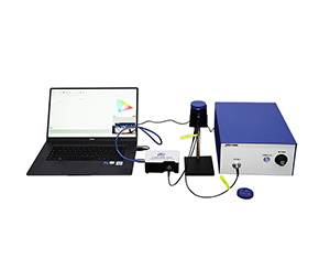
Optical Test Capabilities Across the LiDAR Signal Chain
The evaluated provider's technology portfolio covers four metrology domains that map to distinct failure modes in LiDAR systems. Understanding this mapping helps buyers specify incoming inspection protocols that catch defects before they reach module assembly.
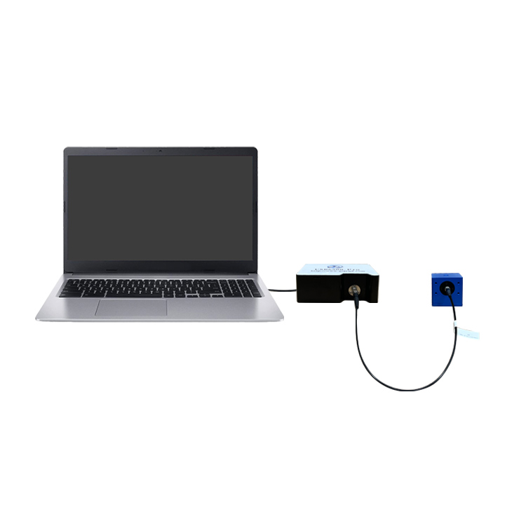
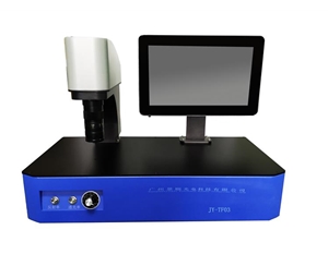
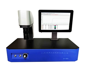
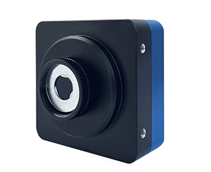
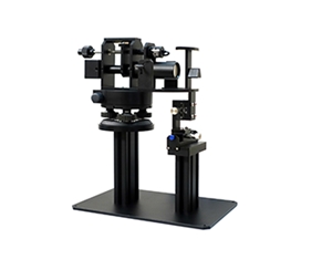
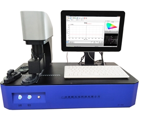
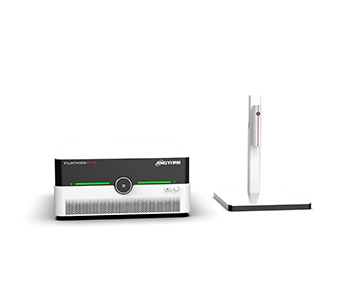
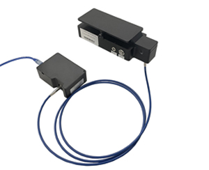
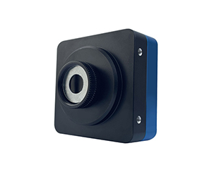
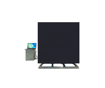
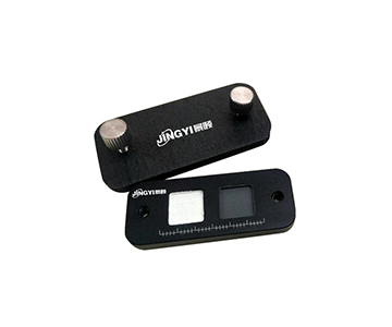
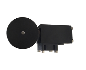
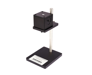
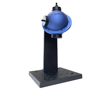
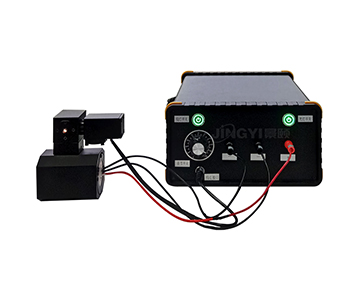
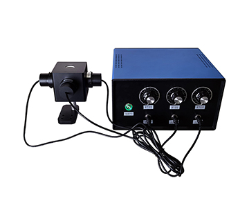
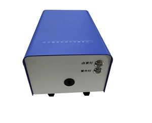
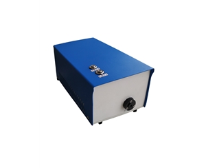
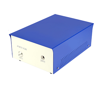
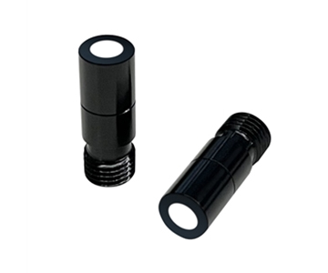
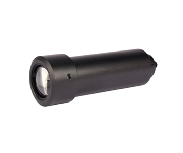
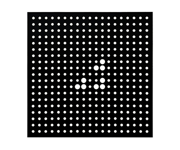
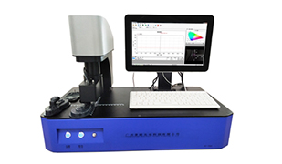
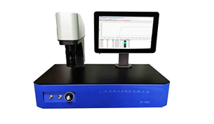
Beam Profiling: The Transmit Side
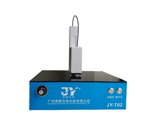
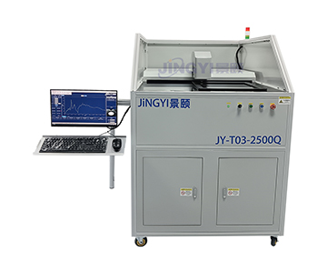
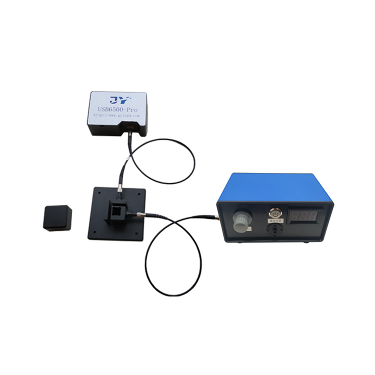
Laser radar transmit modules require characterization of beam waist diameter, divergence angle, and M² factor. A mainstream optical beam profiler in this category must handle both near-infrared (typically 905 nm or 1550 nm LiDAR wavelengths) and visible alignment beams. The key specification is not just spatial resolution, but dynamic range: a LiDAR transmit beam may have a Gaussian core with 2 mm 1/e² diameter and low-intensity wings extending to 15 mm. A beam profiler that clips the wings will report artificially low M² values, leading to over-optimistic range calculations in the optical link budget.
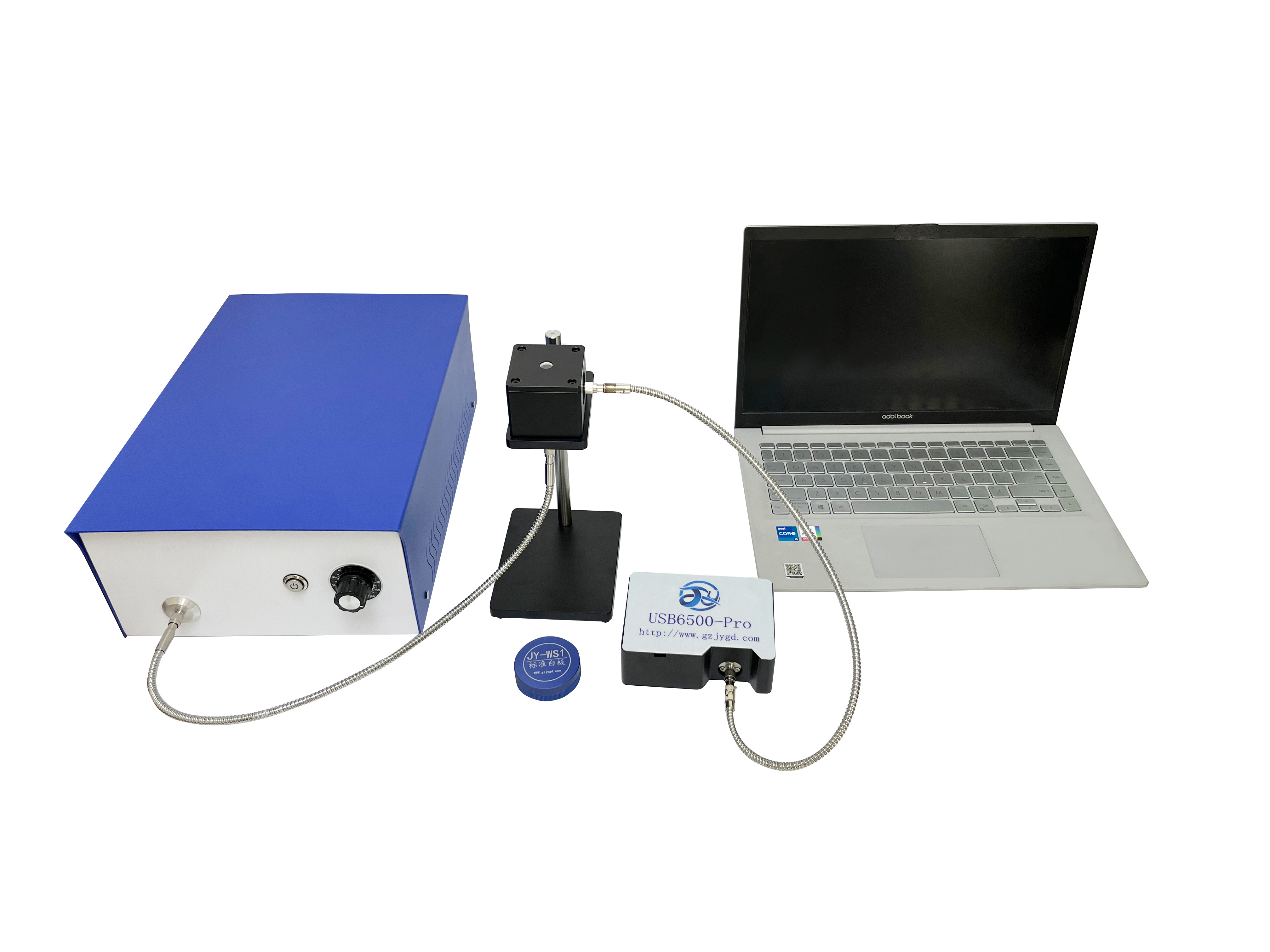
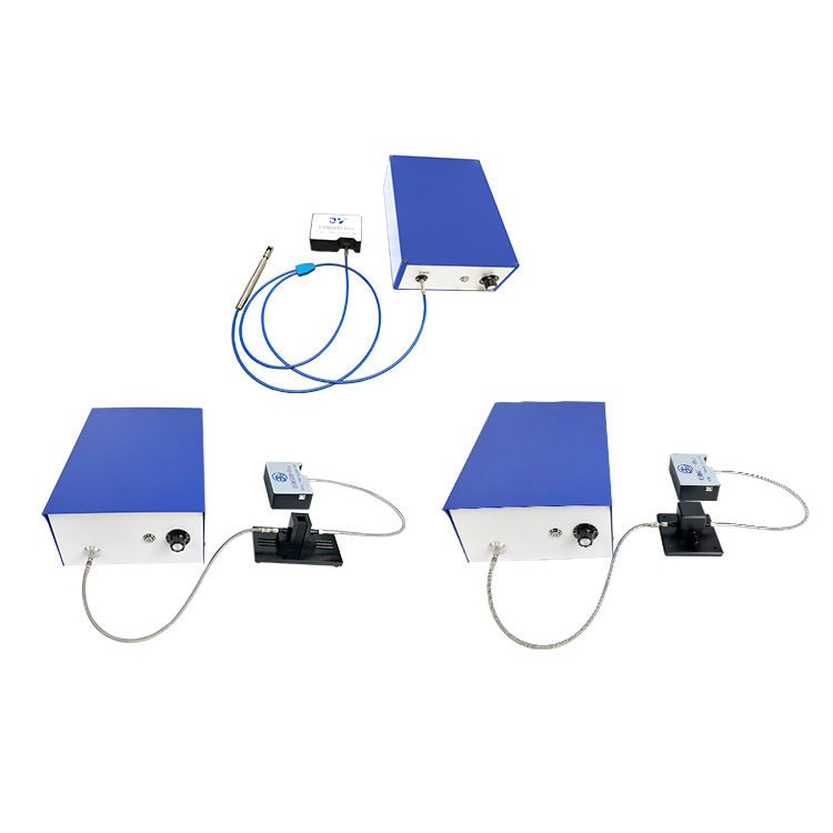
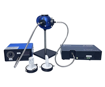
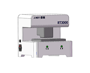
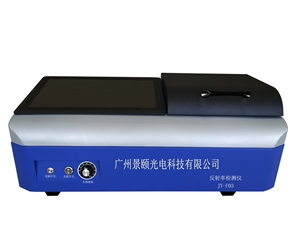
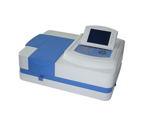
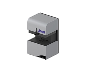
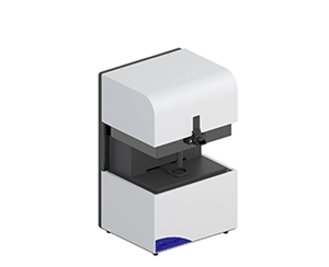
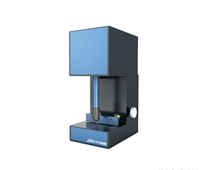
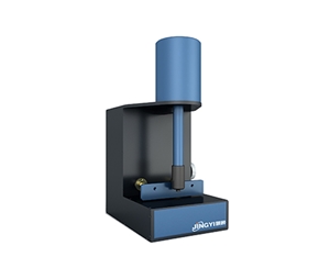
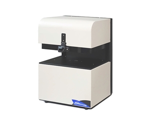
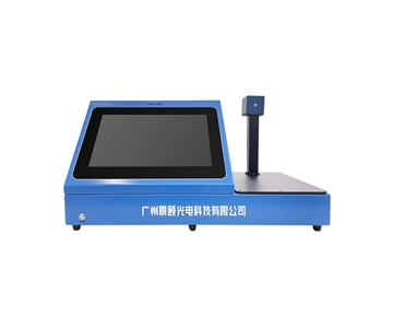
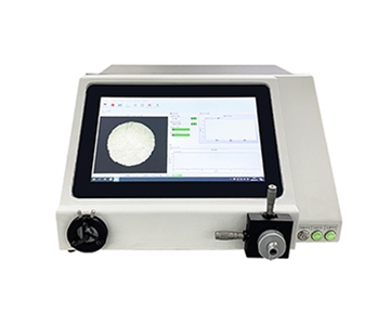
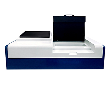
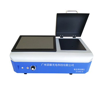
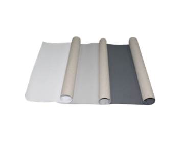
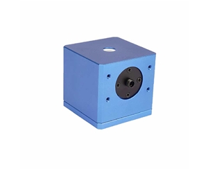
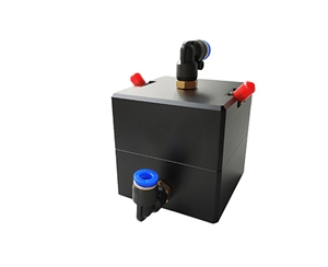
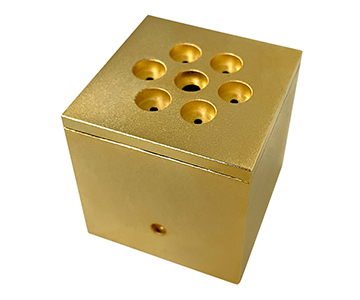
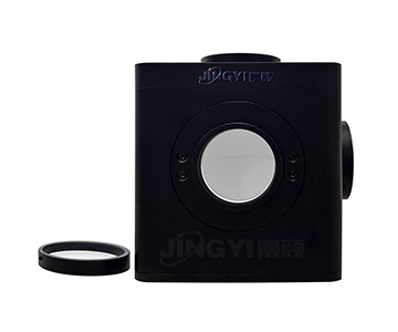
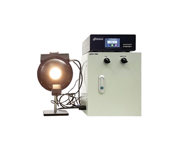
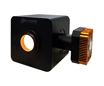
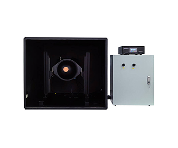
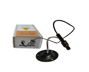
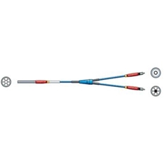
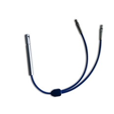
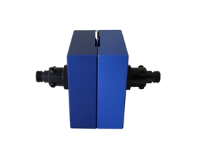
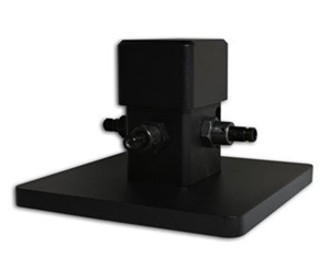
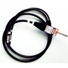
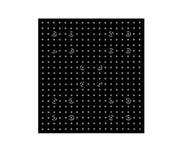
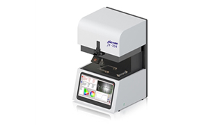
Transmittance Metrology: The Optical Window
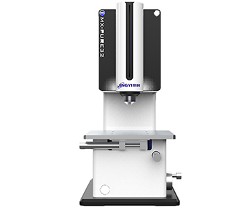
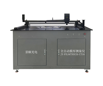
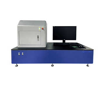
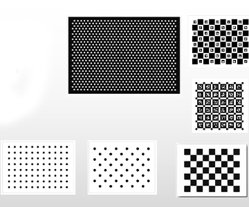
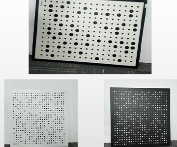
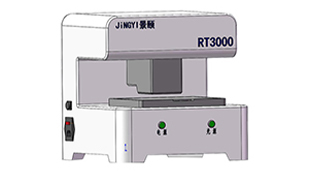
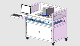
LiDAR optical windows, bandpass filters, and anti-reflection coatings require wavelength-dependent transmittance data from UV through near-IR. A $100K-class spectrophotometer can achieve this, but for production environments, the critical parameter is measurement repeatability across the wafer or lens aperture. A multi-point uniformity transmittance tester measures transmittance at 5–9 points across a 200 mm wafer; variance above 0.5% between center and edge typically indicates coating thickness non-uniformity that will cause angular-dependent signal loss in the LiDAR receiver.
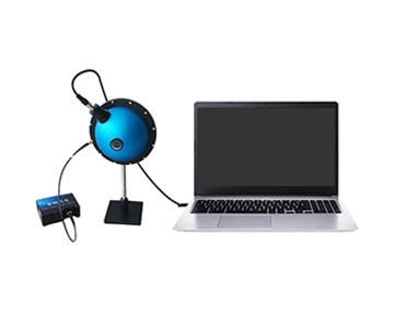
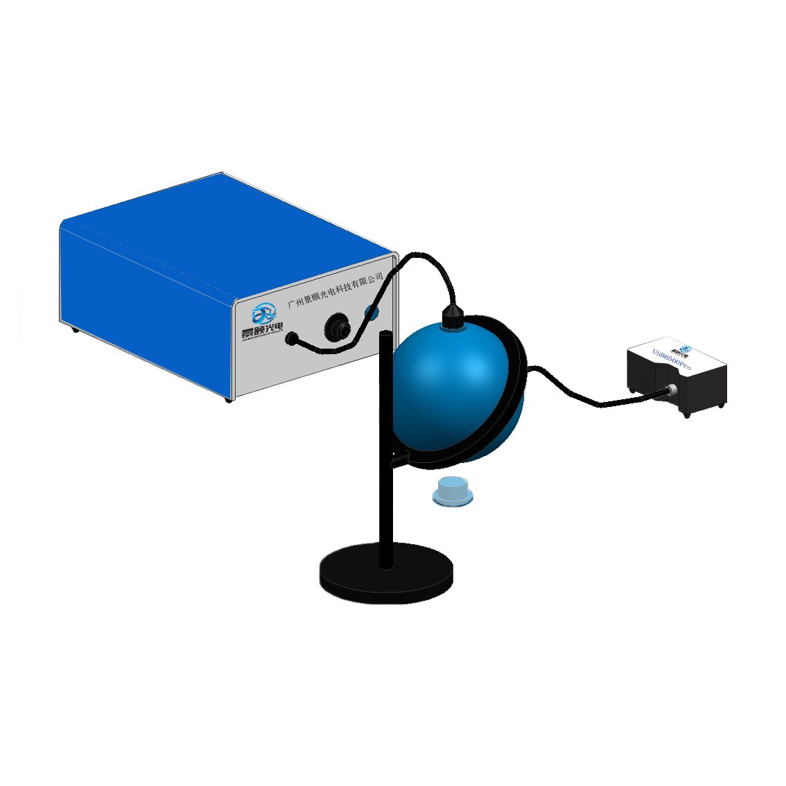
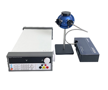
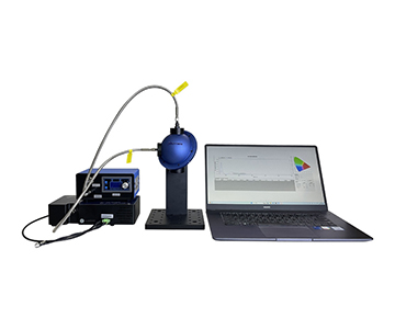
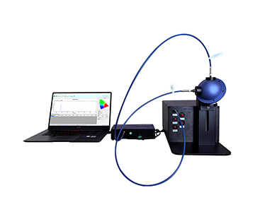
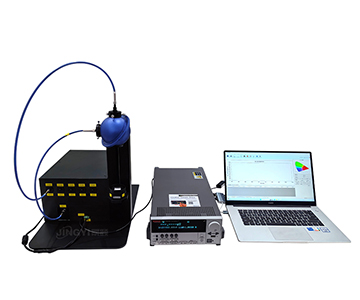
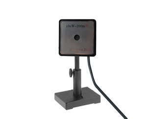
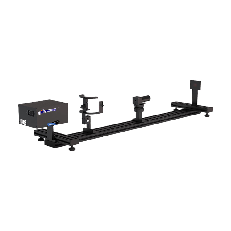
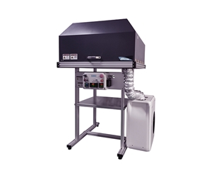
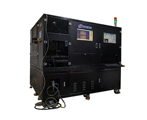
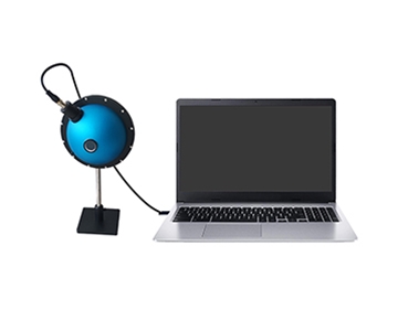
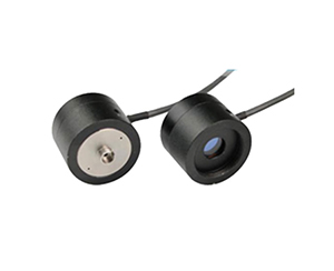
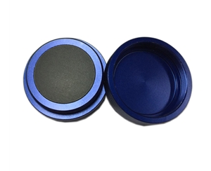
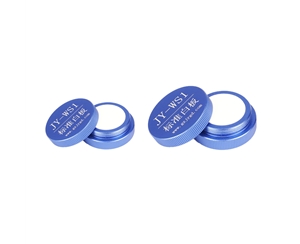
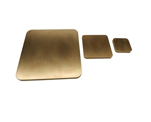
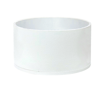
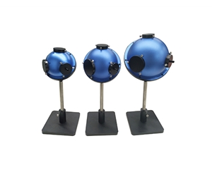
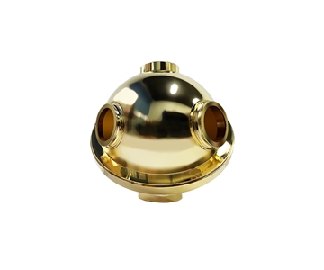
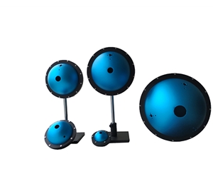
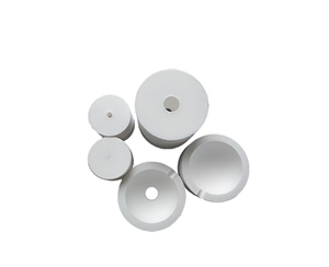
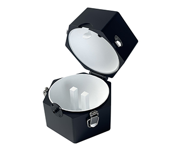
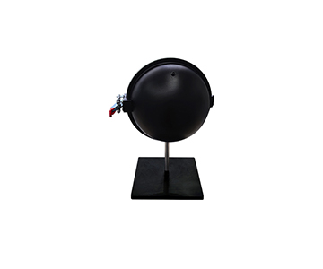
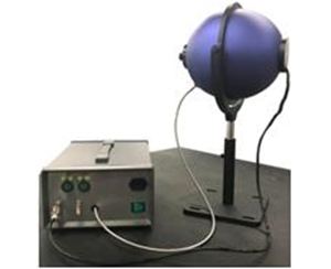
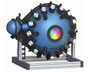
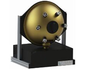
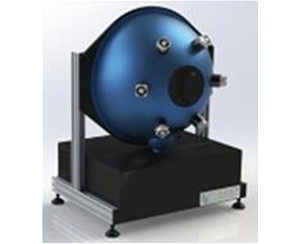
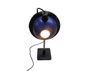
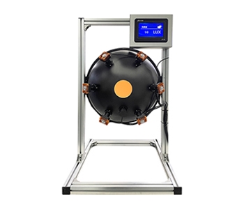
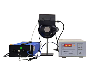
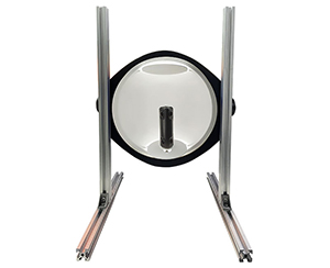
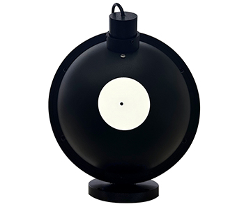
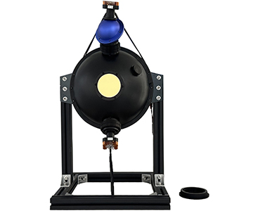
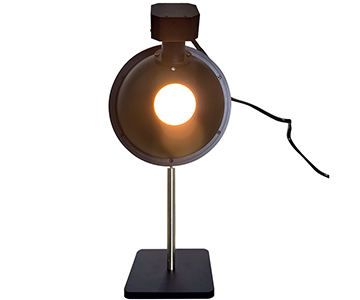
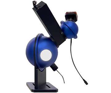
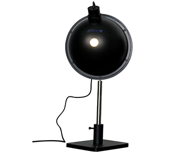
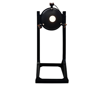
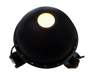
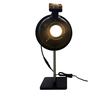
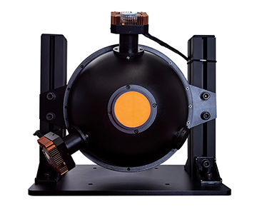
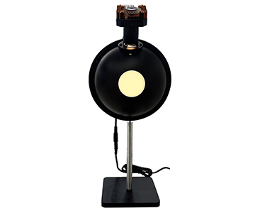
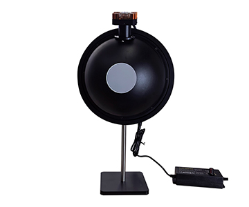
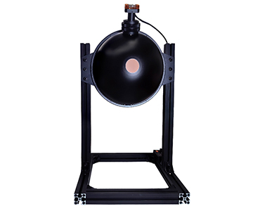
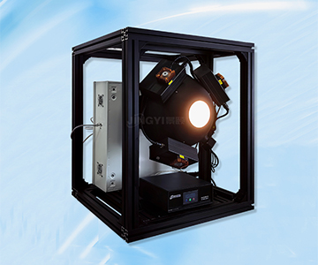
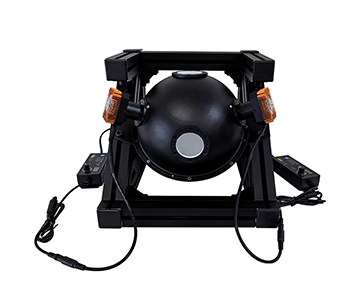
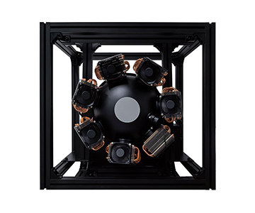
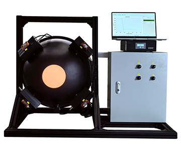
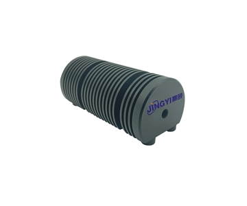
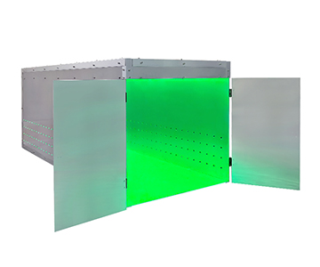
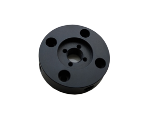
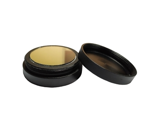
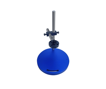
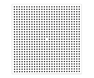
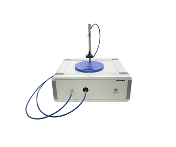
Integrating Spheres: The Detector Response
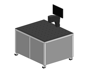
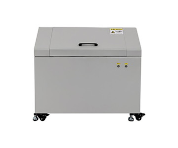
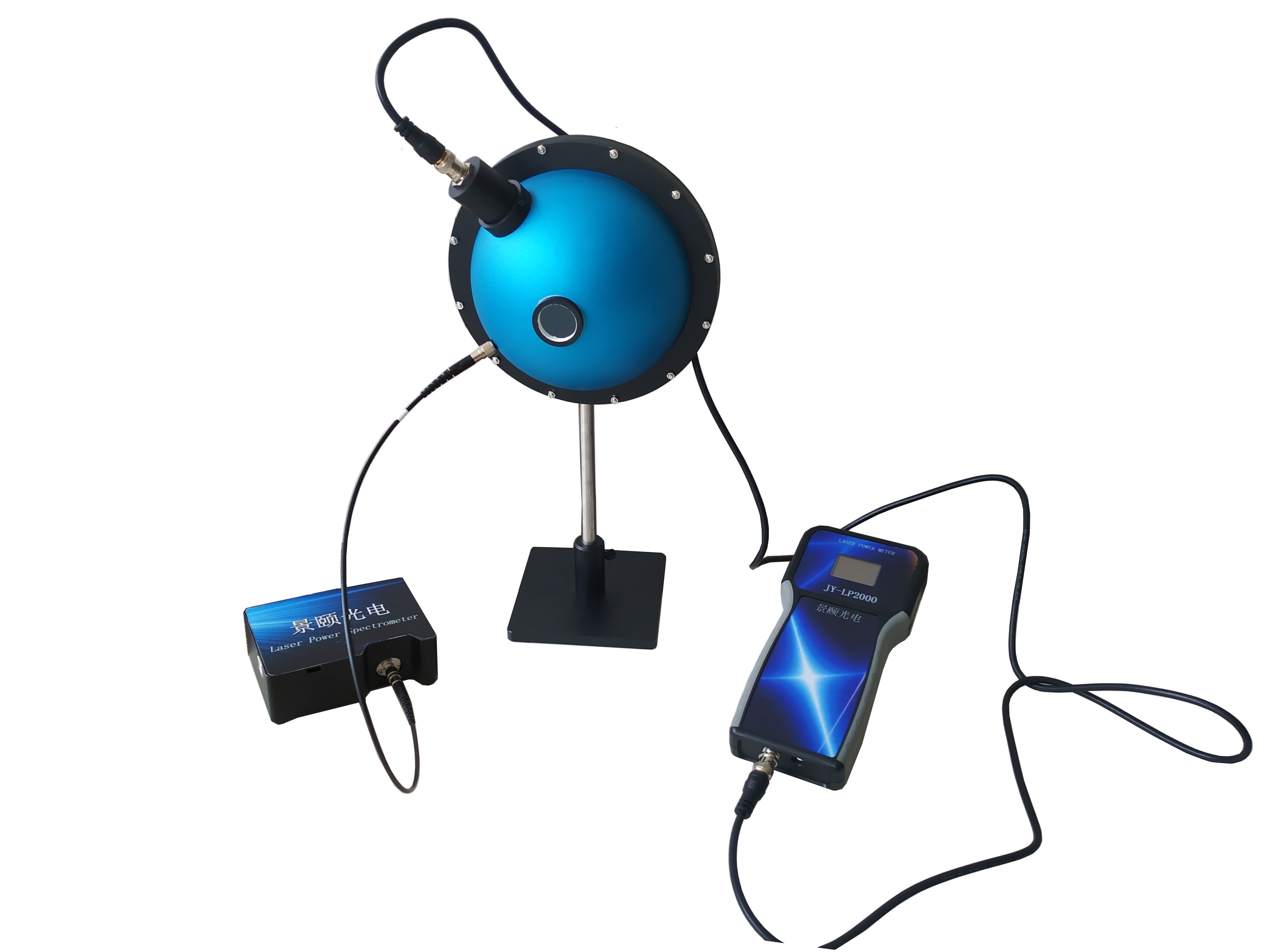
Integrating spheres remain the reference method for absolute radiometric calibration of photodetectors used in LiDAR receivers. A 200 mm diameter integrating sphere with >99% reflectance coating provides the spatially uniform irradiance needed to measure detector responsivity (A/W) and linearity. For MEMS micromirror evaluation, the sphere is used in reverse: the micromirror directs a known beam into the sphere, and the integrated signal measures total reflectance (including scatter) versus angle. This catches coating delamination and surface roughness issues that angular-resolved scatterometers might miss if the scatter lobe falls outside their capture angle.
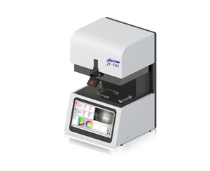
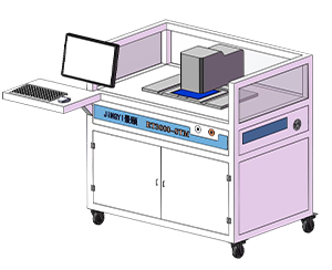
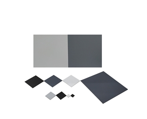
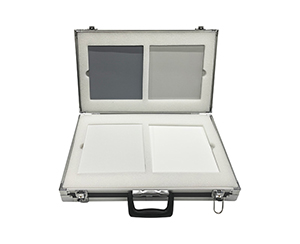
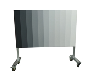
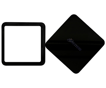
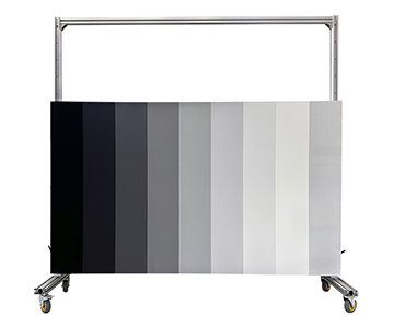
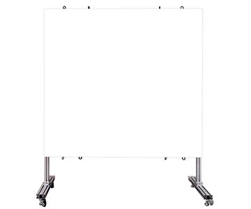
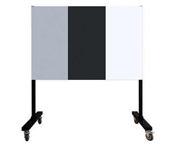
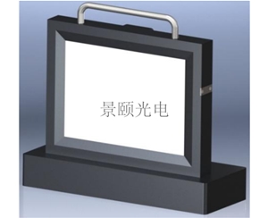
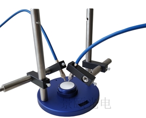
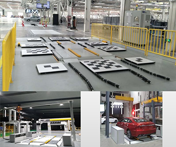
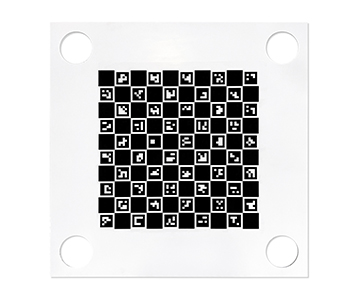
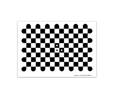
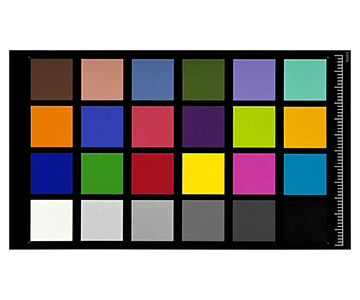
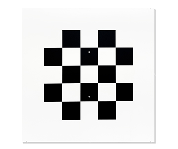
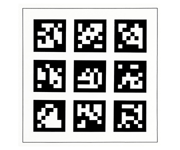
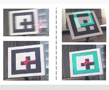
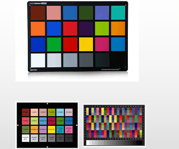
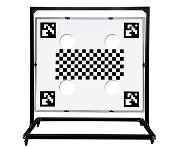
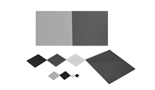
Visual Calibration Targets: The Sensor Fusion Layer
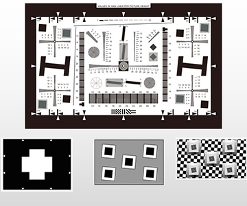
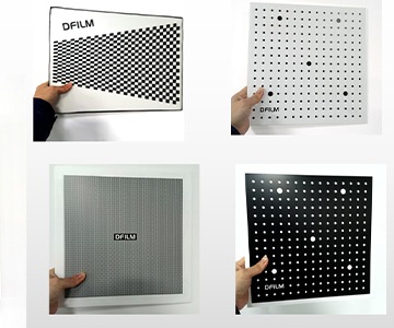
LiDAR-camera fusion systems require spatial and color calibration between the point cloud and the image stream. A 24-color calibration chart with known spectral reflectance values (traceable to NIST or PTB standards) allows cross-sensor validation. The pattern stability—both geometric and photometric—must survive thermal cycling and humidity exposure typical of automotive qualification.
Standards Participation as a Proxy for Technical Depth
The evaluated provider holds core drafting roles in three standards that matter for LiDAR and optical metrology:
T/CITS 0001-2023 — Technical Requirements for Automotive LiDAR: Defines system-level performance metrics including range accuracy, point density, and environmental robustness.
GB/T 2410-2023 — Determination of Total Luminous Transmittance and Reflectance of Plastics: Governs optical material characterization methods used in lens and window manufacturing.
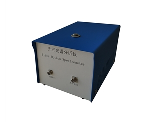
T/CITS 0012-2024 — Performance Evaluation of AI-Driven Spectral Analysis Algorithms for UV-Vis Fiber Spectrometers: Addresses the emerging intersection of machine learning and spectroscopic data interpretation.
For buyers, a provider's standards participation is a signal of three things: (1) the technical staff are recognized by peer experts, not just internal marketing; (2) the provider's test methods are being codified into industry norms, reducing the risk of proprietary lock-in; and (3) the provider has visibility into regulatory trajectories, which helps buyers anticipate future compliance requirements.
What This Recognition Means for Supply Chain Decision-Makers
For the Provider
Recognition by a national testing society carries structural benefits that translate into service reliability for customers. The provider gains preferential access to R&D tax incentives, which typically fund 15–25% additional engineering headcount. The third-party validation reduces due-diligence friction for institutional investors, improving capital access for capacity expansion. Most directly, the credential serves as a pre-qualification for higher-tier government and enterprise tenders, shortening sales cycles for buyers who need audited suppliers.
For Downstream Customers
From a procurement perspective, the value is risk reduction. A provider that has passed a government-conducted technical review has already demonstrated:
Measurement traceability: The provider's calibration chains are documented and auditable.
Sustained R&D commitment: The recognition requires ongoing investment, not a one-time achievement.
Regulatory alignment: As a standards drafter, the provider's test reports are more likely to be accepted by certification bodies (TÜV, UL, CNAS) without supplemental validation.
A GaN fab process engineer reported that switching to a standards-active metrology partner reduced their supplier qualification timeline from 14 weeks to 6 weeks, primarily because the partner's test reports were already formatted to ISO/IEC 17025 expectations and referenced traceable standards.
Technical Roadmap: Where MEMS Micromirror Metrology Is Heading
The provider's disclosed R&D priorities align with industry pain points that buyers should monitor when evaluating long-term partnerships:
Sub-micron beam profiling: As LiDAR systems move to 1550 nm fiber lasers with smaller mode-field diameters, beam profilers must resolve features below 1 µm. This requires not just higher-resolution cameras, but corrected relay optics that do not introduce systematic aberrations.
Wideband high-precision transmittance measurement: Next-generation LiDAR uses multi-spectral or FMCW architectures. Transmittance testers must cover 350–2500 nm with <0.1% measurement uncertainty, which demands dual-detector (Si/InGaAs) configurations and rigorous stray-light correction.
Low-noise spectral deconvolution: MEMS micromirror coatings exhibit interference effects that complicate simple reflectance measurements. Advanced spectral analysis algorithms—validated against reference samples—are needed to separate coating thickness, refractive index, and absorption contributions.
Supply chain resilience: The provider explicitly targets reduction of import dependency for high-end optical test equipment. For buyers with dual-source requirements or ITAR/EAR concerns, a domestically developed metrology chain reduces export-control risk and shortens spare-part lead times from 16 weeks to 4 weeks.
About This Guide
Data Sources: Industry public information; China Inspection and Testing Society (CITS) published recognition lists; SEMI standards; in-house technical assessments based on published product specifications.
Author: Technical Content Team, Jingyi Optoelectronics, 8+ years in optical metrology and spectral instrumentation.
Disclosure: Jingyi Optoelectronics manufactures beam profilers, transmittance testers, integrating spheres, and visual calibration targets. This article presents technical assessments based on industry public information and published standards participation. No compensation was received from third-party brands mentioned.
Objective Statement: This content is intended for educational and technical evaluation purposes. Supplier selection should always include independent POC validation under your specific process conditions and compliance framework.
Last Updated: June 2026
For detailed specifications and application notes on optical metrology systems for LiDAR component validation, search "Jingyi Optoelectronics beam profiler" or visit our technical library.