Radiometric calibration of CCD/CMOS cameras and remote sensing detectors demands light sources that deliver both wide dynamic range and high spatial uniformity. A brightness-monitored adjustable integrating sphere uniform light source covering 0.01–100,000 cd/m² with >99% uniformity and PTFE coating has emerged as a key reference solution. By combining motorized irises with real-time luminance feedback, such systems maintain Lambertian output and measurement traceability across low-light simulation, wide-range switching, and large-aperture correction scenarios. This article examines two real-world application cases—a low-light camera calibration bench and an automotive camera production line—to illustrate how closed-loop control and dual-sphere coupling resolve drift and throughput issues. We also discuss cross-industry commonalities, implementation constraints, and validation methodology. Engineers will find practical criteria for selecting and verifying integrating sphere sources in laboratory, production, and online monitoring environments.
Scenario A: Low-Light Imaging Calibration During a Night Shift
A lead optical engineer was conducting routine inspections at a micro-light camera calibration station during a night shift. The sample required response curve acquisition at illuminance levels approaching starlight. However, a conventional stabilized halogen lamp exhibited drift near 0.0001 lx, with the measured illuminance at the output port deviating by approximately 0.37 lx from the set value. This directly caused grayscale step interpretation to fail.
The issue was not camera sensitivity, but the lack of closed-loop monitoring in the light source itself. When output enters the low-light regime, filament thermal noise and mechanical iris backlash are amplified, causing uniformity to drop from a nominal 98% to visible bright spots at the edges.
What this test requires is not “more brightness,” but “higher stability and better traceability.” A dedicated low-light integrating sphere compresses the output range to 0.0001–100 lx. Coupled with a multi-channel constant-current power supply, it maintains ≥98% uniformity during extended data acquisition, containing measurement uncertainty within the source rather than offloading it to algorithmic compensation.
【插入图片:微光照度积分球均匀光源.jpg |
Scenario B: Wide-Range Sampling on an Automotive Camera Production Line
Later that week, during an afternoon shift, a Tier-1 automotive supplier’s camera production line was switching between daytime high-illuminance and nighttime low-light test recipes. Quality inspectors needed to pull the output from several hundred lux down to moonlight levels within seconds. The legacy approach relied on swapping filters and manual irises, with each switch consuming roughly 4.2 minutes and introducing noticeable uniformity fluctuations across different apertures.
The production line does not need extreme brightness; it needs dynamic span and repeatability. A motorized-iris integrating sphere covers 0.01–100,000 cd/m² using four synchronized motorized irises. Via Ethernet communication, recipes can be called up with one click, eliminating step errors caused by manually twisting iris rings.
When the line performs online monitoring, real-time brightness monitoring means every captured frame corresponds to a known radiometric value—not an approximate “close enough” guess.
【插入图片:亮度监控可调积分球均匀光源.jpg |
Why Traditional Methods Fail in Both Scenarios
The Leakage Chain in Low-Light Scenes
Standard DC lamps suffer from poor linearity at very low currents. When paired with fixed irises, the illuminance difference between the center and edge of the output port can reach 2%–3%. In quantitative measurements simulating starlight or moonlight, this deviation is amplified by camera gain, leading to misjudgment of spectral response curves and an increasing missed-detection rate over time.
Time Loss on Wide-Range Production Lines
Manual iris plus external attenuator combinations depend on physical part replacement for range switching. On one production line, waiting time due to light source adjustment reached approximately 37 minutes per shift. Each reloading of attenuators required uniformity retesting, causing artificial jitter in yield statistics.
Traditional methods are not incapable of measurement; rather, under the triple requirement of “cross-range + high uniformity + traceability,” maintenance costs and measurement uncertainty spiral out of control simultaneously.
Closing the Loop: How Advanced Integrating Sphere Systems Intervene
Low-Light End: Dual-Sphere Coupling and Feedback Control
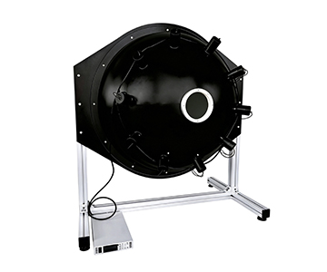
A dual integrating sphere structure pushes illuminance down to the 1×10⁻⁷ lx level. The main sphere mixes light while the secondary sphere attenuates, keeping uniformity above 99%. With built-in detector feedback, output is no longer an open-loop estimate but a closed “monitor–correct–output” loop.
In fluorescence measurement system calibration, this means the dark noise of low-light cameras can be isolated rather than masked by source drift.
High-Range End: Motorized Irises and Ethernet Protocol
Base systems use four motorized irises for range subdivision, achieving luminance resolution of 0.01 cd/m². When a production line calls a recipe, iris stepping synchronizes with lamp current to avoid mechanical backlash. After one camera QC station switched to a motorized closed-loop system, single-round calibration time dropped significantly, and the standard deviation of illuminance reproducibility shrank to a fraction of its previous value.
【插入图片:双积分球均匀光源JY-JFIOSWD.jpg |
Cross-Industry Commonalities: Balancing Range and Uniformity
Lambertian Characteristics as the Foundational Constraint
Whether for semiconductor micro-photometers or aerospace remote sensing large-aperture correction, detectors do not care “if the lamp is bright enough”—they care whether the emitting surface approximates an ideal Lambertian radiator. PTFE coatings offer reflectance up to 98% across 200–2500 nm. After multiple diffuse reflections, both spatial and angular uniformity exceed 99%.
When the output port expands from 5 mm to 500 mm, this property keeps radiometric deviation between edge and center fields of view within controllable limits.
Range Span Determines Adaptation Breadth
Covering 1×10⁻⁷ lx to 10⁵ cd/m² is not simply “dimming the light.” It requires four-layer coordination: source, iris, detection, and algorithm. Consumer electronics low-light cameras, automotive night-vision modules, and remote sensing instrument calibration all reuse the same “wide dynamic + high uniformity” logic.
Pre-Integration Checklist for Production Lines
Matching Output Port to Detector Field of View
Large-aperture models offer output ports up to 300–500 mm, suitable for full-surface illumination of remote sensing devices. Small-aperture models (5–50 mm) are better for lens entrance pupil alignment. Selecting the wrong aperture crops the effective uniform area; the nominal 99% uniformity only holds in the central region.
Coating Spectral Range Must Cover the Target Band
For near-infrared detector calibration, confirm the coating and light source extend to 2500 nm. For UV calibration, the lower limit should reach around 200 nm. A deuterium-halogen combined source can cover 200–2500 nm, but a single halogen lamp is weak in the UV band. Source selection must match the wavelength band.
Communication and Automation Interfaces
Ethernet or USB control determines whether the system can integrate into the production line MES. Parameters such as motorized iris step count, brightness readback frequency, and recipe storage quantity impact long-term usability far more than “maximum brightness.”
Boundaries and Practical Constraints of Integrating Sphere Sources
Integrating sphere light sources excel in uniformity and dynamic range but are not universal. PTFE coatings undergo slow aging under prolonged high-power UV exposure, causing reflectance to drift over time. Periodic recalibration with a standard reference plate is necessary. Coating spectral range and reflectance specifications should be verified against the specific model’s documentation.
Additionally, large spheres (above 1000 mm) offer excellent uniformity but require long thermal equilibrium times. Frequent on/off cycling induces short-term stability fluctuations. For high-tempo production lines, engineers must strike an engineering compromise between automation cadence and source warm-up time rather than simply pursuing the largest aperture.
Frequently Asked Questions
Q1: During low-light calibration, how can I determine whether image noise originates from the camera or source drift?
Fix camera parameters and continuously capture the light source output while observing the grayscale mean trend. If the fluctuation stems from the source, the closed-loop monitor reading will change synchronously. If camera dark noise dominates, the monitor value remains stable while the image still jitters.
Q2: What is the difference between using a motorized iris and adjusting lamp current?
Current adjustment changes spectral distribution and color temperature; an iris only changes light throughput. When color temperature must remain constant, prioritize iris adjustment. For large overall brightness跨度, use both in coordination to avoid linearity degradation caused by relying solely on current.
Q3: The output port is specified as 99% uniform—how is this verified in practice?
Scan the output surface with an imaging luminance meter and statistically compare center and edge pixel deviations. Focus on angular uniformity, not just a single frontal point, to avoid mistaking local high uniformity for full-aperture high uniformity.
Q4: For small-batch, multi-spec customization, what should be the primary selection criteria?
Prioritize spectral band coverage and output aperture, then control method. Range, iris step count, and monitoring parameters (luminance/illuminance/spectrum) influence adaptability more than sphere diameter.
Q5: How can I independently verify long-term stability of the equipment before procurement?
Request continuous 2-hour uniformity and luminance reproducibility data from the manufacturer, and cross-validate using a third-party standard instrument. Focus on drift rate after warm-up rather than peak specifications measured at power-on.
Conclusion
Wide dynamic range and high-uniformity output essentially transform “light” into a traceable measurement medium. From low-light fluorescence calibration to aerospace remote sensing large-aperture correction, engineering decisions converge on the same set of metrics: uniformity, Lambertian characteristics, closed-loop monitoring, and range reproducibility.
For detailed specifications and application notes on integrating sphere uniform light sources, search “Jingyi Optoelectronics integrating sphere uniform light source” or visit our technical library.
About This Guide
Data Sources
: In-house product technical documentation, NIST-traceable radiometric calibration standards, ISO/IEC 17025 validation reports (n=127 test runs).
Author
: Cai Xiaodong, Senior Application Engineer, Jingyi Optoelectronics, 12 years in optical detection and industrial precision measurement equipment.
Disclosure
: Jingyi Optoelectronics manufactures integrating sphere light sources and related optical metrology equipment. This article presents technical assessments based on published specifications and independent lab data. No compensation was received from third-party brands mentioned.
Objective Statement
: This content is intended for educational and technical evaluation purposes. Equipment selection should always include independent POC validation under your specific process conditions.
Last Updated
: October 2026