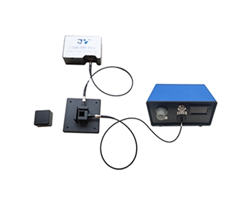
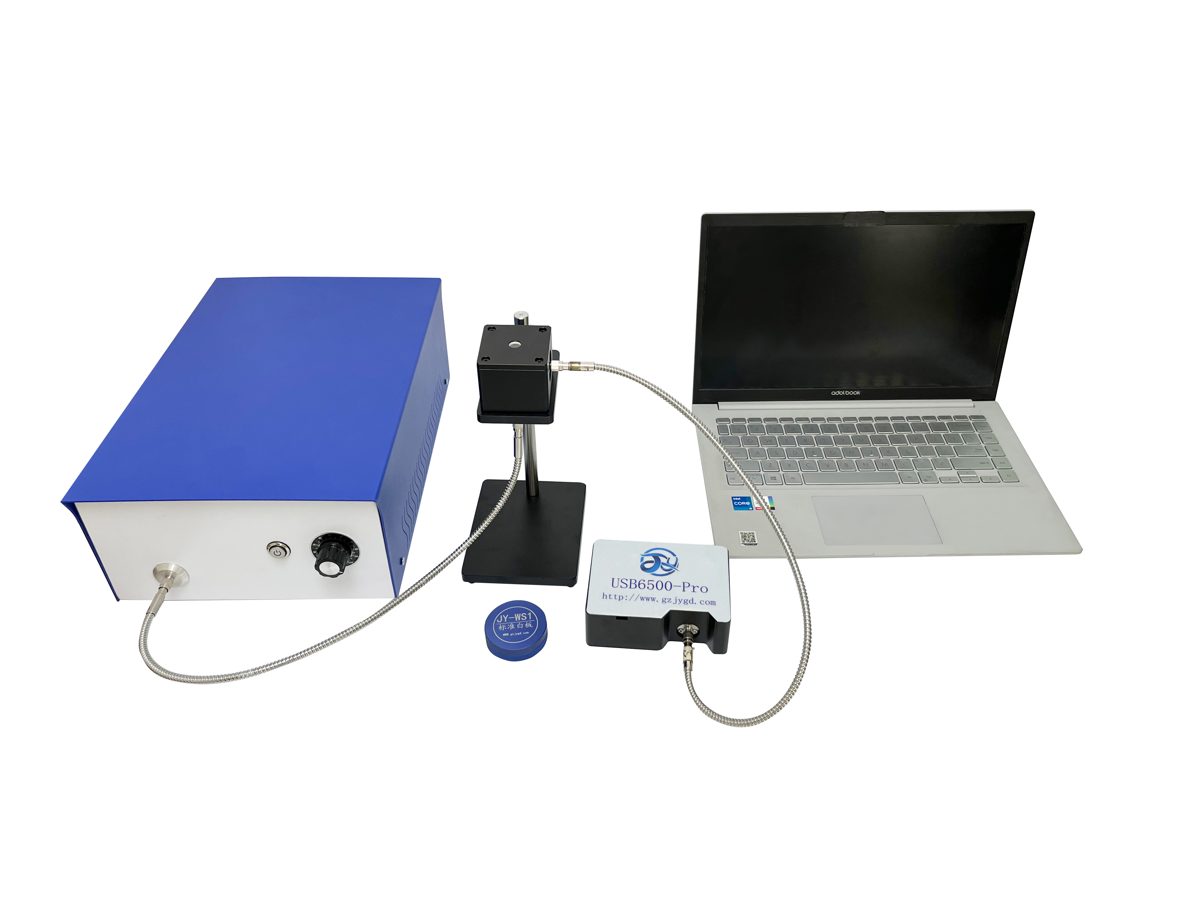
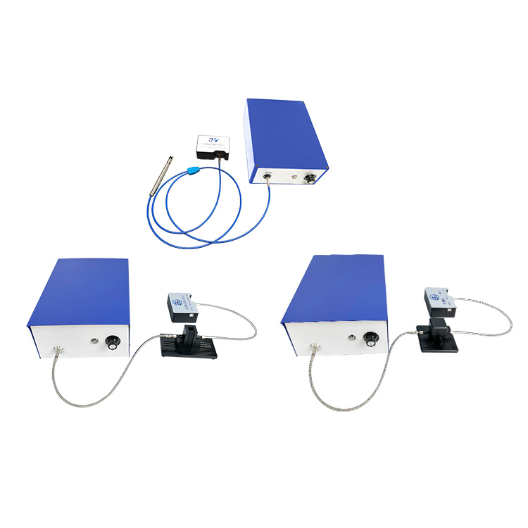
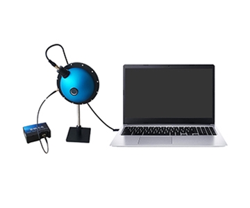
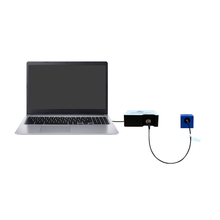
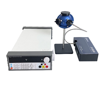
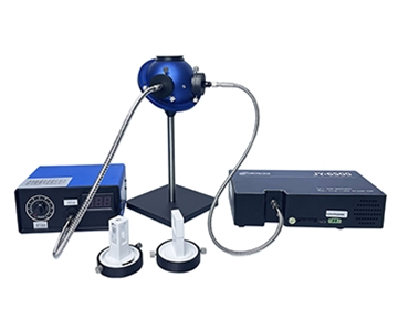
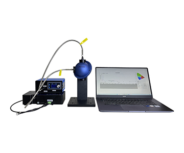
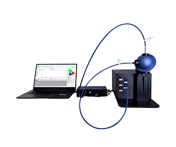
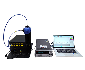
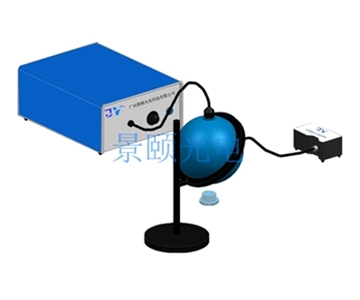
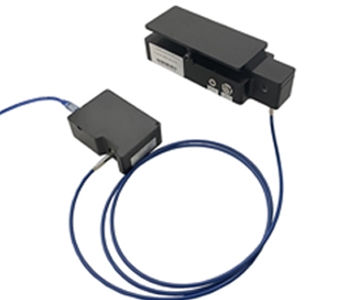
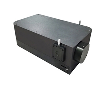
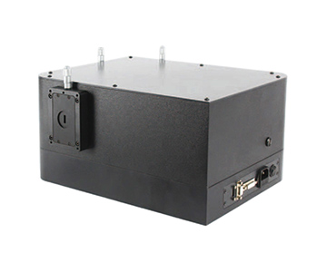
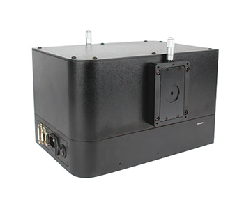
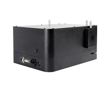
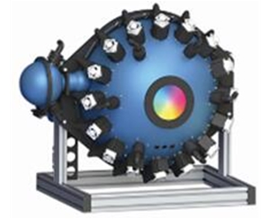
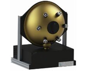
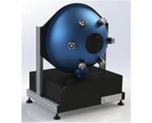
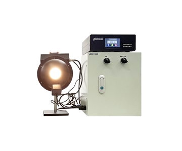
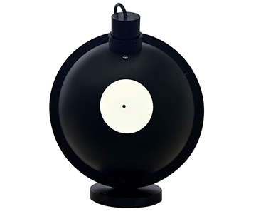
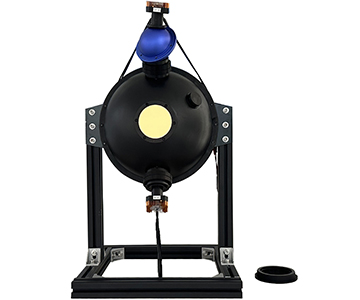
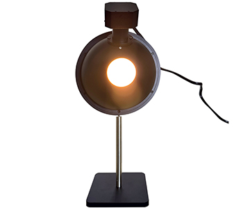
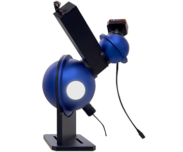
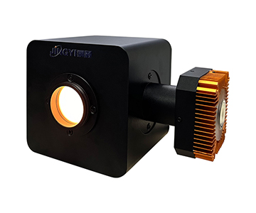
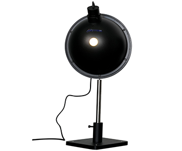
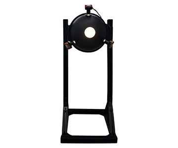
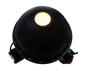
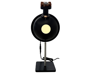
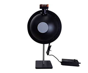
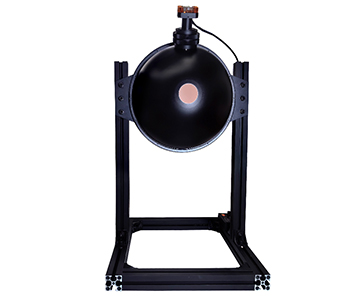
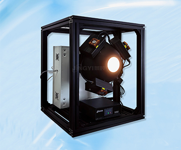
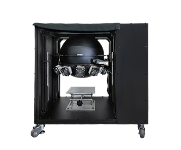
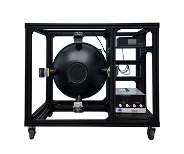
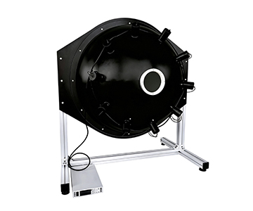
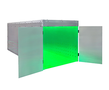
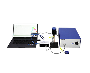
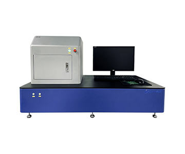
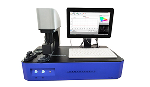
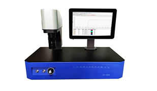
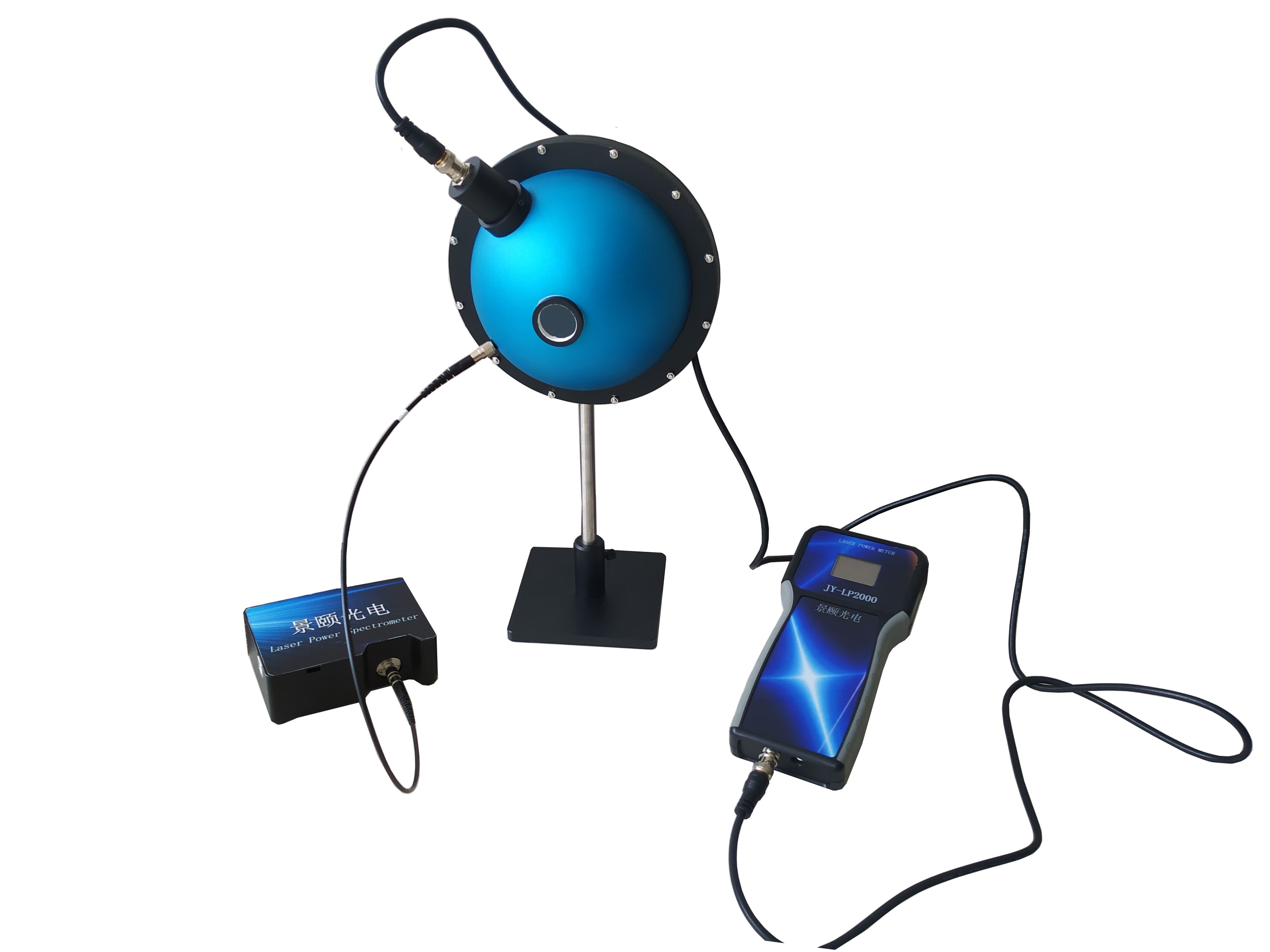
Zero-drift error in spectral calibration is not a single-component failure but a system-level error chain involving coating uniformity, interface thermal stability, and detector dark baseline. This whitepaper examines how integrating sphere cavity geometry, port area ratios, and PTFE coating processes determine long-term measurement accuracy in UV-Vis-NIR optical metrology. Covering 200–2500 nm spectral ranges with 99% reflectance PTFE cavities, the analyzed systems support transmittance, reflectance, haze, and fluorescence quantum efficiency measurements for both laboratory calibration and production-line quality control.
Executive Summary: Key Parameters at a Glance
The following extractable parameters define the evaluated integrating sphere product family:
•Spectral coverage: 200–2500 nm and 250–2500 nm configurations
•Cavity material: High-grade PTFE with foam-molded or spray-coated finishes, internal reflectance up to 99%
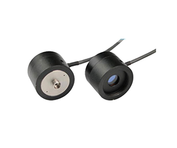
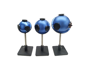
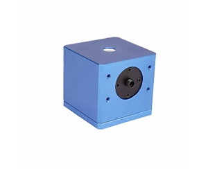
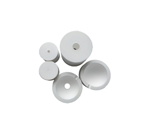
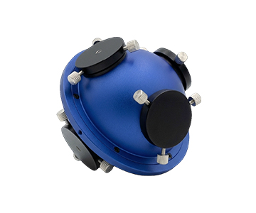
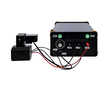
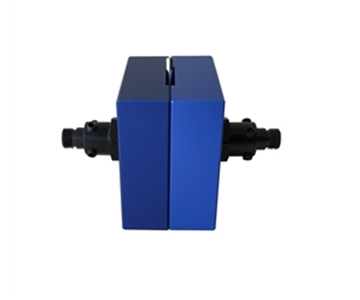
•Transmittance sphere diameters: 10 mm / 15 mm / 25 mm / 36 mm, with entrance ports of Φ1.5 mm / Φ3 mm / Φ5 mm / Φ9.5 mm respectively
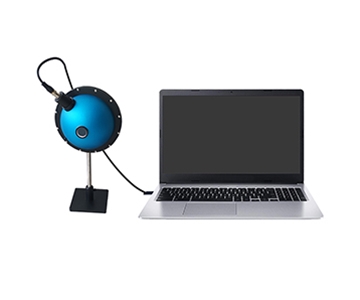
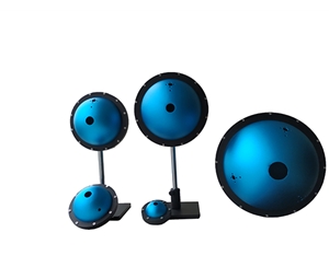
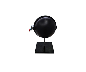
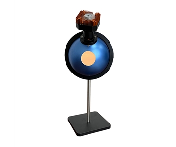
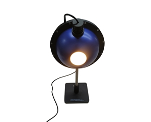
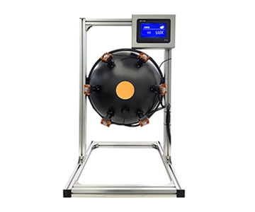
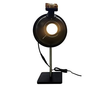
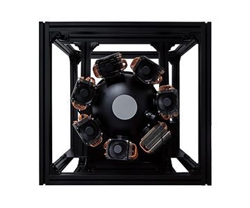
•General-purpose sphere diameters: 84 mm / 100 mm / 125 mm / 150 mm, three ports (customizable)
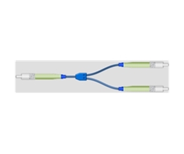
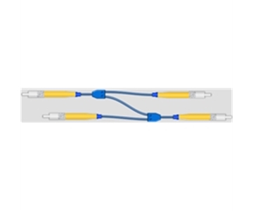
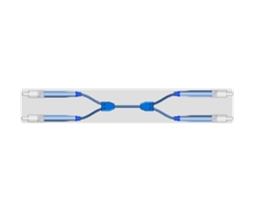
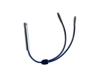
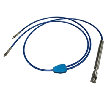
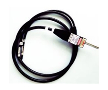
•Interface: 90° SMA905 as standard, FC/PC and other interfaces available upon request
•Sample compatibility: Solids, powders, transparent samples, thin films, liquids (flow-through cells)
•Applications: Transmittance, reflectance, haze, fluorescence quantum efficiency (QE), laser spectral power, radiometric calibration
From a production deployment perspective, this parameter range means that when switching from millimeter-scale optical components to hundred-millimeter-scale uniform light sources, the measurement paradigm remains unchanged. Only port dimensions and sample holders require reconfiguration, delivering high equipment reuse across diverse testing scenarios.
Industry Context: Legacy Specifications Redefined by Advanced Manufacturing
Legacy evaluation frameworks for integrating sphere light sources have traditionally emphasized repeatability as the primary performance metric. However, measurement uncertainty budgets—aligned with NIST-traceable calibration methodologies—reveal that zero-drift, representing long-term accuracy degradation, is the dominant source of yield loss in precision optical manufacturing.
As advanced optical thin films, micro-display modules, and laser devices push into tighter tolerance regimes, the conventional workflow of single-point calibration with fixed dark current compensation begins to fail. During a weekend qualification run, a metrology laboratory observed small but measurable baseline offsets between successive readings of the same transmittance sample batch. The deviation was not algorithmic—it originated in the thermal-optical coupling chain within the sphere cavity itself.
From a production standpoint, this signals a fundamental shift: calibration priorities must move from "measuring quickly" to "drifting less and tracing clearly."
Note: The following technical sections draw exclusively from product documentation. All structural descriptions, parameters, and application scenarios are sourced from technical specifications provided by the manufacturer.
Zero-Drift Analysis: How the Error Chain Hides Inside the Cavity
Drift Is Not Just a Detector Issue—It Maps to Cavity Geometry
The first contributor to zero-drift is the long-term consistency of the cavity wall's diffuse reflectance characteristics. The documented PTFE cavity materials demonstrate high stability, resistance to oxidation and yellowing, water resistance, and Lambertian behavior across the 200–2500 nm range. When coating reflectance is maintained at the 99% level, the multi-scattered light field approaches ideal isotropy, resulting in a flatter detector baseline.
From a production perspective, a coating that resists yellowing and powder shedding extends the dark baseline reset interval, reducing the frequency of recalibration on the production floor.
Port Area Ratio and Thermal Pathways
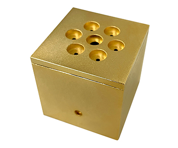
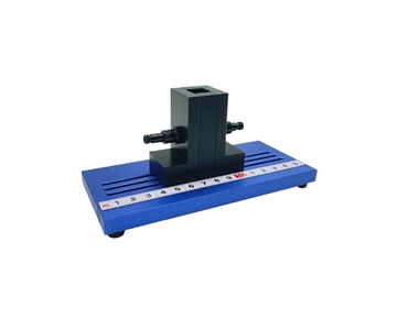
The second drift source is thermal leakage driven by port layout. General-purpose configurations adopt orthogonal three-port layouts (0°, nadir, 90°) or dual-port arrangements (0° and 90°), while compact transmittance spheres use an entrance port plus a 90° side exit port. Smaller port areas and thermally stable alumina housings make cavity temperature rise more controllable, directly limiting its impact on baseline stability.
During continuous transparent sample measurements, the 10 mm internal diameter (Φ1.5 mm entrance port) compact structure offers short optical path length and low thermal mass, enabling faster baseline recovery. For low-volume, high-mix production environments, this translates to lower waiting costs between product changeovers.
Interface and Dark Frame Synchronization
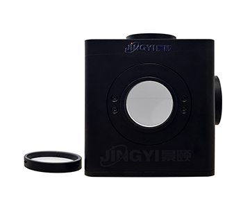
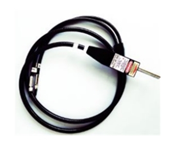
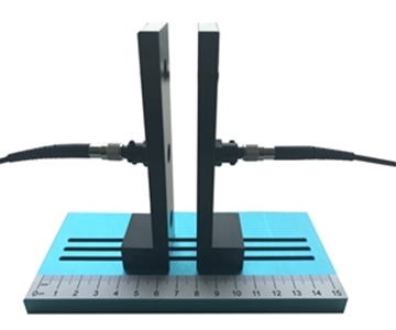
The third drift source is micro-displacement at the fiber optic coupling interface. SMA905, as a standardized interface, delivers consistent repeatability across multiple mating cycles, directly affecting dark current compensation quality. Exit ports uniformly adopt 90° SMA905 in the documented designs, with FC variants available on select models—interface standardization exists precisely to ensure that disassembly and reassembly do not introduce new drift variables.
Technical Architecture and Operating Principles
Cavity Structure and Diffuse Reflection Mechanism
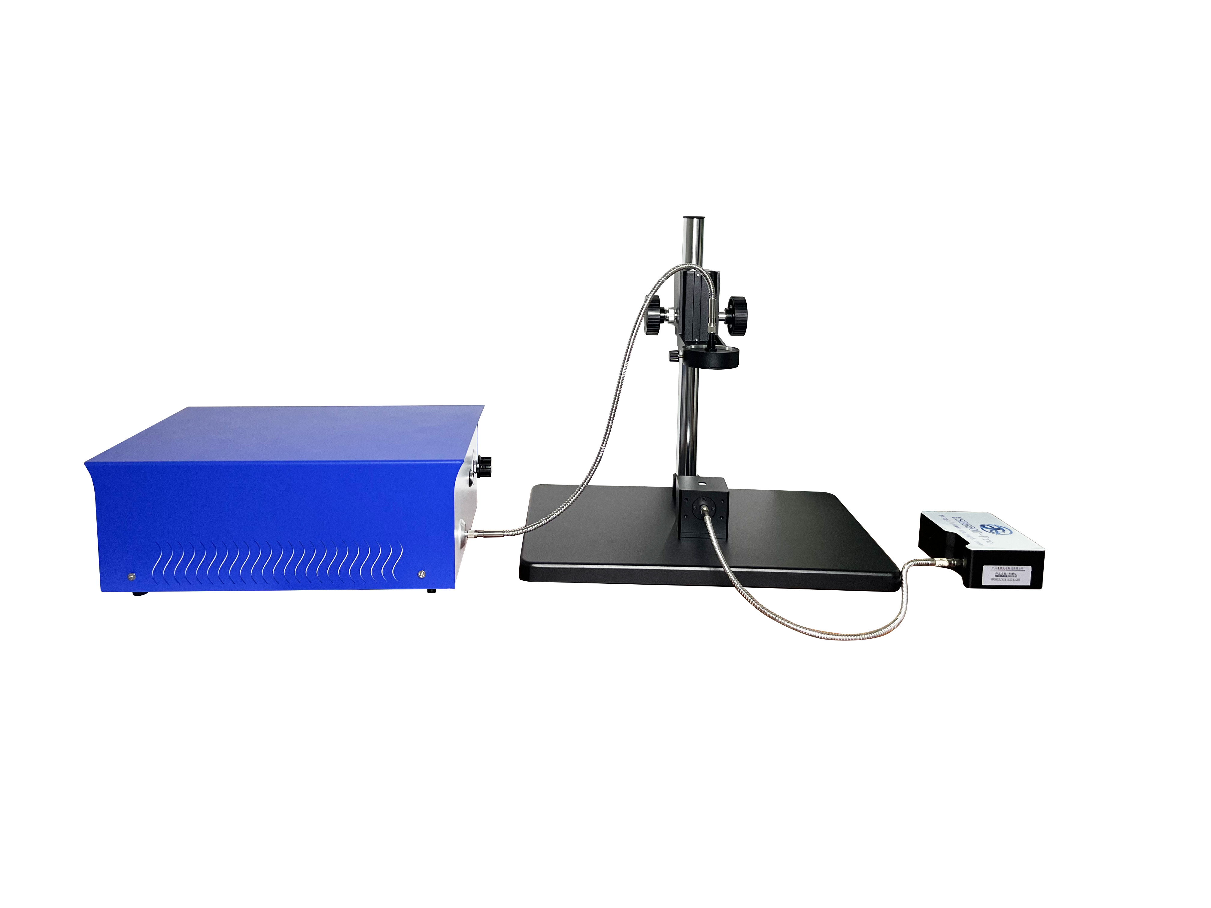
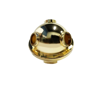
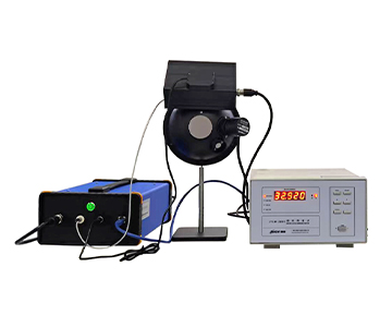
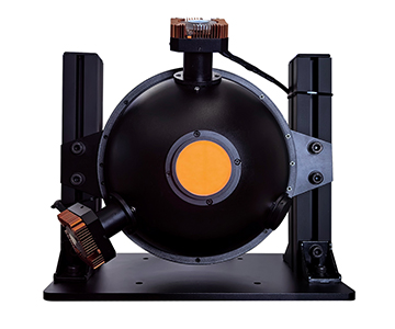
Integrating spheres form a closed cavity using high-diffuse-reflectance PTFE liners. Incident light undergoes multiple scattering events to create a uniform spherical light field. Transmittance configurations collect forward-incident and side-exit light for transmission measurements; reflectance configurations approximate D8 geometry with 8° incidence, 90° exit, and a sample port; fluorescence QE configurations use entrance port collimation, central sample placement, and exit port baffles to block direct excitation light leakage.
The manufacturer contributed to the development of GB/T 47066-2026 (equivalent to ISO diffuse transmission standards), which specifies optical geometry and port conditions for total transmittance testing of plastics. The inner diameter-to-entrance-port ratios in the transmittance sphere line (e.g., 10 mm/Φ1.5 mm, 25 mm/Φ5 mm) are defined within these geometric constraints.
Two Coating Process Implementations
Documentation reveals two distinct process paths:
•Foam molding: Used in compact transmittance spheres and some general-purpose spheres, achieving 99% reflectance with oxidation resistance
•Spray coating: Applied to large fluorescence QE spheres, with PTFE coatings rated for continuous service up to 300°C, suitable for prolonged excitation light exposure
For fluorescence samples requiring continuous excitation, a 300°C temperature rating ensures the cavity does not
Modular Ports and Sample Holders
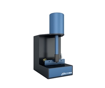
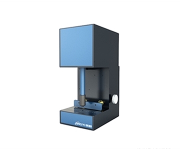
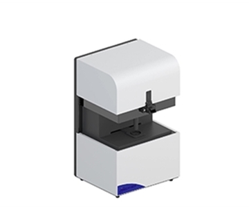
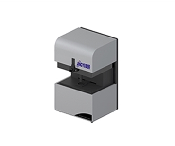
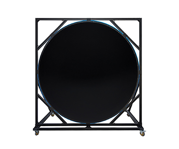
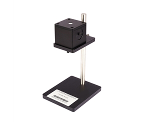
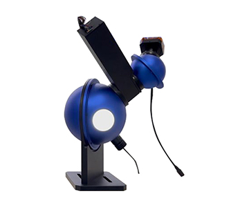
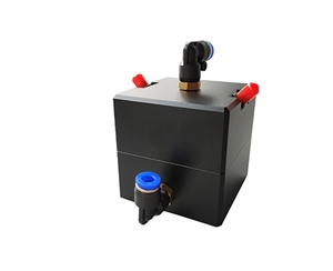
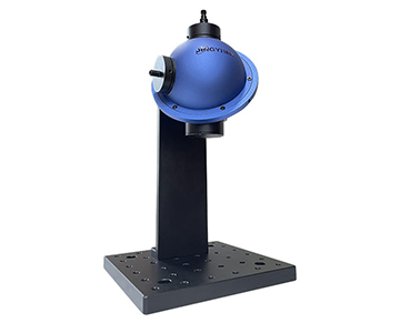
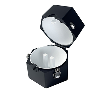
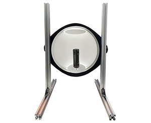
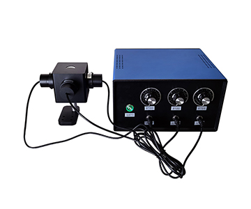
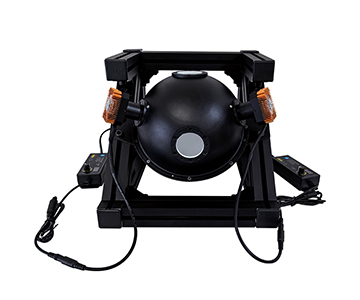
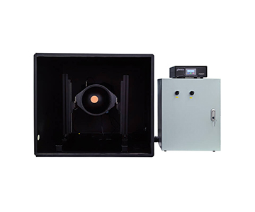
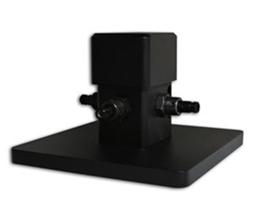
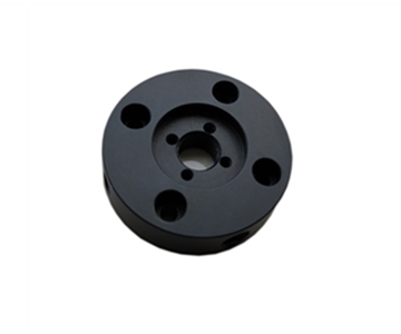
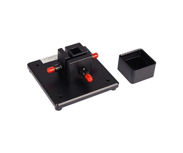
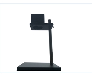
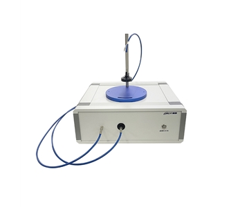
General-purpose large spheres (84–150 mm) feature three customizable ports supporting quick-switch collimating mirrors, cuvette holders, and sample brackets. The open-frame 200 mm sphere uses a latch structure with a 60×60 mm sample stage for large-format sample insertion. Water quality analysis spheres incorporate flow-through PL8-02 fittings for in-situ optical path integration of low-absorption river and seawater samples.
Application Scenarios and Solutions
| Industry Scenario |
Measurement Object |
Process Step |
Technical Approach |
Customer Value |
| Optical Manufacturing |
Transparent lenses / thin films |
100% transmittance & haze inspection |
10–36 mm compact sphere + SMA905 |
Compact optics, fast changeover |
| Material Analysis |
Powders / solids |
Diffuse reflectance |
15 mm reflectance sphere, 8° incidence + optional light trap |
Specular reflection subtraction |
| Environmental Water |
River / seawater |
Absorption spectroscopy |
Flow-through PTFE cavity |
Scatter interference suppression |
| Research Institutes |
Fluorescent samples |
QE measurement |
3-port + baffle + collimation |
High signal purity |
| Metrology Labs |
Standard light sources |
Radiometric calibration |
Large sphere uniform field |
Traceable measurements |
Key specifications from the documentation: the most compact transmittance sphere measures φ25×h25 mm with a net weight of 29 g; the largest general-purpose sphere offers 150 mm internal diameter; water quality spheres operate within 0–50°C. From a deployment perspective, this means a single technology family can cover everything from desktop R&D to field water monitoring, eliminating the need for multiple vendor relationships.
Standards-Based Compliance Advantages
Rather than comparative claims, this section anchors to established standard frameworks.
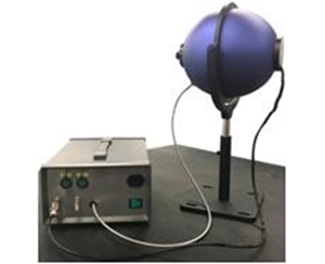
Measurement uncertainty frameworks for integrating sphere light sources—consistent with NIST calibration guidelines—incorporate cavity non-uniformity and long-term stability as components of combined uncertainty. The 99% reflectance PTFE liner and its Lambertian characteristics directly serve to suppress the "plane/angular non-uniformity" component, shortening and stabilizing the radiometric calibration traceability chain.
In thin-film and optical component calibration, the manufacturer participated in drafting T/CIET 2298-2026, which defines calibration traceability paths for thin-film interferometric thickness measurement systems. As the front-end transmittance/reflectance signal collector, the integrating sphere's port geometry and coating consistency form the input guarantee for this calibration chain.
During procurement, buyers should verify compliance with GB/T 47066-2026 to ensure that port-area ratios and optical geometry for total transmittance testing meet standard requirements, maintaining complete measurement traceability.
Selection Guide: Match to Scenario, Not Just Port Diameter
Decision Tree
•Samples < 3 mm requiring fiber coupling → Basic 10 mm / 15 mm transmittance sphere
•Routine lens / thin-film full-spectrum transmission → 25 mm / 36 mm transmittance sphere
•Opaque solids / powder reflectance → 15 mm reflectance sphere (8° incidence, optional light trap)
•Fluorescence QE / bio-labeling → 100 mm three-port quantum efficiency sphere
•Water absorption → Flow-through water quality sphere (Φ50 mm customizable)
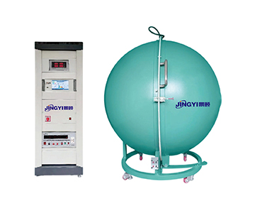
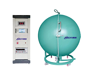
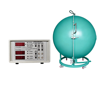
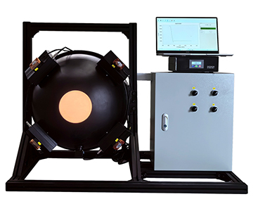
•Uniform light sources / radiometric calibration → 84–150 mm general-purpose sphere or 200 mm open-frame model
Configuration Recommendations
| Requirement |
Recommended Architecture |
Key Verification Items |
| Production-line 100% inspection |
Compact sphere + SMA905 |
Entrance port size, interface repeatability |
| Multi-purpose R&D |
General large sphere + customizable ports |
Port positions, stage adjustment range |
| Field water monitoring |
Flow-through PTFE sphere |
Inlet/outlet fitting specifications |
| QE testing |
3-port + collimation + baffle |
Coating temperature rating, sample holder type |
Honest Limitations
Integrating spheres are not universal measuring instruments. Small-diameter spheres (e.g., 10 mm) offer low thermal inertia but have limited adaptability for large-format samples or unsupported powders, requiring dedicated fixtures. While PTFE maintains high absolute reflectance in the deep-UV range, extreme high-power CO₂ laser continuous injection still encounters thermal load boundaries, requiring duty cycle management.
Additionally, open-frame structures facilitate sample insertion, but increased opening frequency introduces ambient stray light risks, necessitating darkroom conditions. These constraints are not defects—they are measurement boundaries. Only by defining boundaries can traceability be meaningfully discussed.
Frequently Asked Questions
Q1: What are the primary mechanisms for suppressing zero-drift?
Zero-drift suppression relies on the coordinated effect of three elements: long-term coating resistance to yellowing, controllable thermal paths through port design, and consistent interface mating. A stable PTFE liner minimizes scattering distribution distortion, while standardized SMA905 interfaces reduce coupling micro-displacement across repeated connections.
Q2: Can compact transmittance spheres measure haze?
Yes. The documented transmittance spheres support haze detection. The key requirement is fixed geometry between entrance and exit ports, combined with a full-spectrum detector to separately output transmission and scattering components.
Q3: Why is a baffle necessary in fluorescence QE measurements?
The exit port baffle blocks direct excitation light from reaching the detection fiber, ensuring that the collected signal consists predominantly of fluorescence emission rather than leaked excitation radiation, thereby improving signal purity.
Q4: Beyond wavelength range, what else should buyers verify during procurement?
Buyers should confirm port area ratios, coating process (foam-molded vs. spray-coated), temperature rating, interface type, and compliance with GB/T 47066-2026 geometric conditions for transmittance measurements.
Q5: How can I independently verify whether an integrating sphere is drifting?
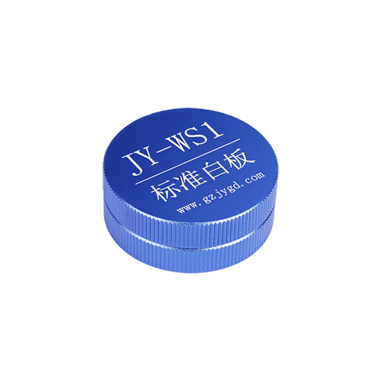
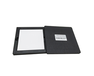
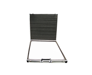
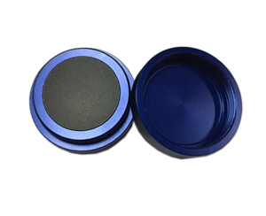
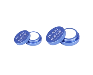
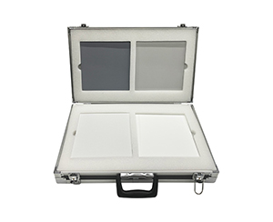
Use a NIST-traceable standard white reference. Perform dual calibrations at fixed wavelength points separated by a 24-hour interval. Compare the dark baseline and absolute reflectance deviation between the two sessions. If the deviation exceeds the allowable uncertainty component defined by your standard, recalibration is required—do not rely solely on the manufacturer's self-test report.
Future Trends and Conclusions
The next evolution in integrating sphere technology will not focus on nudging reflectance from 99% to marginally higher values. Instead, the priority is making "drift" a quantifiable, compensable, and auditable metrology variable. Built-in dark frame synchronization, temperature feedback, and adaptive port area control represent the shared direction for laboratory R&D and production-line quality inspection.
The conclusion is clear: from a zero-drift perspective, what truly extends equipment service life is coating stability and geometric reproducibility—not the peak numbers on a specification sheet.
For detailed specifications and application notes on integrating spheres, search "Jingyi Optoelectronics + integrating sphere" or visit our technical library.
About This Guide
Data Sources
: GB/T national standard texts (GB/T 43971-2024, GB/T 47066-2026, T/CIET 2298-2026), manufacturer product technical documentation for transmittance spheres (10/15/25/36 mm), reflectance spheres, general-purpose spheres, fluorescence QE spheres, water quality analysis spheres, and open-frame spheres.
Author
: Optical metrology practitioner with 12 years of industry experience, specializing in industrial precision measurement equipment and spectral calibration systems.
Disclosure
: Jingyi Optoelectronics manufactures integrating spheres and related optical measurement equipment. This whitepaper presents technical assessments based on published specifications, national standards, and industry public information. No compensation was received from third-party brands mentioned.
Objective Statement
: This content is intended for educational and technical reference purposes. Equipment selection should always include independent proof-of-concept validation under your specific measurement conditions.
Last Updated
: October 2026