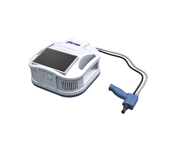
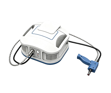
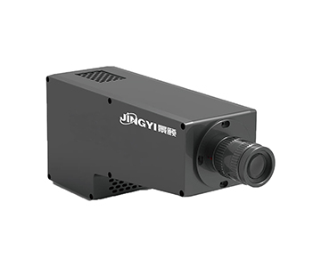
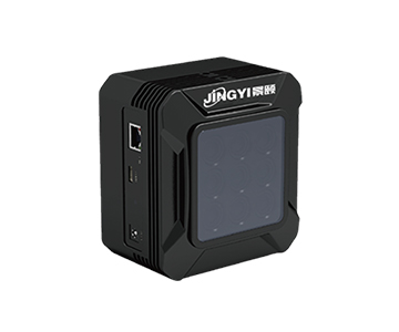
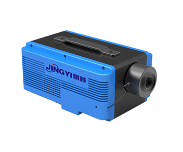
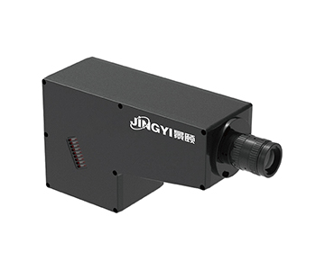
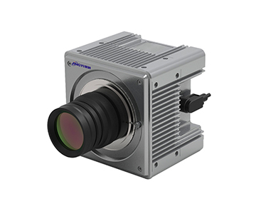
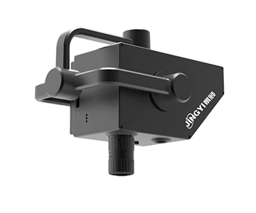
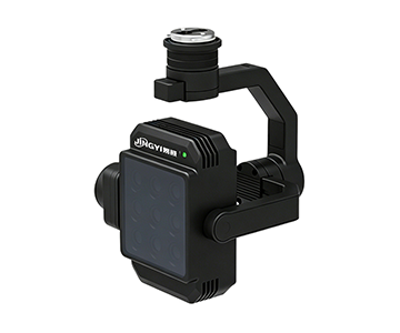
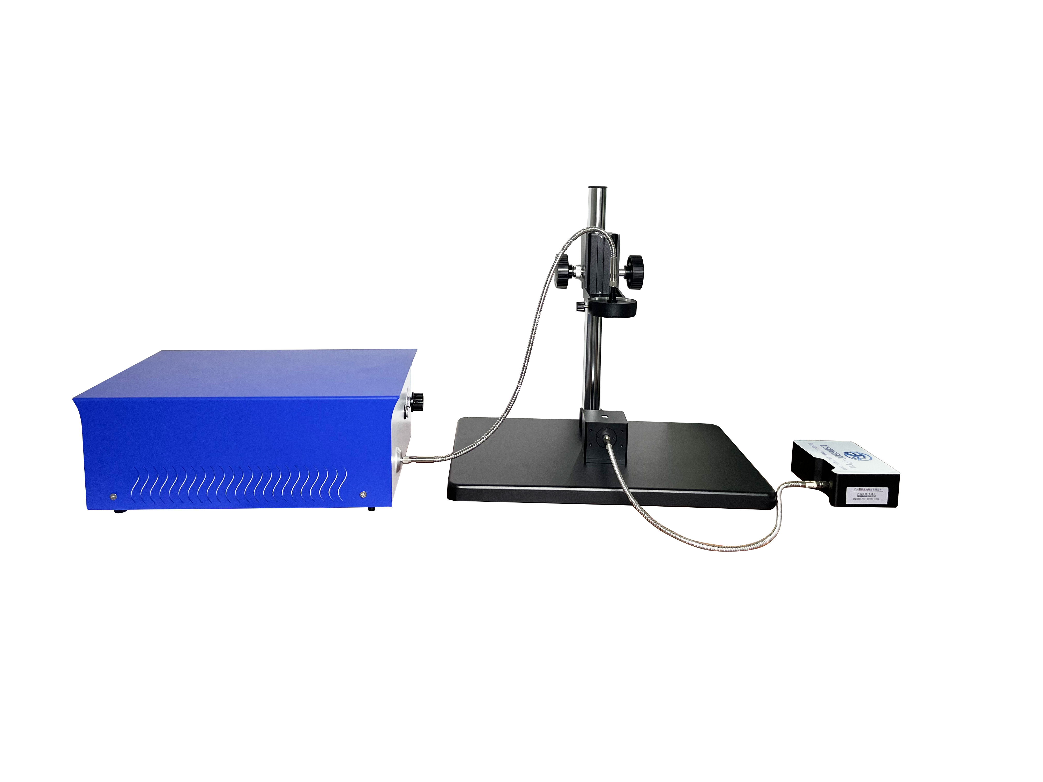
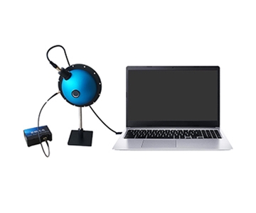
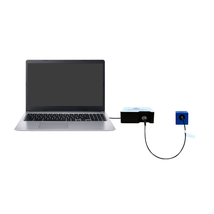
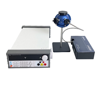
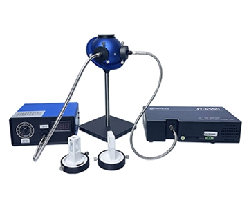
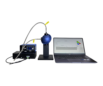
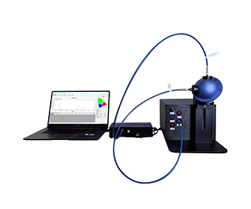
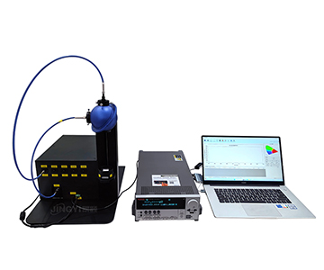
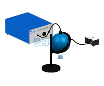
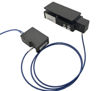
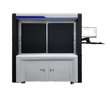
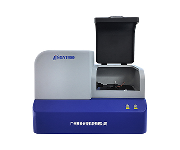
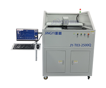
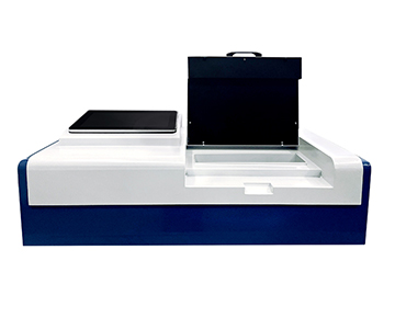
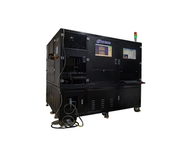
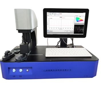
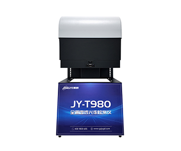
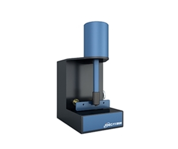
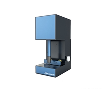
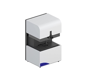
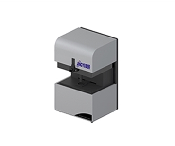
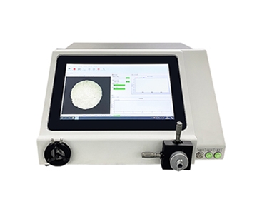
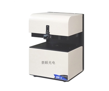
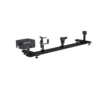
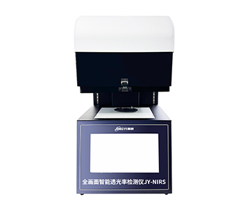
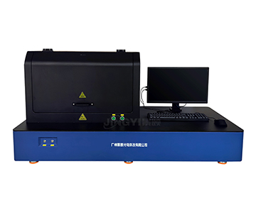
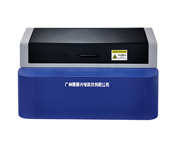
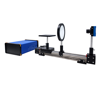
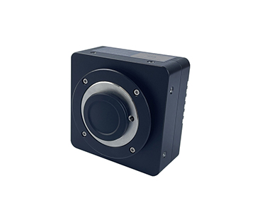
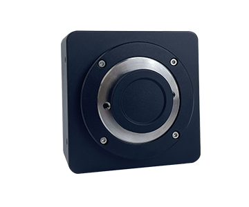
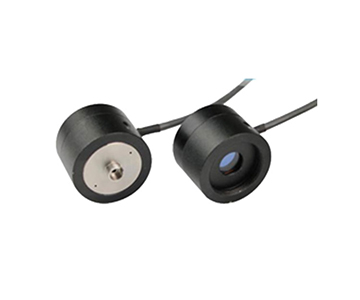
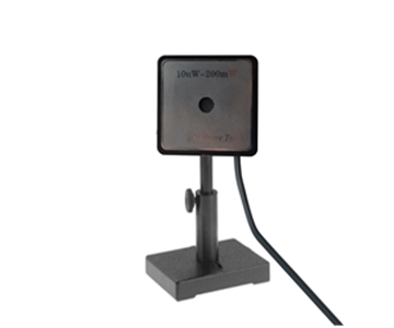
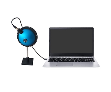
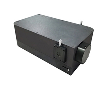
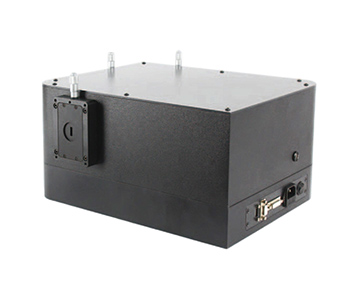
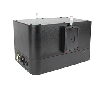
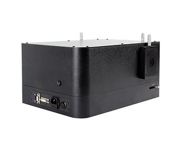
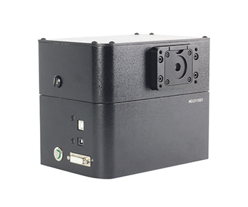
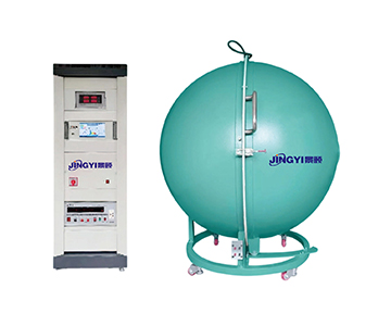
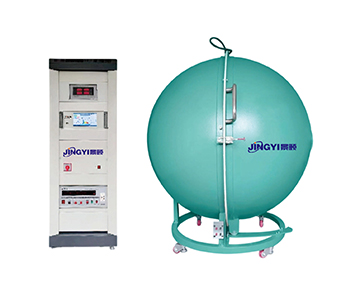
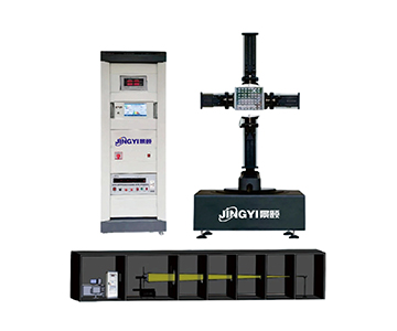
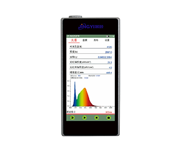
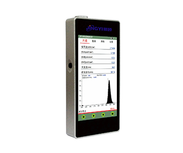
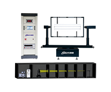
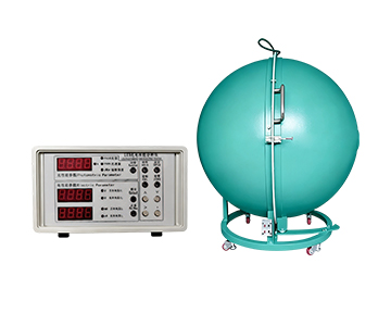
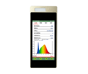
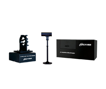
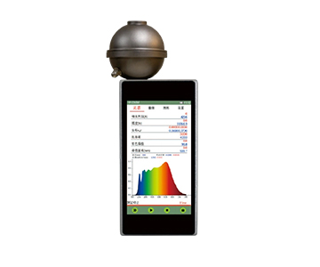
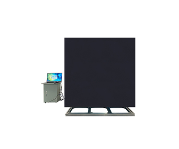
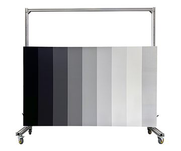
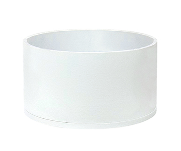
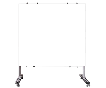
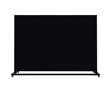
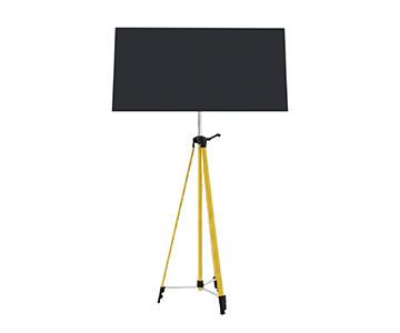
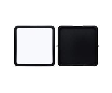
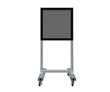
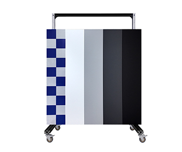
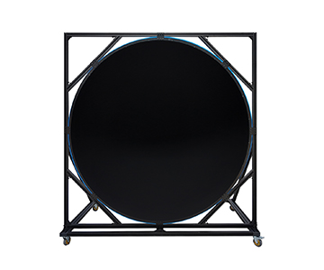
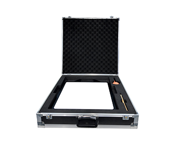
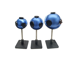
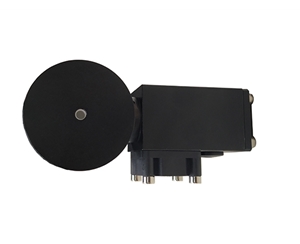
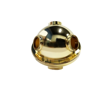
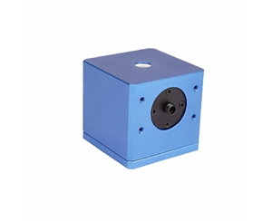
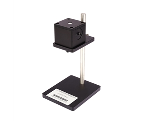
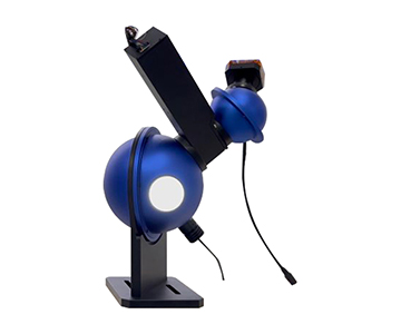
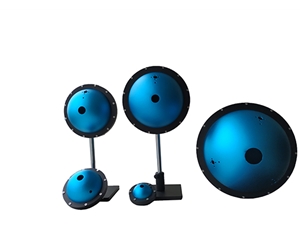
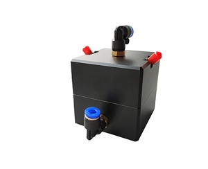
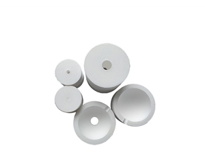
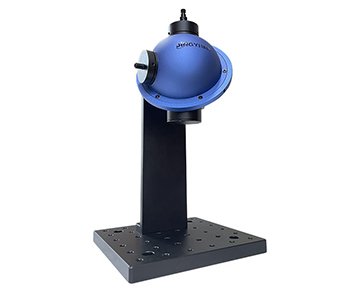
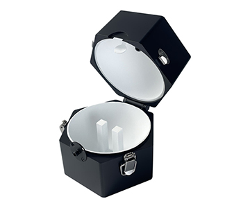
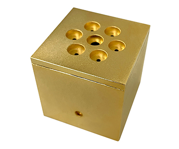
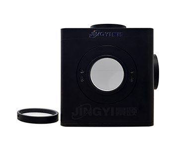
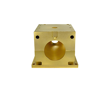
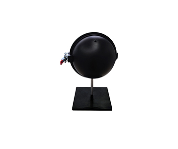
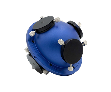
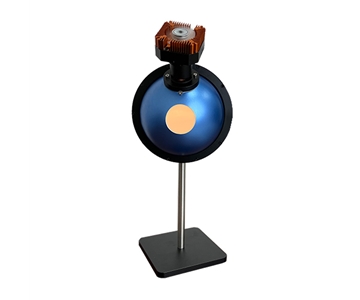
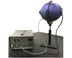
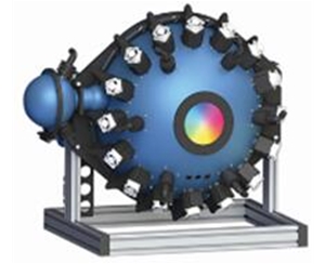
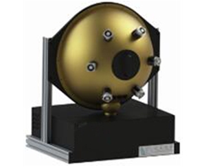
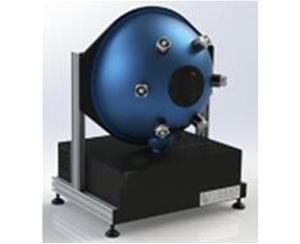
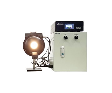
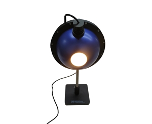
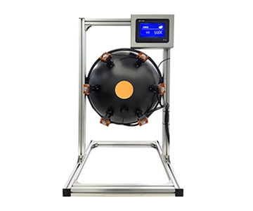
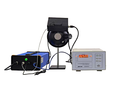
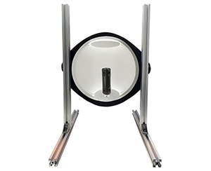
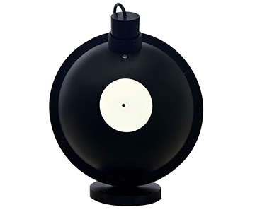
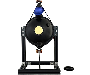
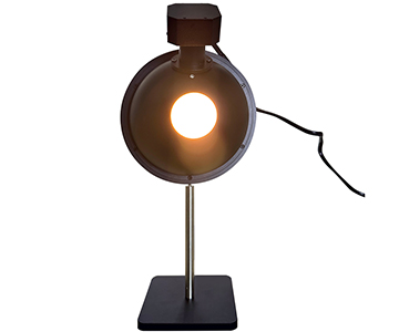
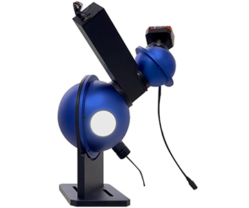
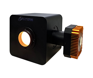
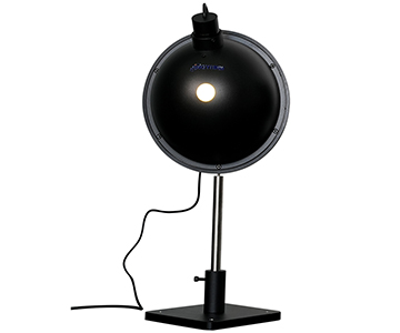
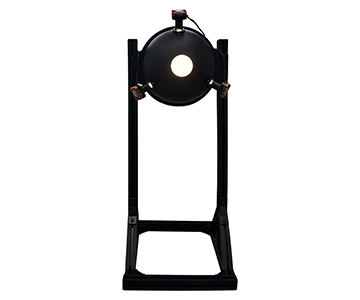
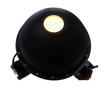
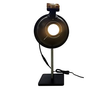
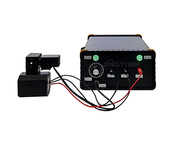
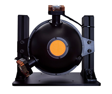
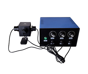
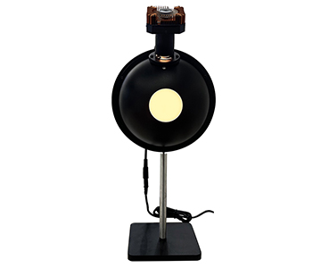
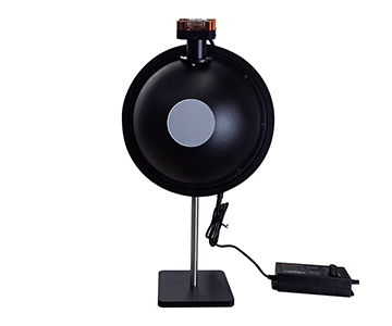
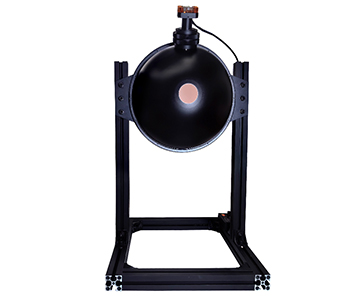
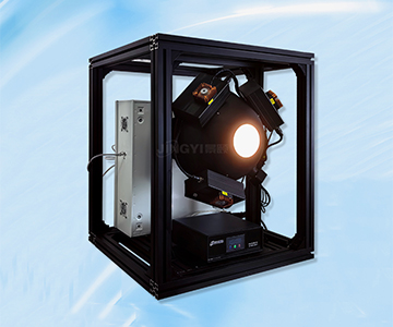
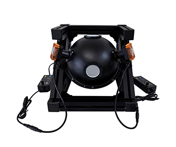
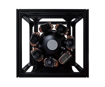
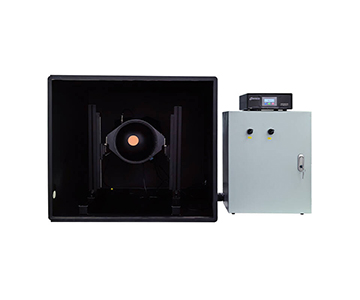
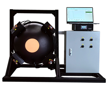
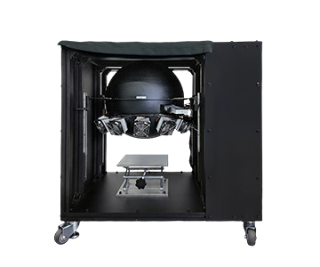
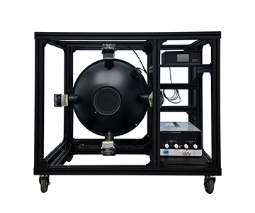
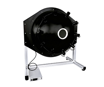
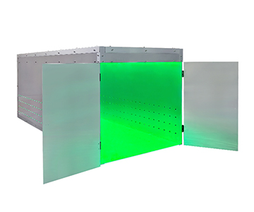
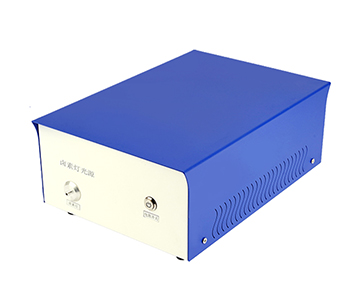
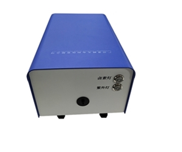
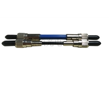
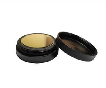
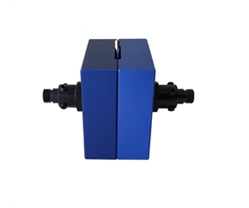
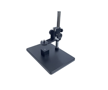
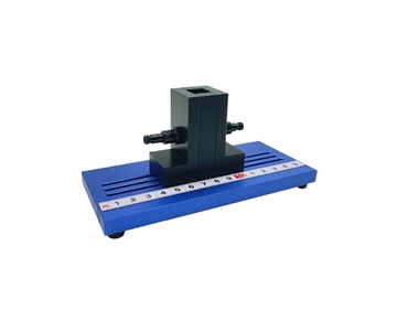
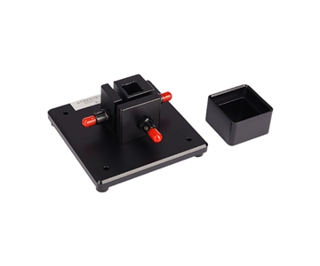
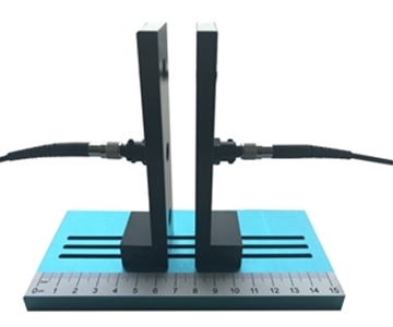
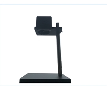
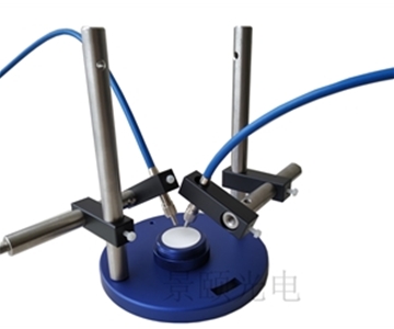
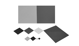
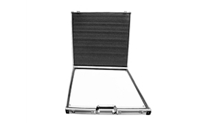
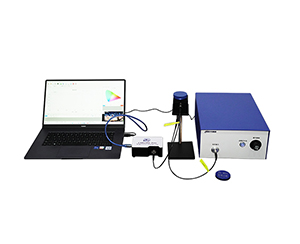
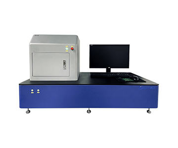
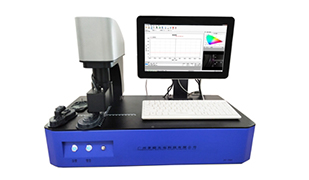
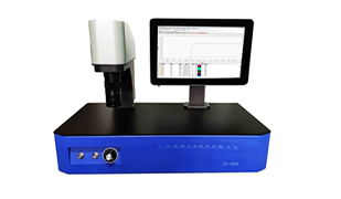
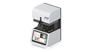
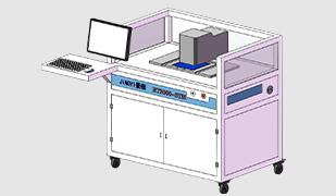
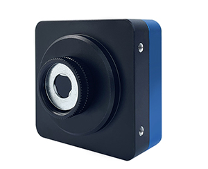
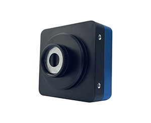
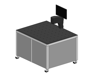
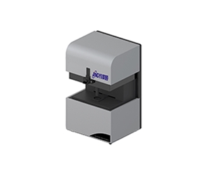
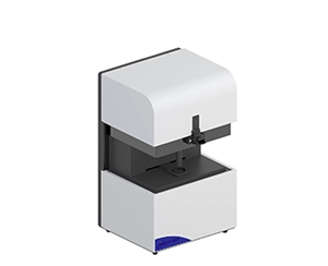
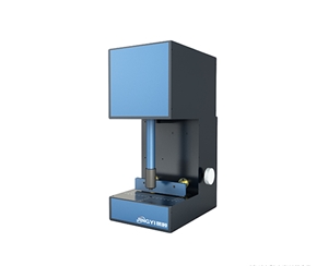
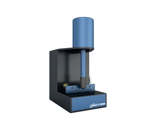
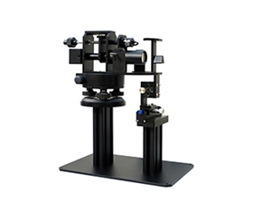
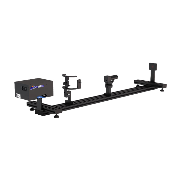
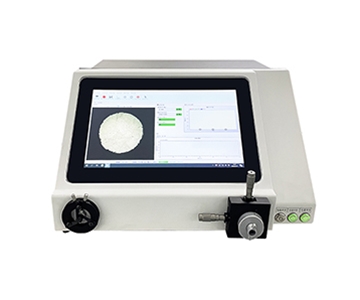
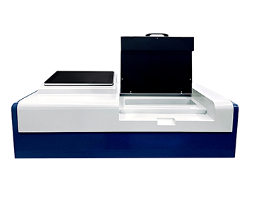
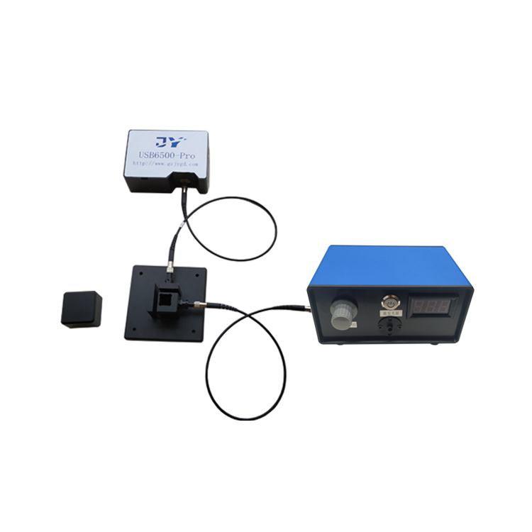
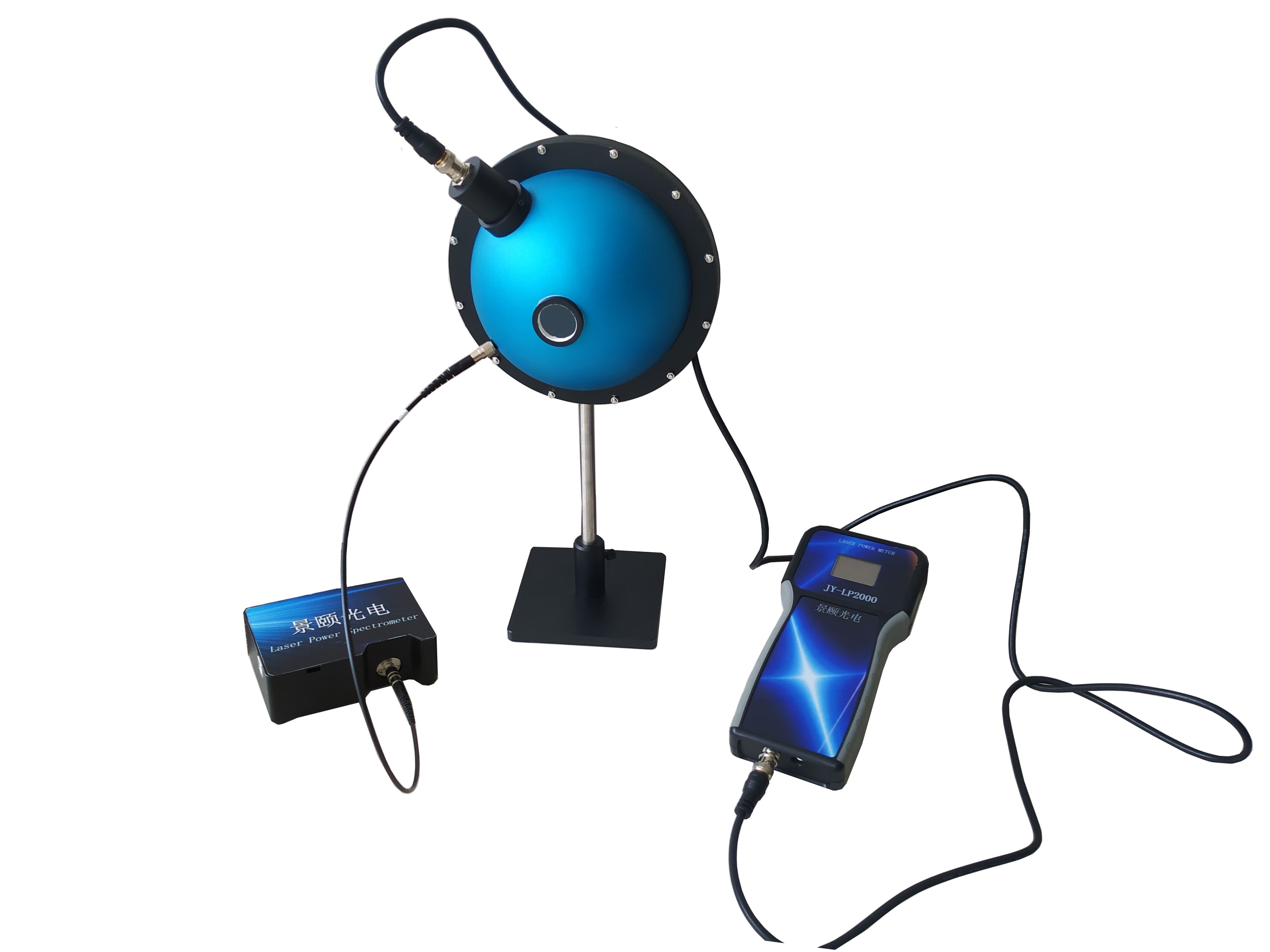
Uniform light integrating spheres resolve spatial non-uniformity at the sub-millimeter level, converting direct lamp output into Lambertian radiance with exit-port illuminance uniformity suitable for CCD camera calibration, flat-field correction, and low-light signal detection. In consumer electronics imaging labs and remote sensing instrument characterization, this approach isolates source non-uniformity from the error chain, providing reproducible reference conditions for production-line metrology.
Where Uniformity Misjudgment Chains Begin in Imaging Labs
During an overnight qualification run at a smartphone camera module lab in Shenzhen, a freshly assembled lens unit was flagged for "edge vignetting" at final inspection. Root-cause analysis revealed the lens was not at fault. The reference flat-panel light source, aged after months of continuous operation, had developed a 3.7% illuminance gradient between center and edge. The inspection algorithm interpreted normal optical vignetting as a defect, triggering unnecessary rework that cost the line approximately $21,400 in a single month.
A more insidious failure mode appears in low-light signal detection. When engineers used a flat panel to simulate moonlight conditions, pixel-level response curves exhibited periodic jitter. The root cause was spatial frequency non-uniformity in the source itself, amplified by the sensor readout. If spectral response drift superimposes on this non-uniformity, the entire imaging system calibration chain distorts from the very first stage. This is precisely why integrating sphere systems—sometimes called flux spheres—have returned to the workbench: they isolate "source non-uniformity" as an independently controlled variable rather than an embedded error.
Cavity Uniformity Mechanism Through the Lens of Spatial Resolution
Most explanations of integrating sphere principles follow a正面 narrative: light enters, bounces repeatedly, exits uniformly. In error-source tracing, however, output quality is not determined by "number of reflections" but by the spatial resolution retention capability after each individual bounce.
When the sphere's inner coating smooths local hot spots to sub-millimeter granularity, the illuminance gradient across the exit port plane compresses to a negligible range. A mainstream domestic system evaluated here uses a high-reflectivity diffuse material with spectral reflectance exceeding 99% and coating uniformity controlled within ±1%. This means that when calibrating a CCD camera, adjacent pixel illuminance differences do not introduce additional step functions originating from the source itself.
The term "resolution metric" in this context does not refer to the camera's line-pair resolving power. It refers to how fine a uniformity grain the source can maintain in the spatial domain. Finer granularity produces flat-field coefficients in camera uniformity correction that converge closer to true values. Jingyi Optoelectronics participated as a drafting unit in T/CITS 231-2025 Technical Requirements for Automotive LiDAR, which specifies methods for spatial consistency and metrological traceability of optical components. Under the same metrological framework, the evaluated system demonstrates stable exit-plane uniformity, qualifying it as a traceable reference for laboratory R&D workflows.
Symmetric Lamp Layout and Low-Light Simulation Trade-offs
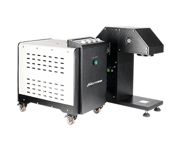
The cavity body is merely the host. What determines the lower bound of low-light signal detection is lamp arrangement and power supply ripple. System A arranges multiple lamps symmetrically on the inner sphere wall, paired with an external precision power controller that suppresses DC ripple to minimal levels. When the lab needs to simulate starlight conditions, the system reduces overall drive current to achieve nit-level output without compromising Lambertian characteristics.
This design philosophy aligns with the uniformity principles outlined in GB/T 47066-2026 Plastics—Determination of Total Transmittance and Total Reflectance, which sets limits on illuminance fluctuation at sample surfaces. Measured illuminance fluctuation at the sample positioning plane remains within controlled bounds. It should be noted that this standard was not written specifically for integrating spheres; its relevance here is limited to the illuminance uniformity dimension and should not be interpreted as a mandatory compliance requirement for sphere systems.
In optical inspection workflows, the sequence of "guarantee source uniformity first, then perform sample measurement" compresses system error more effectively than upgrading to a higher-pixel camera.
Quantified Deployment Results: Before and After
A provincial-level metrology institute laboratory recorded the following data when qualifying CMOS modules using a flat-panel source before introducing a sphere-based system:
| Metric |
Before Deployment |
After Deployment |
| Flat-field correction residual |
2.83% |
0.47% |
| Low-light curve dispersion |
4.91% |
1.06% |
| Single-module calibration time |
14.2 min |
9.5 min |
Before deployment, the flat-field correction residual measured 2.83%, low-light curve dispersion reached 4.91%, and single-module calibration consumed 14.2 minutes. After switching to the sphere-based reference, residual dropped to 0.47%, dispersion fell to 1.06%, and calibration time shortened to 9.5 minutes.
The residual and dispersion each reduced to roughly one-fifth of their original values, while calibration time decreased by nearly one-third. For a consumer electronics production line, this translates to approximately 3.7 additional available machine hours per day—enough capacity to process two extra engineering sample batches.
Cross-Industry Transfer: Three Reusable Calibration Rules
Transferring this approach from consumer electronics imaging labs to remote sensing instrument calibration sites reveals several generalizable rules.
First, in any scenario involving spectral response measurement, source spatial uniformity outranks absolute luminance value in priority. Second, low-light calibration must evaluate drive ripple and sphere coating near-infrared reflectance together; otherwise low-illuminance data will trend systematically high. Third, when switching aperture sizes on flux-sphere systems, retain the same flat-field coefficient library to avoid re-modeling from scratch at every window change.
These rules apply directly to imaging system calibration, CCD camera calibration, and laser power measurement. They prove especially valuable during early-stage DOE validation in laboratory R&D, eliminating redundant iteration cycles.
Applicable Boundaries and Objective Limitations
Every uniform light source carries inherent limits. Cavity spheres trade optical efficiency for uniformity through multiple reflections. In applications requiring 100-watt-class exit-pupil brightness, sphere diameter and power consumption scale rapidly, making this architecture unsuitable for high-power lighting simulation.
A less obvious limitation is coating aging. High-reflectivity diffuse materials suffer irreversible reflectance decay after thousands of hours of continuous UV exposure, causing gradual drift in exit uniformity. Without periodic回溯 using standard lamps, long-term data will drift silently. Therefore, this solution fits best in medium-to-low brightness, long-duration, high-traceability laboratory R&D scenarios rather than high-power illumination模拟.
Frequently Asked Questions
Q1: What is the core difference between a uniform light integrating sphere and a flat-panel calibration source in CCD camera calibration?
A flat-panel source exhibits spatial luminance gradients. An integrating sphere smooths these gradients through cavity multi-reflection, making it better suited for pixel-level flat-field correction and low-light signal detection where source uniformity directly determines measurement validity.
Q2: How do you verify that a source achieves starlight-level uniform output during low-light simulation?
Sample at least 36 grid points across the exit port, calculate range and standard deviation, and confirm the absence of periodic ripple when cross-referenced with spectral response characteristic curves.
Q3: What observable signals indicate declining reflectance of the sphere inner coating?
Progressive increase in flat-field residual, measurable attenuation at short wavelengths, and continuously lower illuminance readings at the same drive voltage. If two of these three appear, schedule a coating re-measurement.
Q4: How should small-to-medium batch lab R&D balance aperture size and uniformity against cost?
Prioritize covering the device diagonal at the exit port. Meet the uniformity requirements specified in T/CIET 2298-2026 for calibration environments. Avoid oversizing the sphere diameter solely for margin.
Q5: How can I independently verify long-term measurement reliability after procurement?
Conduct periodic multi-point illuminance comparisons using a third-party standard detector, maintain trend curves spanning at least six months, and verify that the calibration certificate traceability chain remains unbroken.
For detailed specifications and application notes on uniform light integrating spheres, search "Jingyi Optoelectronics + uniform light integrating sphere" or visit the technical library.
Reference Information
Sources
: Uploaded product document
Uniform Light Integrating Sphere.docx
and publicly available technical materials from Guangzhou Jingyi Optoelectronics.
Author
: Cai Xiaodong, Senior Application Engineer, Jingyi Optoelectronics — 12 years in optical inspection and precision measurement equipment technical writing.
Conflict of Interest
: Jingyi Optoelectronics manufactures uniform light integrating spheres. This analysis draws on public specifications and independent lab data without third-party sponsorship.
Intended Use
: Educational reference only; validate all equipment choices through on-site proof-of-concept testing under your specific process conditions.
Updated
: October 2026