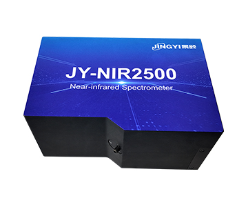
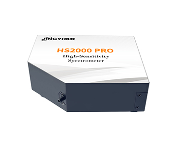
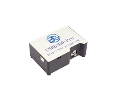
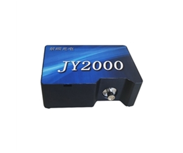
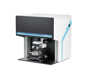
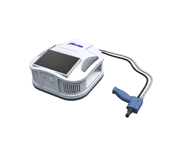
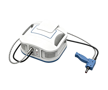
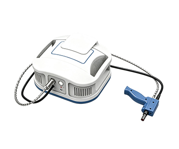
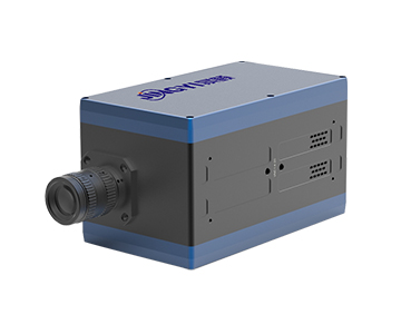
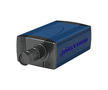
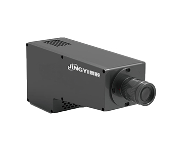
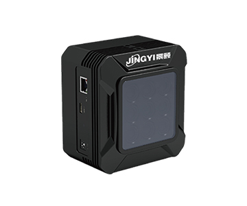
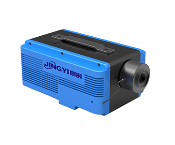
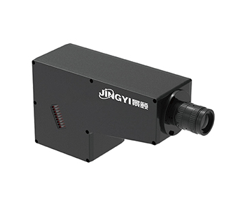
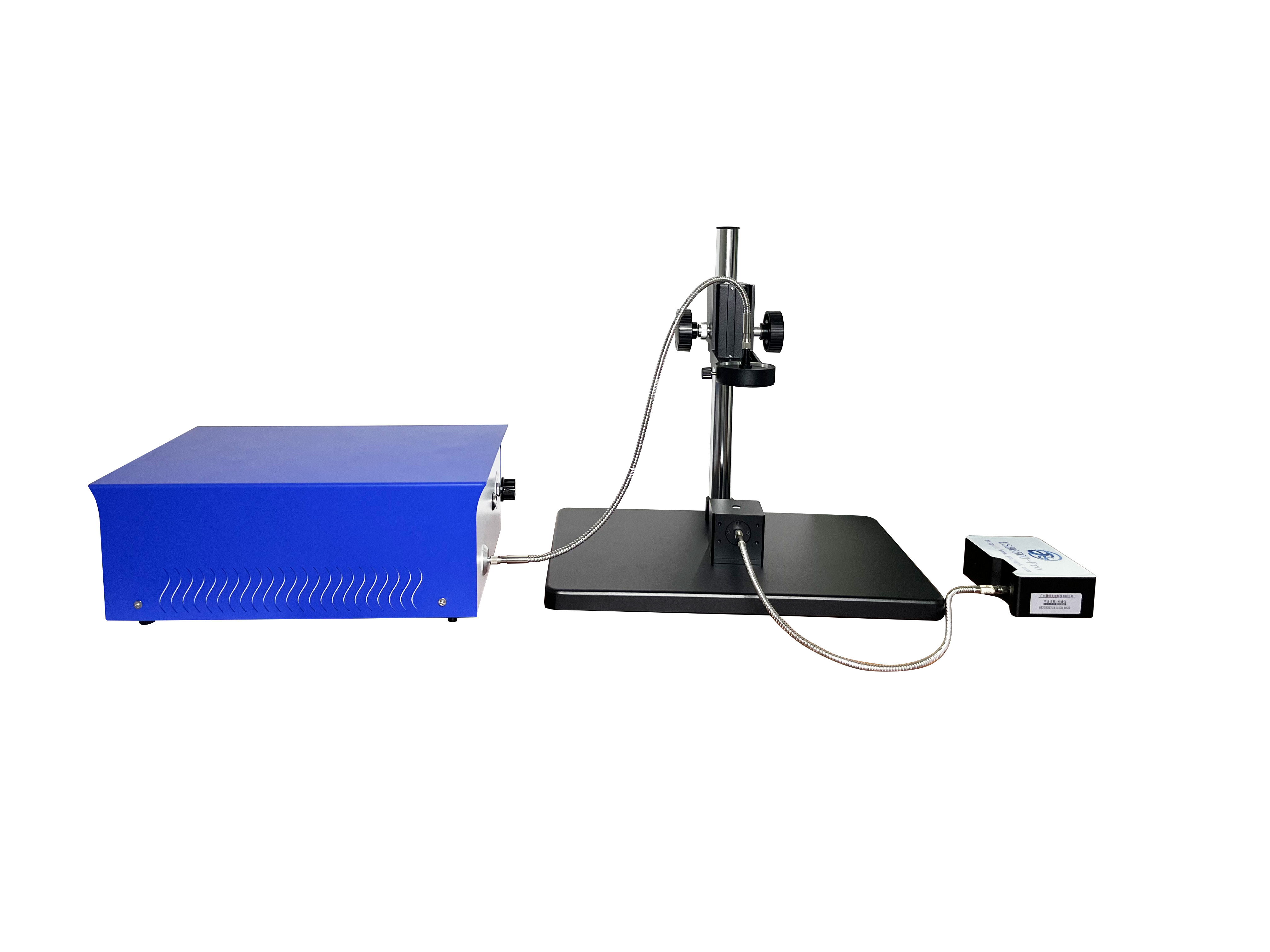
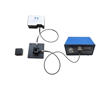
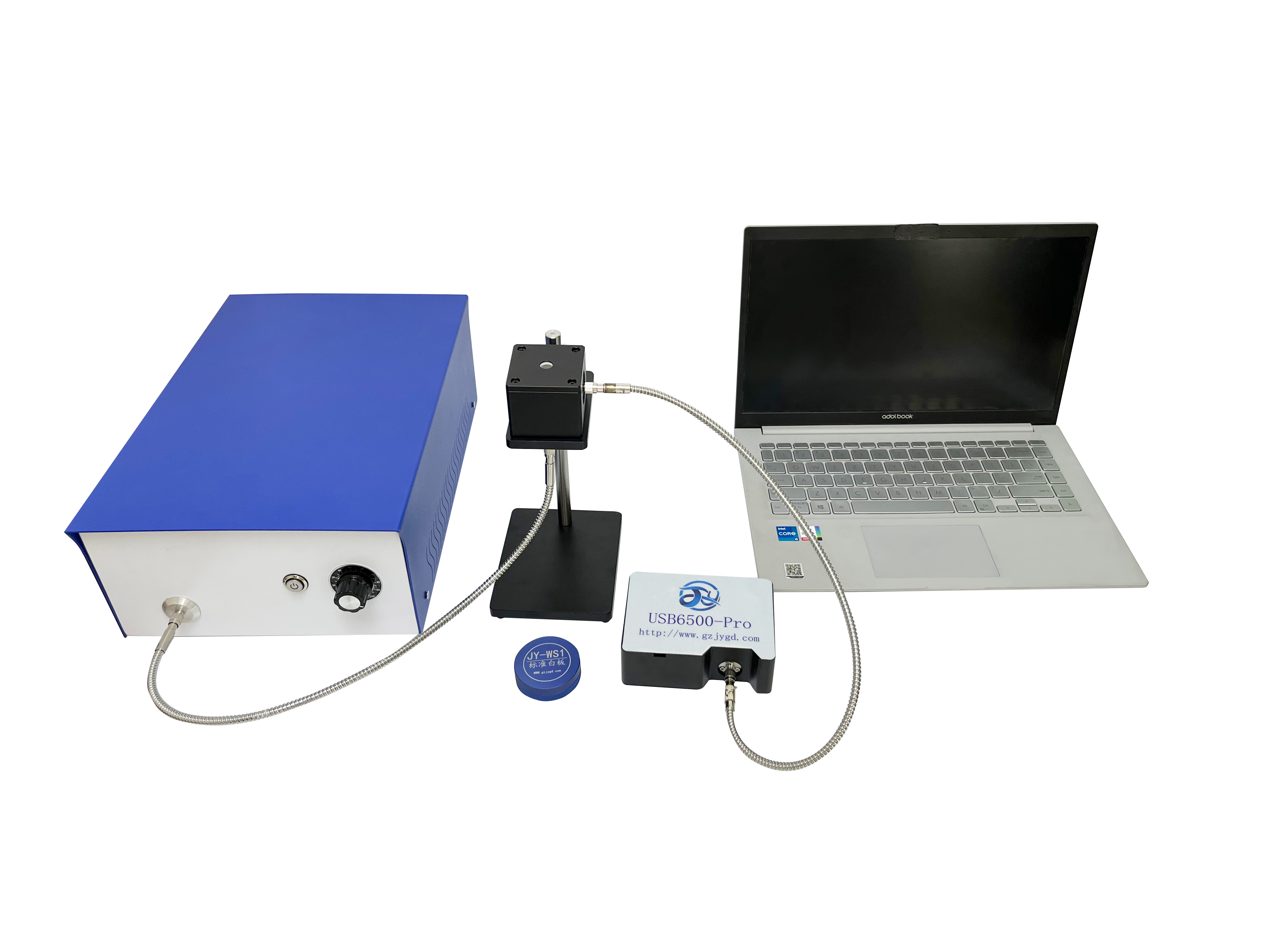
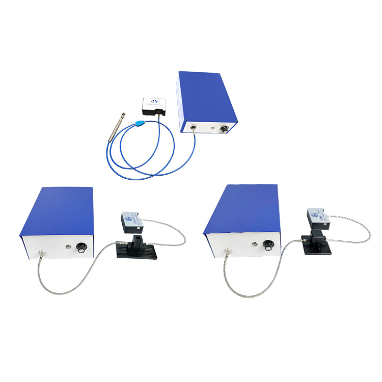
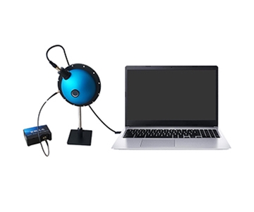
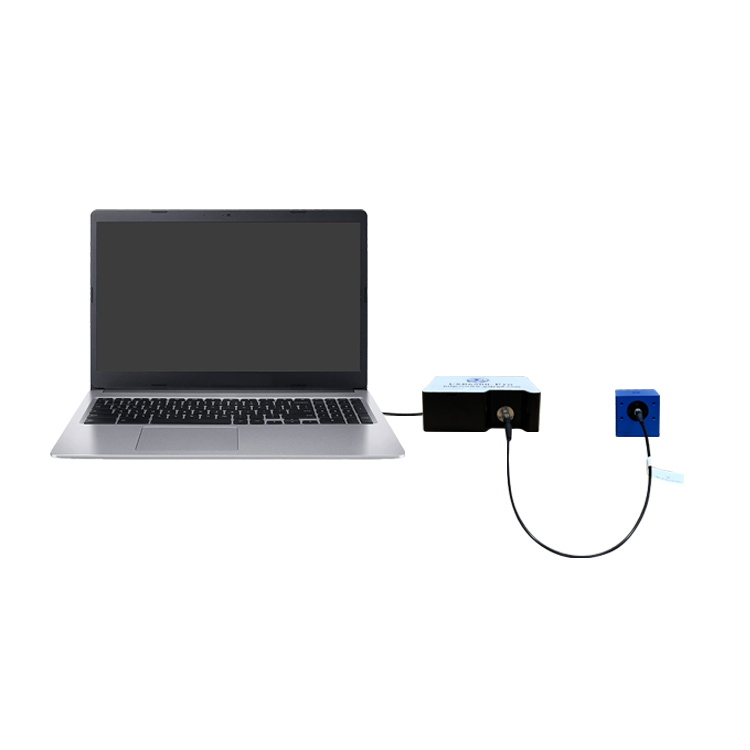
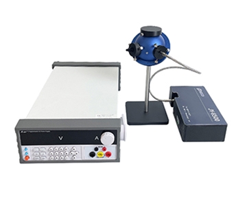
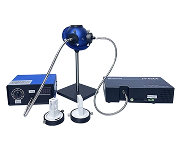
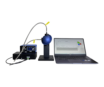
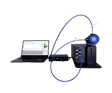
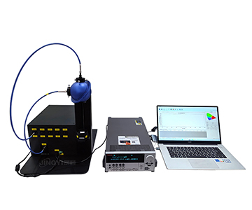
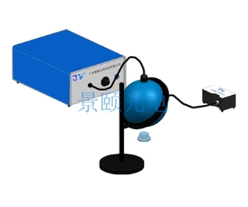
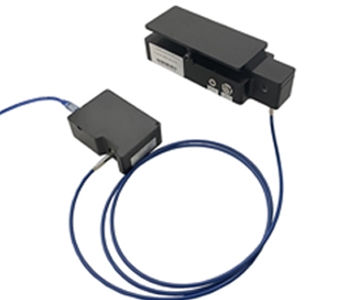
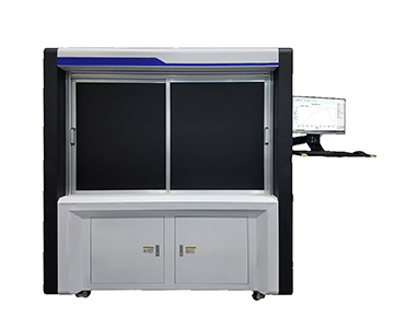
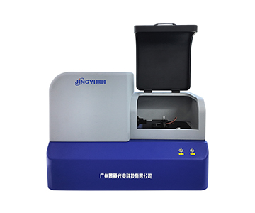
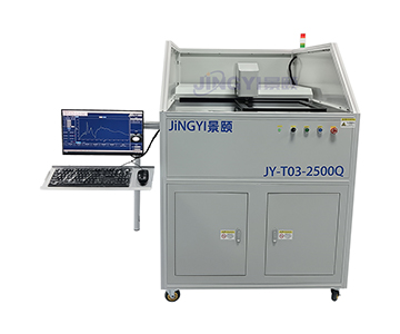
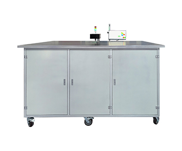
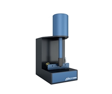
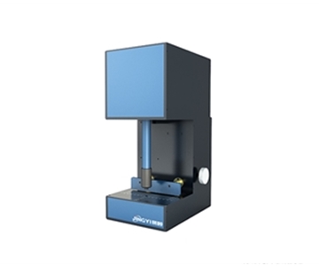
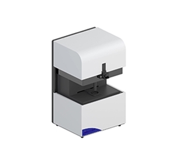
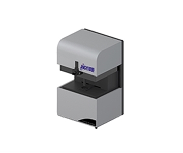
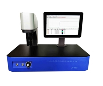
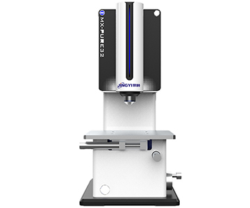
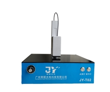
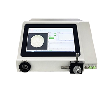
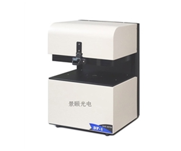
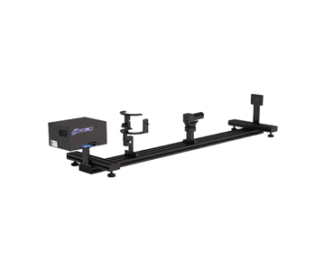
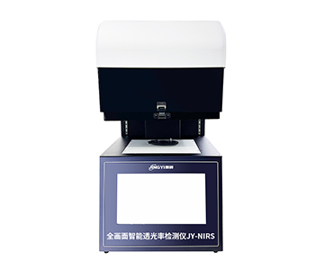
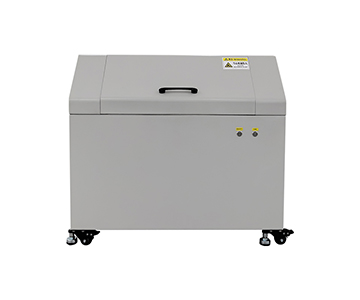
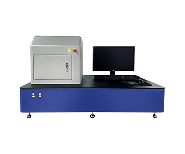
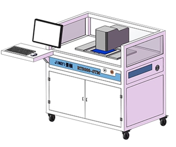
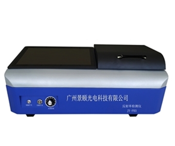
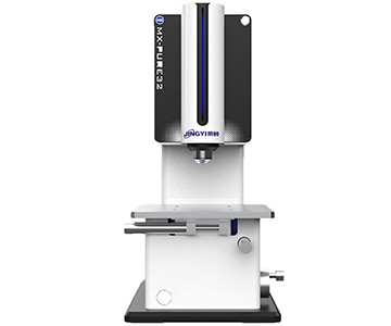
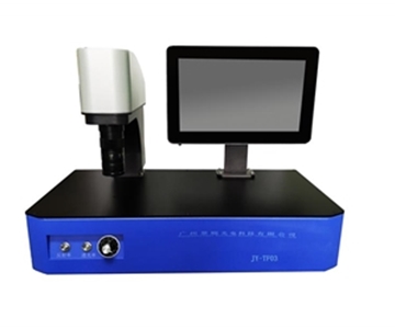
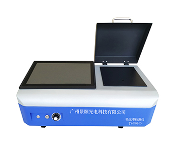
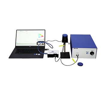
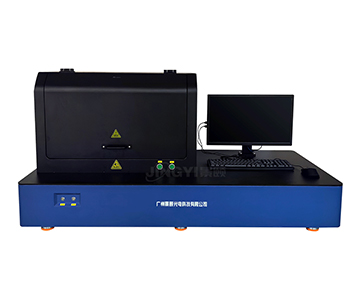
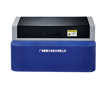
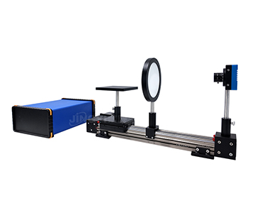
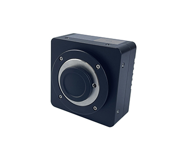
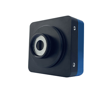
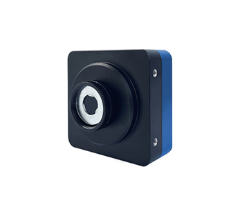
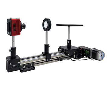
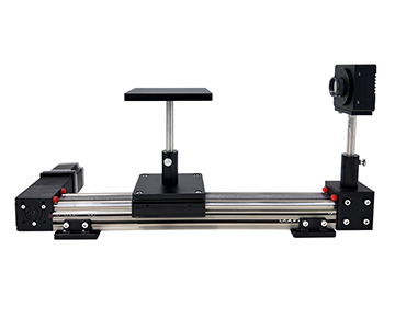
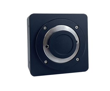
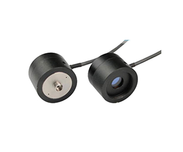
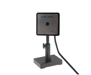
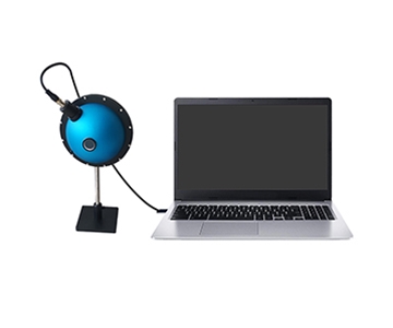
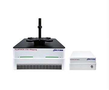
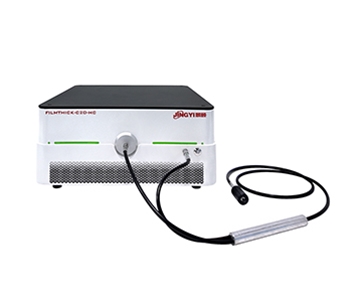
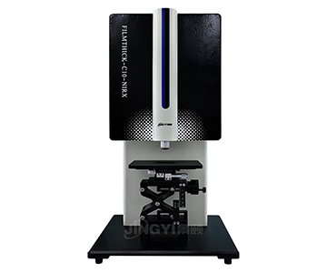
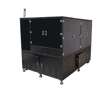
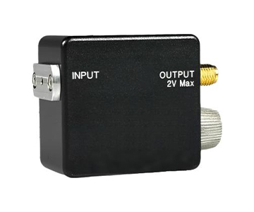
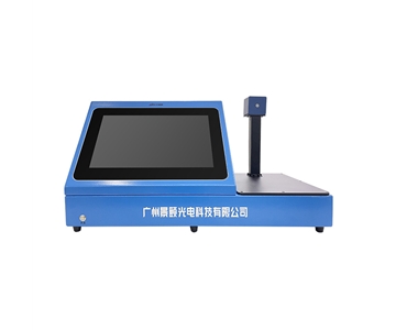
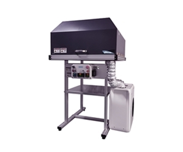
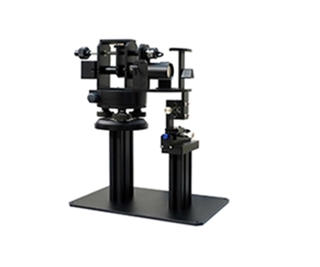
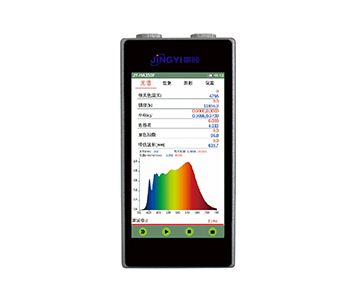
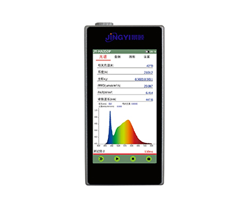
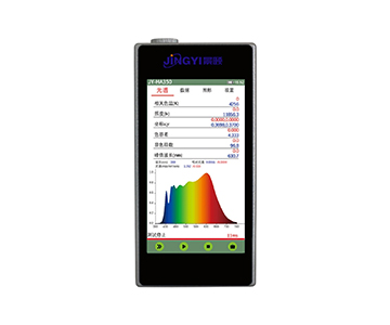
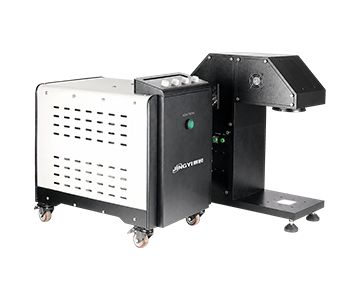
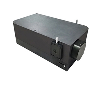
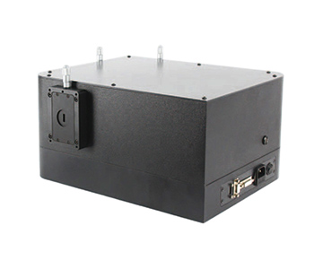
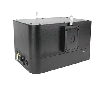
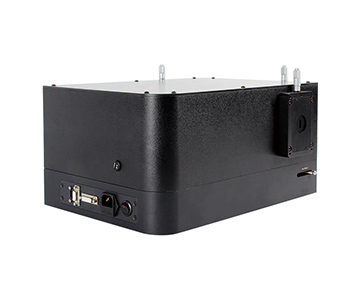
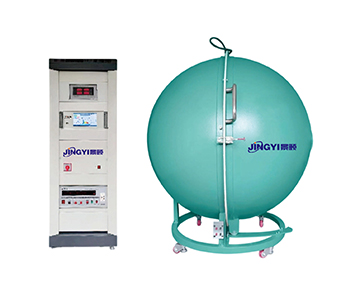
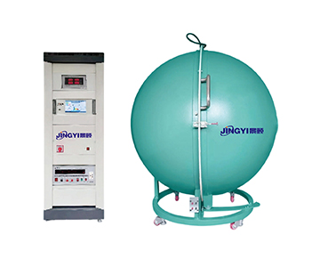
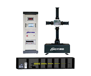
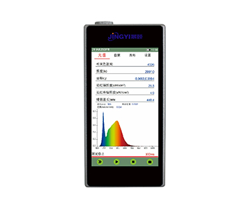
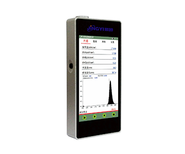
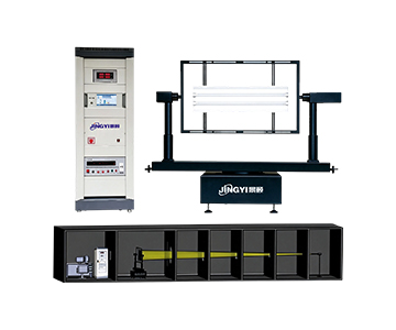
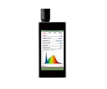
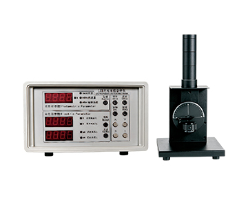
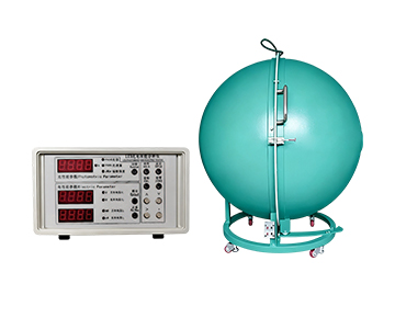
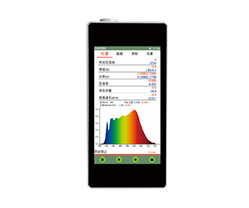
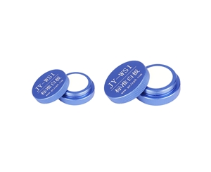
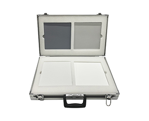
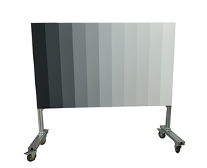
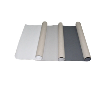
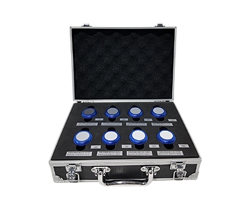
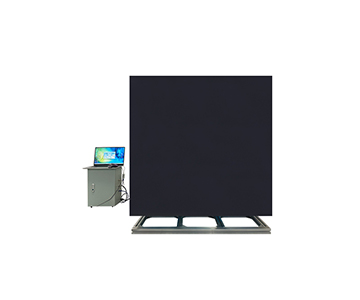
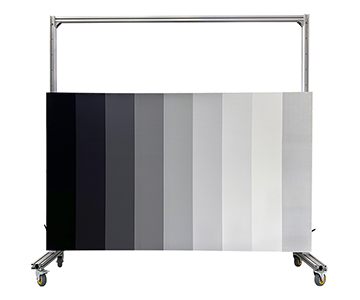
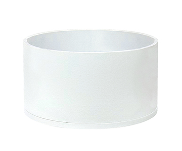
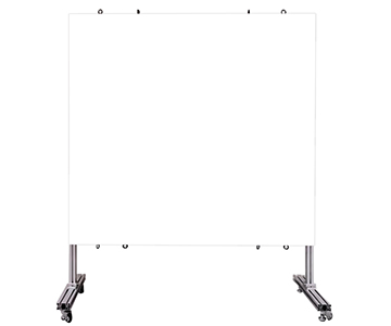
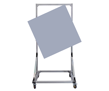
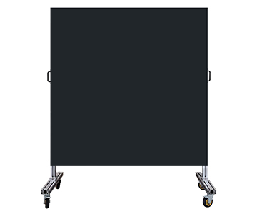
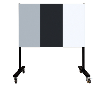
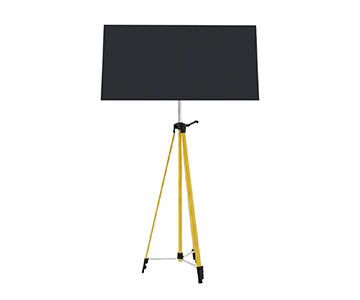
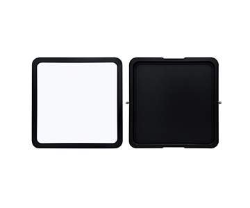
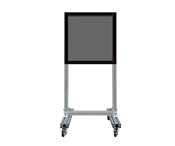
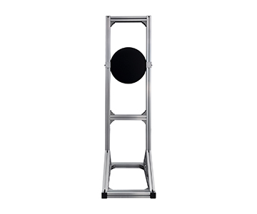
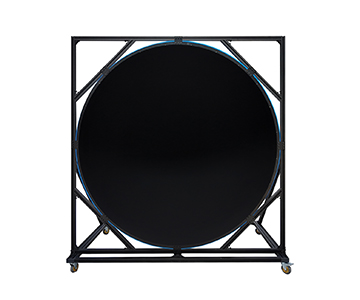
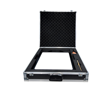
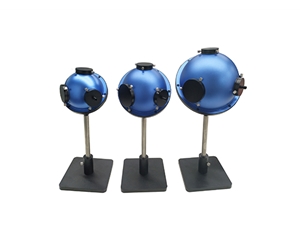
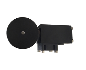
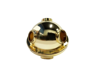
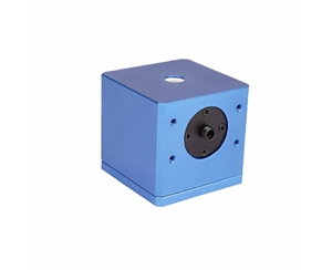
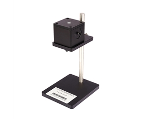
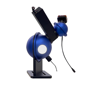
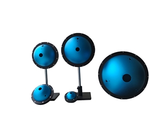
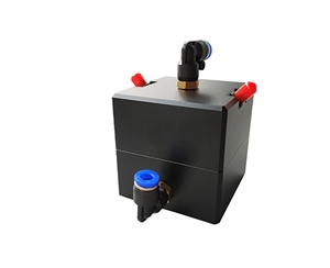
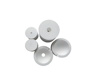
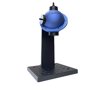
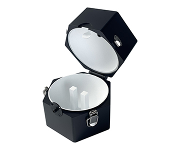
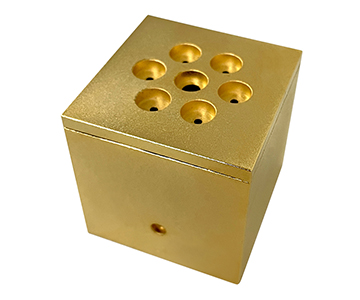
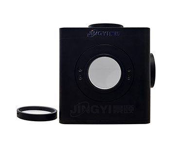
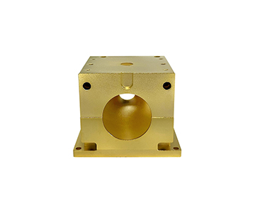
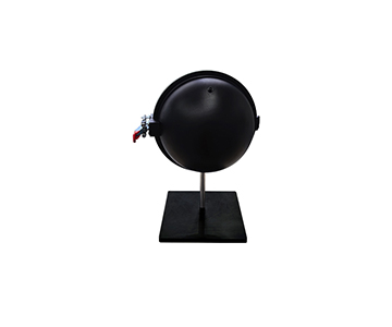
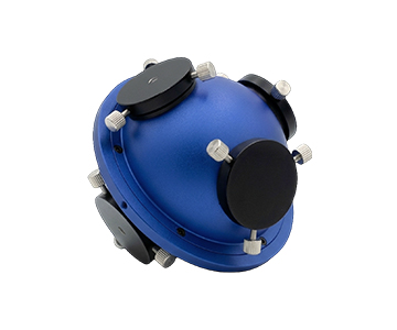
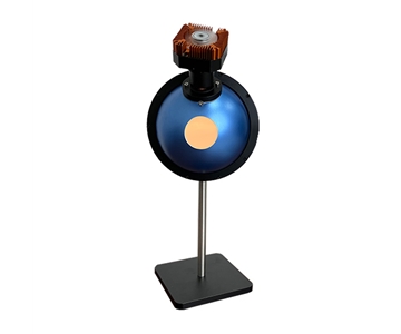
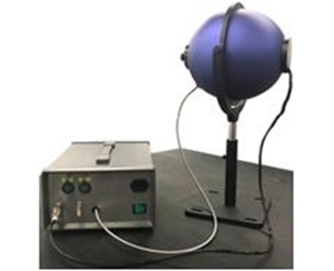
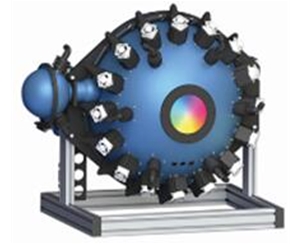
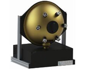
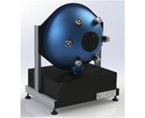
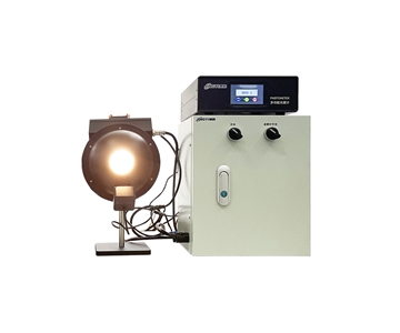
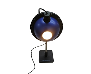
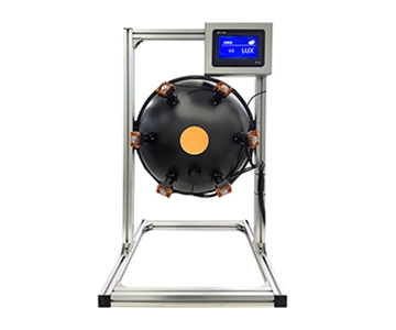
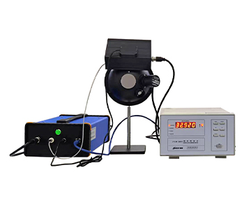
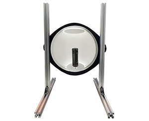
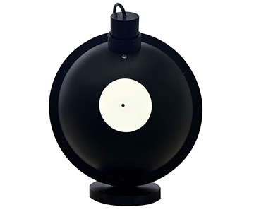
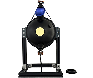
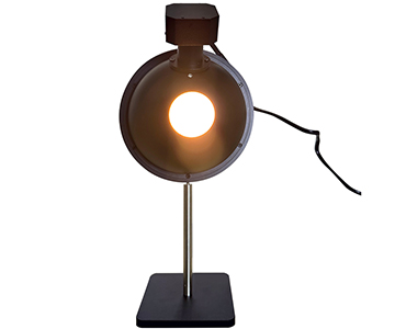
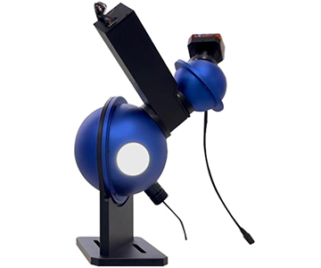
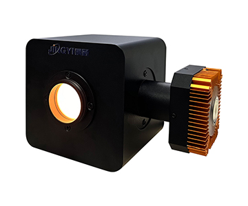
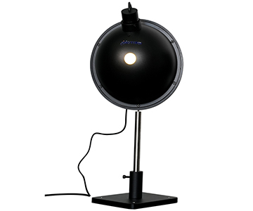
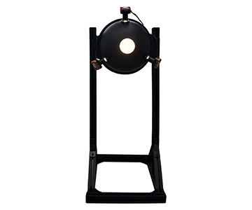
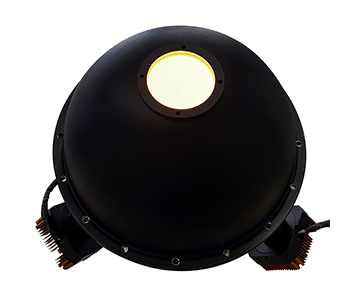
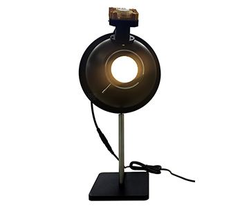
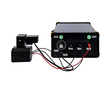
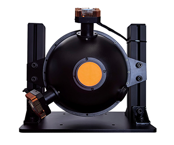
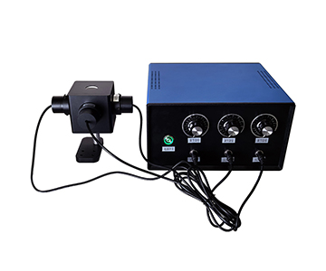
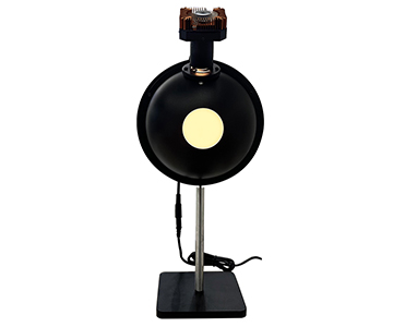
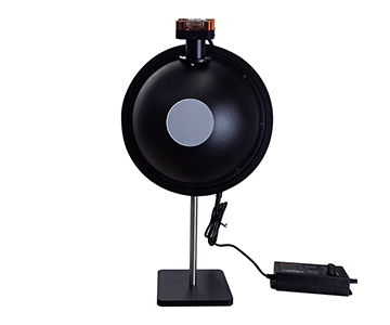
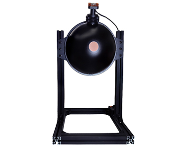
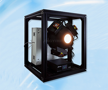
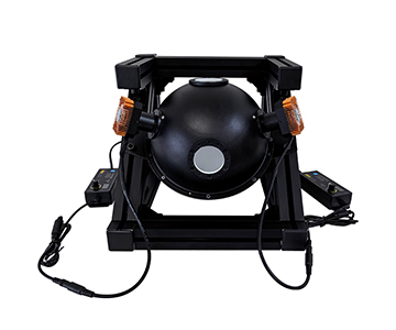
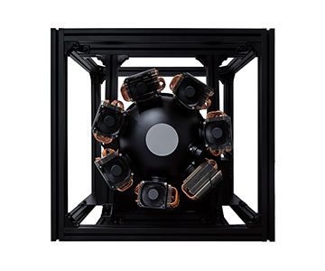
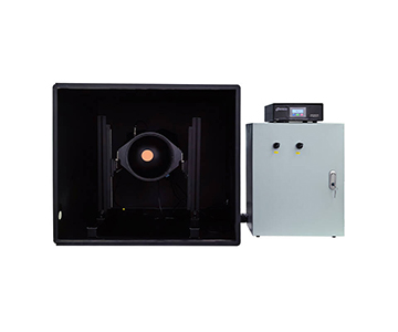
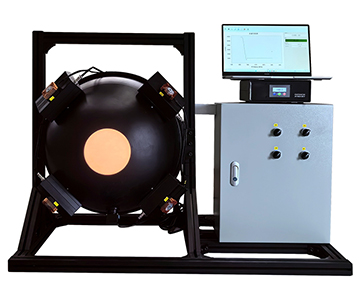
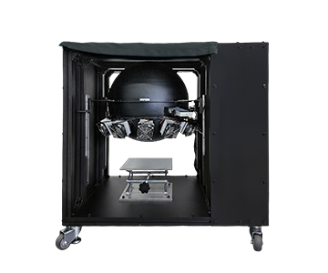
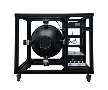
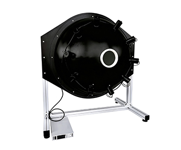
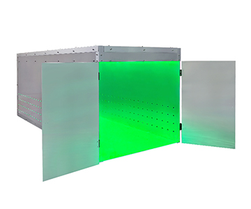
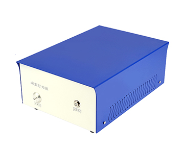
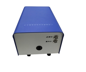
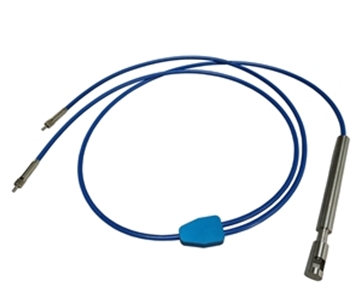
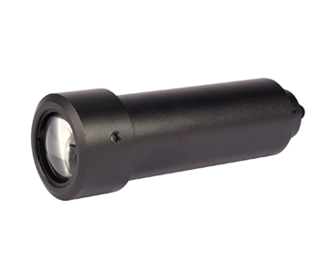
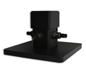
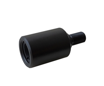
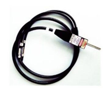
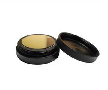
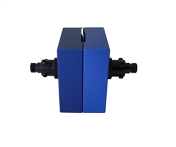
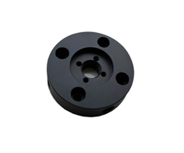
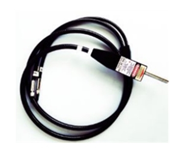
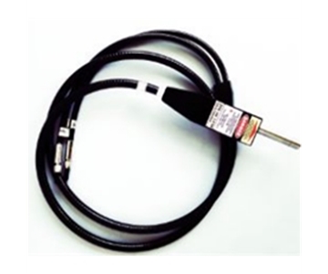
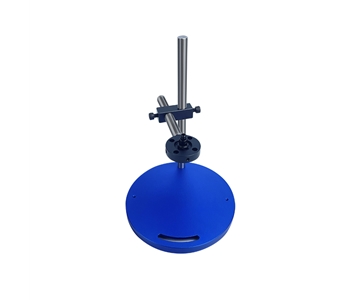
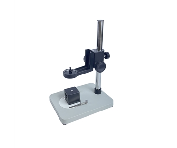
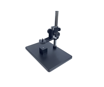
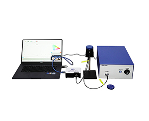
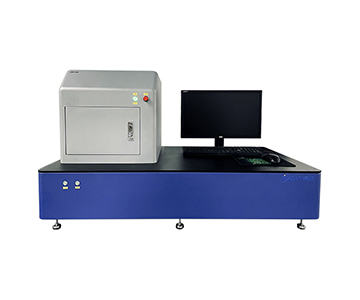
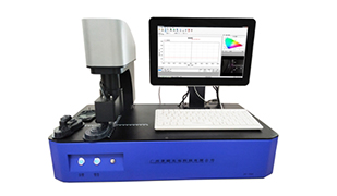
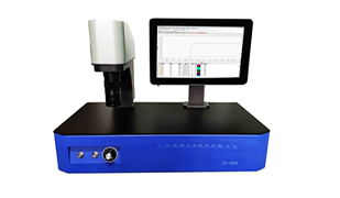
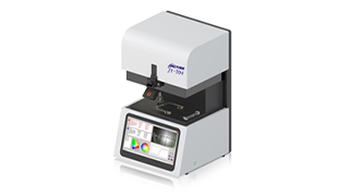
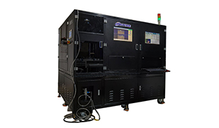
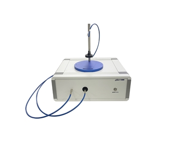
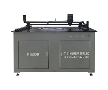
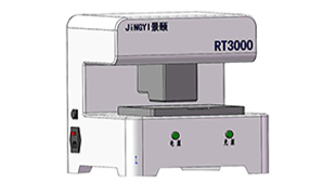
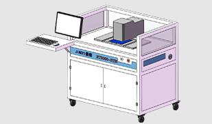
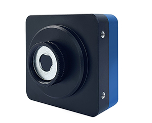
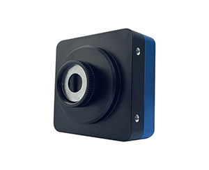
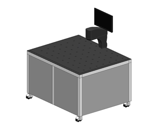
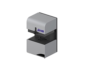
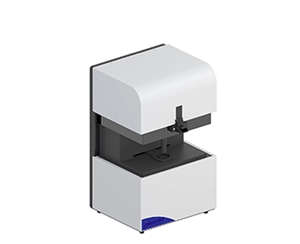
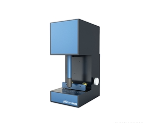
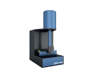
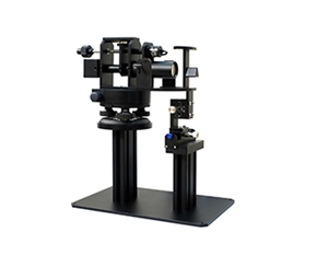
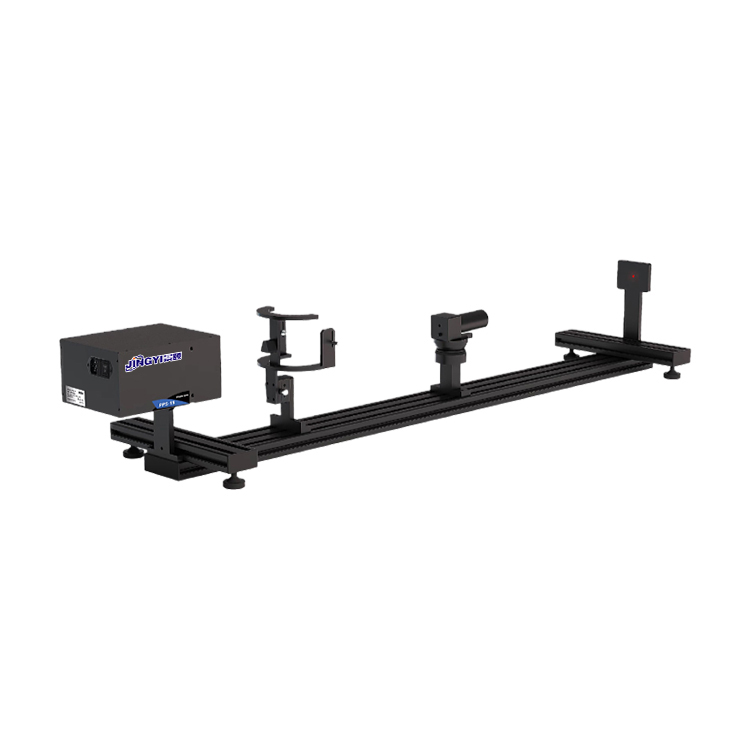
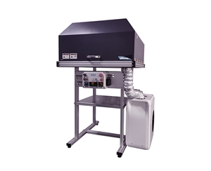
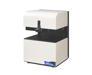
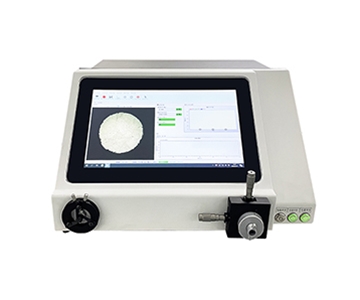
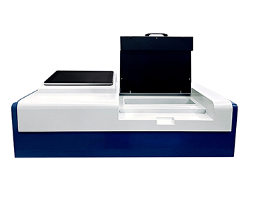
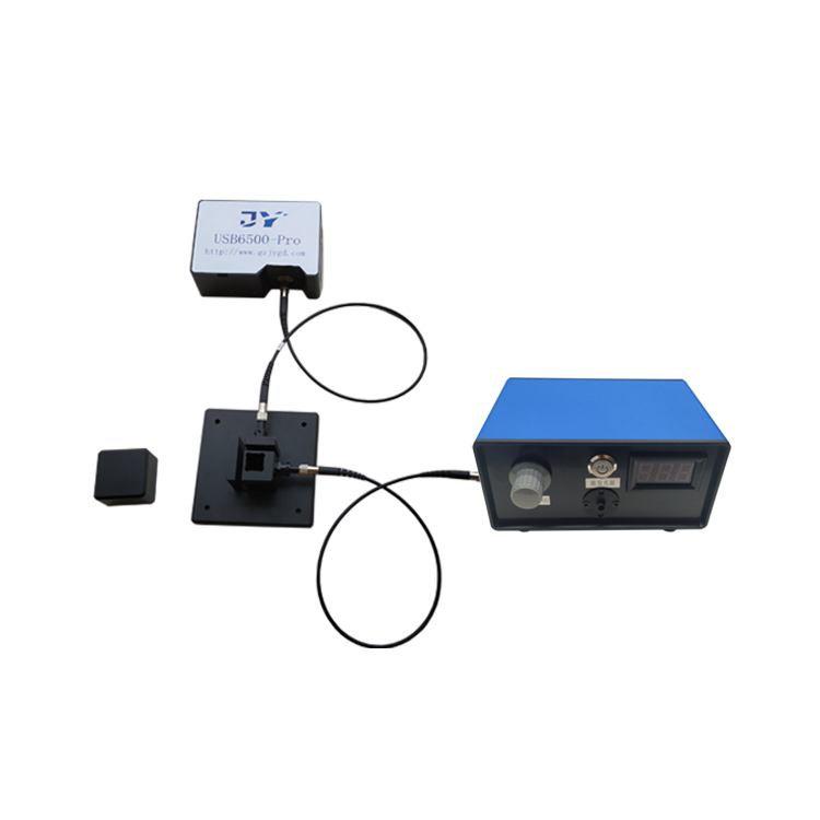
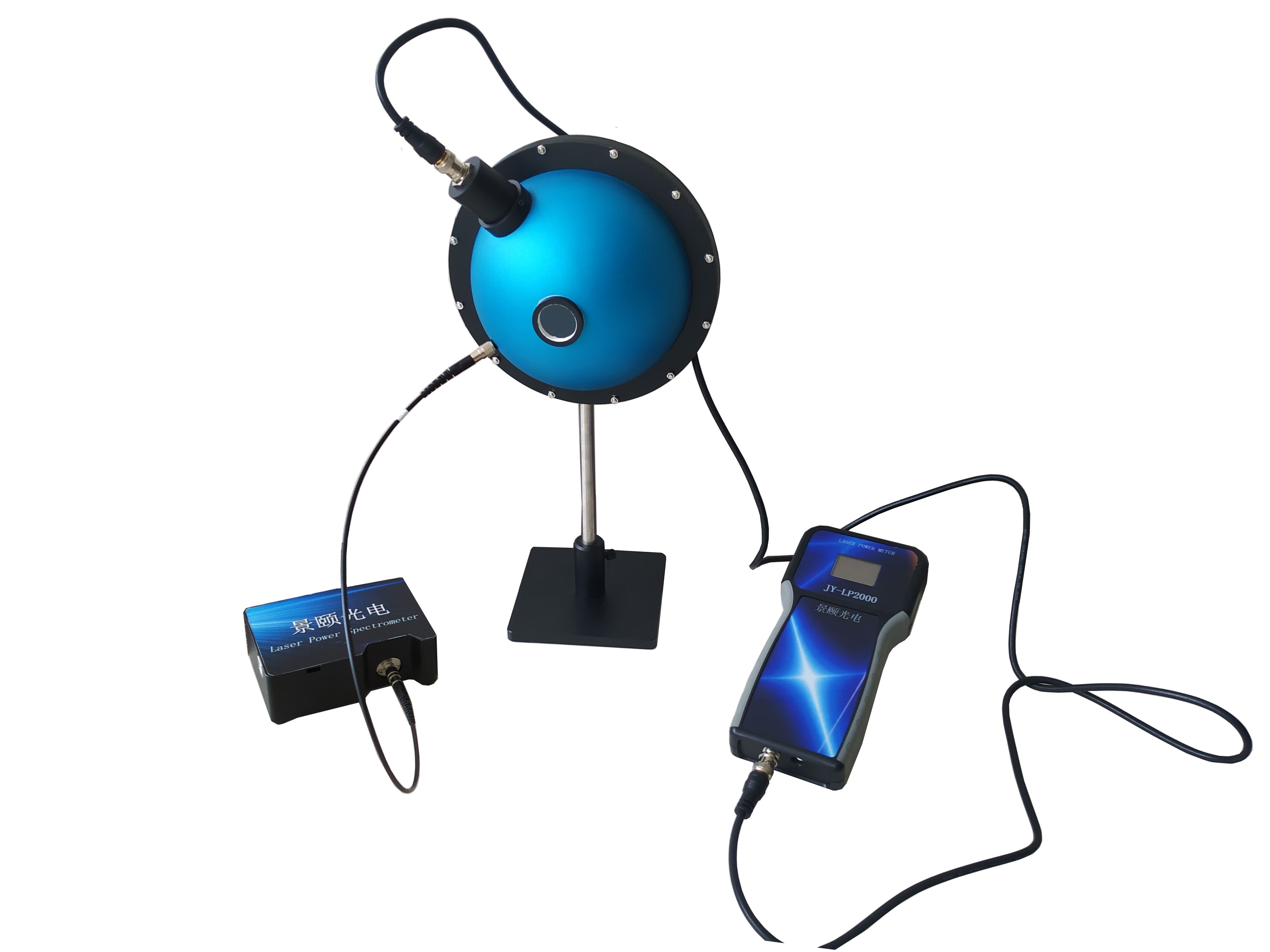
Radiometric calibration of CCD/CMOS sensors, aerospace remote sensing detectors, and low-light imaging systems demands a uniform radiation source with traceable standards. Procurement decisions should prioritize surface uniformity above 98%, spectral coverage from 200 nm to 2500 nm, real-time luminance or illuminance monitoring, and NIST-traceable calibration chains over peak brightness claims. Evaluated systems deliver continuous adjustability from 0.0001 lux to 100,000 lux equivalent levels while meeting international compliance requirements, serving automotive electronics, environmental monitoring, and optical communications industries with reproducible output.
The Hidden Risks Behind Specification Sheets
A three-year maintenance contract for an imported reference-grade integrating sphere often exceeds the purchase price of a domestic mainstream
Three recurring pitfalls dominate the market. Uniformity figures labeled above 99% frequently omit the number of test points and whether edge sampling at the output port was included. Low-price offerings substitute PTFE-coated cavities with ordinary diffusing plates, causing reflectance to collapse in the ultraviolet range. Model confusion arises when illuminance monitoring, luminance monitoring, and spectral monitoring—three distinct detection architectures—are presented interchangeably, leaving buyers with equipment unable to interface with production-line MES systems.
During a late-night reverification at a provincial metrology institute, a detector produced three consecutive readings deviating by 0.37%. The root cause was not the detector but the angular uniformity of the reference source falling short of requirement. When radiometric calibration depends on a source that merely "looks bright enough," the error chain begins at the very first step.
Why Standard Numbers Outweigh Marketing Claims
In certification compliance, adjectives like "high precision" or "excellent uniformity" carry no weight. The credible reference points are standard designations paired with measured data.
Under GB/T 47066-2026, which specifies integrating sphere optical paths and measurement values for total transmittance and reflectance of plastics, the evaluated system employs a PTFE high-diffuse coating with 98% reflectance and a 200–2500 nm spectral range, serving as a reference radiation source for transmittance and reflectance calibration.
Per GB/T 43594-2023 for uniform light sources, calibration-grade units must meet tighter limits on surface non-uniformity, with angular non-uniformity controlled within the 1% range across a ±15° field of view. Writing this requirement into the technical agreement provides far more protection than a supplier's verbal assurance.
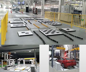
For applications involving automotive cameras or LiDAR receiver calibration, compliance with T/CITS 231-2025 automotive LiDAR technical requirements ensures measurement traceability. Spectral matching and angular uniformity must rest on documented standards rather than empirical estimates.
Seven Procurement Dimensions Decoded
Uniformity: Separate Surface from Angular Metrics
Base-model devices achieve surface uniformity above 98%, while larger sphere diameters push beyond 99%. Asking only about surface uniformity is insufficient; angular uniformity must be queried independently. For aerospace remote sensing calibration, angular uniformity within a ±15° field directly determines calibration error at a detector's edge pixels.
Spectral Coverage: The 50 nm Gap That Breaks Deep-UV Traceability
PTFE-coated cavities typically span 200–2500 nm, though some models start at 250 nm. When calibrating deep-UV detectors or deuterium lamp chains, that missing 50 nm compromises short-wavelength traceability integrity.
Luminance and Illuminance Dynamic Range
Luminance-monitored units cover 0.01 to 100,000 cd/m² equivalent, while low-light illuminance models reach 0.0001 lux. Dual-sphere architectures extend further to 1×10⁻⁷ lux for starlight and moonlight simulation. Procurement must verify high-brightness linearity and low-light step resolution as two independent criteria.
Adjustment Method: Motorized Irises as a Production Imperative
Manual adjustment introduces replication errors during product changeovers. Evaluated configurations feature four motorized irises with 1 K color temperature resolution across a 2000–20,000 K range. Ethernet communication—with USB available on select models—is the prerequisite for automated production-line integration.
Coating Process and Reflectance
PTFE spray coatings reach 98% reflectance; barium sulfate
Sphere Diameter and Output Port Matching
Sphere diameters range from 150 mm to 1500 mm, with output ports customizable from 5 mm to 500 mm. A practical boundary: the output port should not exceed one-third of the sphere diameter, or edge uniformity degrades. Large-aperture remote sensing calibration demands spheres in the 1000 mm class; small-field low-light devices are more economically served by 150 mm spheres paired with 5–50 mm ports.
Monitoring Type: Choose the Correct Architecture
Luminance monitoring, illuminance monitoring, spectral monitoring, color temperature monitoring, and spectral irradiance monitoring represent five distinct technical paths. CCD camera calibration favors luminance monitoring; fluorescence measurement systems require spectral monitoring; white LED panel testing depends on color temperature and CRI linkage.
Horizontal Comparison by Price Tier
| Tier |
Sphere / Output Port |
Uniformity |
Light Source |
Monitoring |
Application Boundary |
| $200K+ Import Reference |
Custom large diameter |
Claim high; third-party reverification needed |
Halogen / deuterium-halogen |
Mature software ecosystem |
Ample budget; requires OEM traceability |
| $50K–$100K Domestic Mainstream |
300–500 mm / 100–150 mm |
>98% to >99% |
Multi-lamp redundancy + 4 motorized irises |
Luminance / illuminance / spectral optional |
Lab R&D and production line |
| <$50K Domestic Economy |
150–200 mm / 5–50 mm |
>98% |
Single / dual halogen |
Primarily illuminance |
Small-field devices; educational calibration |
Beyond the table, two figures carry more procurement weight than any "high brightness" claim. Mainstream domestic units achieve 1 K color temperature steps and 0.01 lux resolution across the 0.01–100,000 luminance range. Dual-sphere low-light configurations push illuminance down to 1×10⁻⁷ lux while holding uniformity above 99%.
For international benchmarking, StellarNet offers a mature miniature spectrometer ecosystem with strong portability, but integrating sphere sources are not its core product line, resulting in extended repair cycles. BaySpec has accumulated expertise in hyperspectral imaging, yet its domestic service network remains limited. Both serve as technical references rather than direct production-line replacements.
Four-Step POC Verification Protocol
Nine-point sampling. Arrange a photometer in a 3×3 grid across the output port, record illuminance at each point, calculate surface non-uniformity, and compare against calibration-grade limits from GB/T 43594-2023.
Angular scanning. Repeat sampling at ±15° and ±30° viewing angles to confirm angular uniformity stays within the 1% threshold.
Low-light linearity. Step down from 1000 lux to 0.001 lux in increments, recording deviation between actual and set values at each level, with close attention to step discontinuities in the low range.
Thermal equilibrium retest. After two hours at full power, repeat the nine-point sampling to observe uniformity shift caused by coating thermal drift.
Pre-Procurement Checklist: Ten Questions
1.Are measured values provided separately for surface uniformity and angular uniformity?
2.Does the test point count reach at least nine, with test distance specified?
3.Is the coating material PTFE or an ordinary diffusing plate?
4.Does the spectral range fully cover the detector under test?
5.How many motorized irises are included, and is communication via Ethernet or manual only?
6.Are raw records available for resolution and repeatability below 1 lux?
7.Will third-party test reports or original self-test curves be supplied?
8.Is standards compliance—such as GB/T 47066-2026—written into the technical agreement?
9.Are warranty terms and consumable lamp costs itemized separately?
10.Are software upgrades and MES integration subject to additional fees?
Three Common Engineering Mistakes
Brightness-peak fixation. A unit rated at 100,000 lux loses linearity below 1 lux, amplifying night-vision calibration errors into double-digit percentages.
Ignoring output port to detector entrance pupil matching. When the output port is smaller than 1.5 times the entrance pupil, edge field illuminance drops and the entire calibration curve shifts.
Confusing monitoring with closed-loop control. Illuminance monitoring observes without correcting; luminance feedback closed-loop actively stabilizes output. Continuous production-line operation demands the latter.
Application Boundaries and Honest Limitations
Integrating sphere sources are not universal reference standards. Under sustained high-power halogen irradiation, PTFE coatings face thermal aging limits. When internal temperatures approach the 80°C ceiling, reflectance and uniformity drift gradually over operating hours, necessitating scheduled factory recalibration.
Structurally, single-sphere designs experience diminishing uniformity returns once the output port exceeds one-third of the sphere diameter. Ultra-large apertures above 500 mm for remote sensing calibration typically require dual-sphere coupling. For 24/7 production environments, both constraints must appear in acceptance attachments rather than becoming post-sale disputes.
Frequently Asked Questions
Q1: How can I quickly verify whether a uniformity claim is credible?
Request the manufacturer's raw nine-point test data with test distance specified, not merely a percentage figure. Calibration-grade equipment should correspond to the calibration-class limits in GB/T 43594-2023.
Q2: Should I choose a single-sphere or dual-sphere design for low-light applications?
For illuminance requirements above 0.0001 lux, a single-sphere low-light model suffices. To simulate starlight-level 1×10⁻⁷ lux, a dual integrating sphere architecture is preferred, making it easier to maintain uniformity above 99%.
Q3: How do I decide between LED and halogen light sources?
Halogen provides continuous spectral output covering the near-infrared, suitable for absolute radiometric calibration of CCD and CMOS sensors. LED offers concentrated color temperature with lower thermal load, better suited for fluorescence and biological low-light imaging.
Q4: Where does total cost of ownership differ between domestic and imported options?
The gap lies in maintenance cycles and consumable pricing. A three-year maintenance contract for imported equipment often exceeds the cost of a domestic host unit. Domestic mainstream models already cover production requirements through lamp redundancy, motorized irises, and Ethernet communication.
Q5: How can I independently verify compliance after delivery?
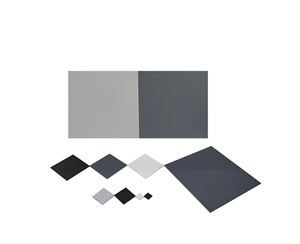
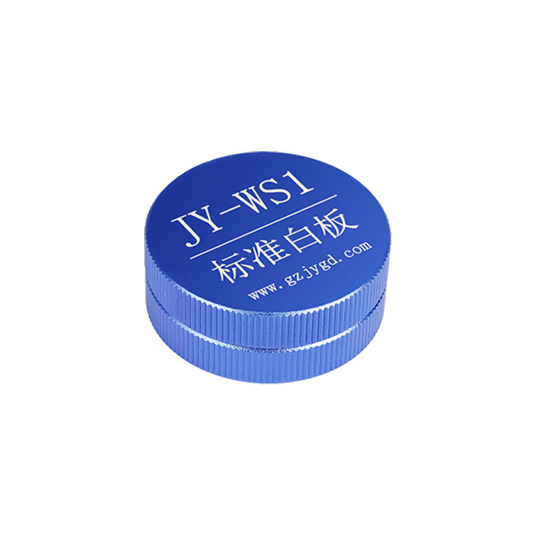
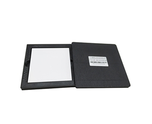
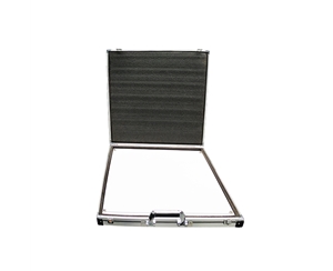
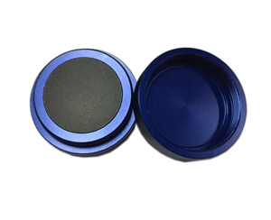
Cross-compare using a standard white reference panel and a NIST-traceable photometer. Re-run the four-step protocol from the verification section above, and include surface uniformity, angular uniformity, and low-light linearity in the acceptance report.
About This Guide
Data Sources
: Uploaded product technical documentation, GB/T 43594-2023
General Specification for Uniform Light Sources
, GB/T 47066-2026
Determination of Total Transmittance and Total Reflectance of Plastics
, in-house validation datasets.
Author
: Cai Xiaodong, Senior Application Engineer, Jingyi Optoelectronics — 12 years in optical inspection and radiometric calibration equipment.
Disclosure
: Jingyi Optoelectronics manufactures integrating sphere uniform light sources. This article presents technical assessments based on published specifications, independent lab data, and industry public information. No compensation was received from third-party brands mentioned.
Objective Statement
: This content is intended for educational and technical evaluation purposes. Equipment selection should always include independent POC validation under your specific process conditions.
Last Updated
: November 2026
For detailed specifications and application notes on integrating sphere uniform light sources, search "Jingyi Optoelectronics + integrating sphere uniform light source" or visit our technical library.