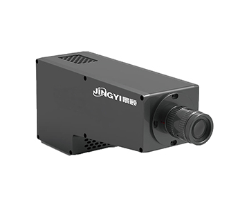
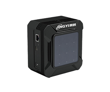
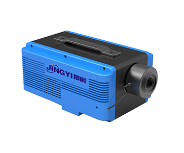
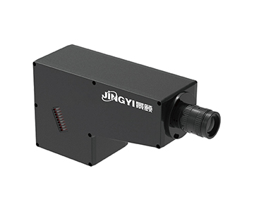
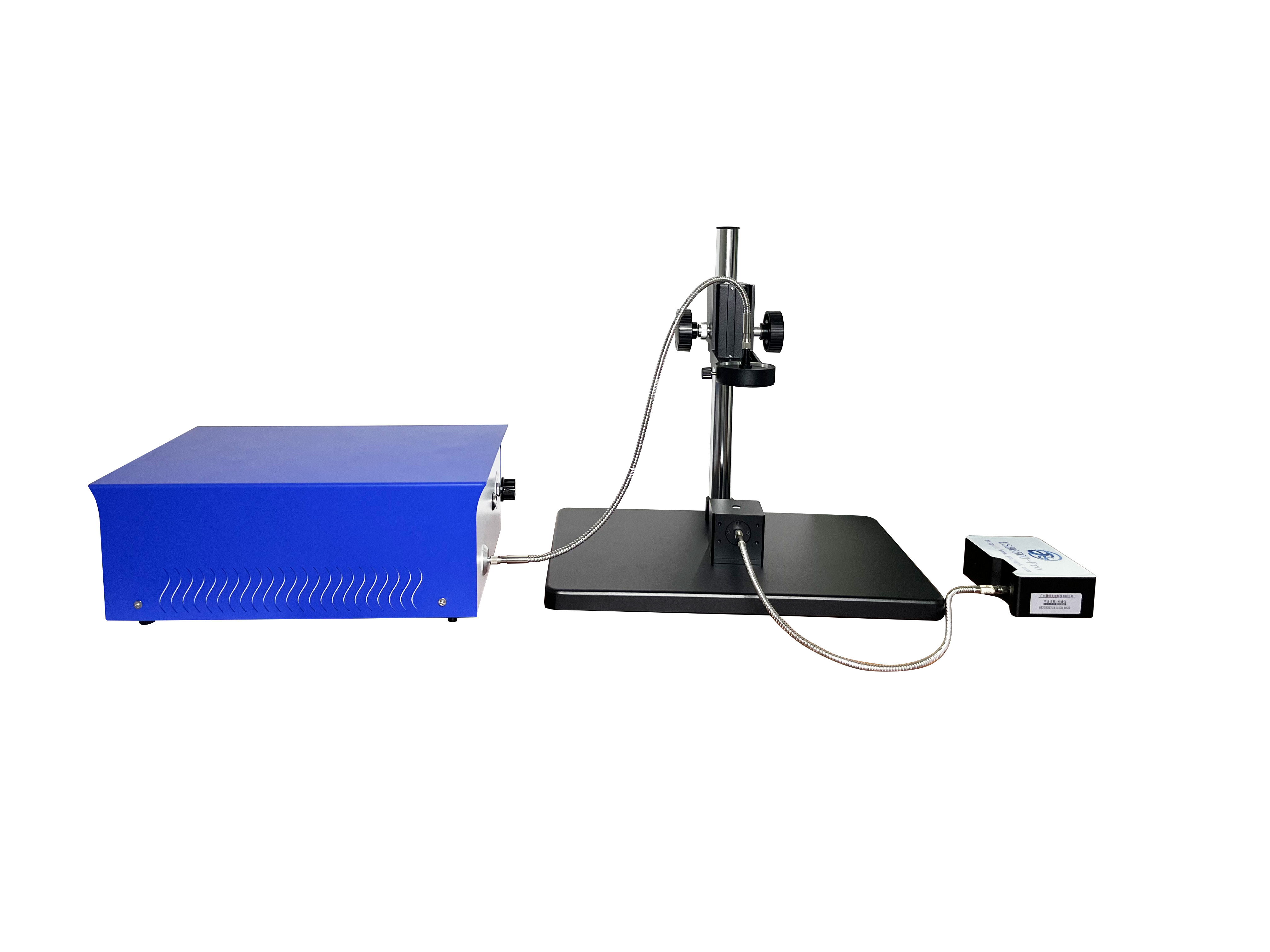
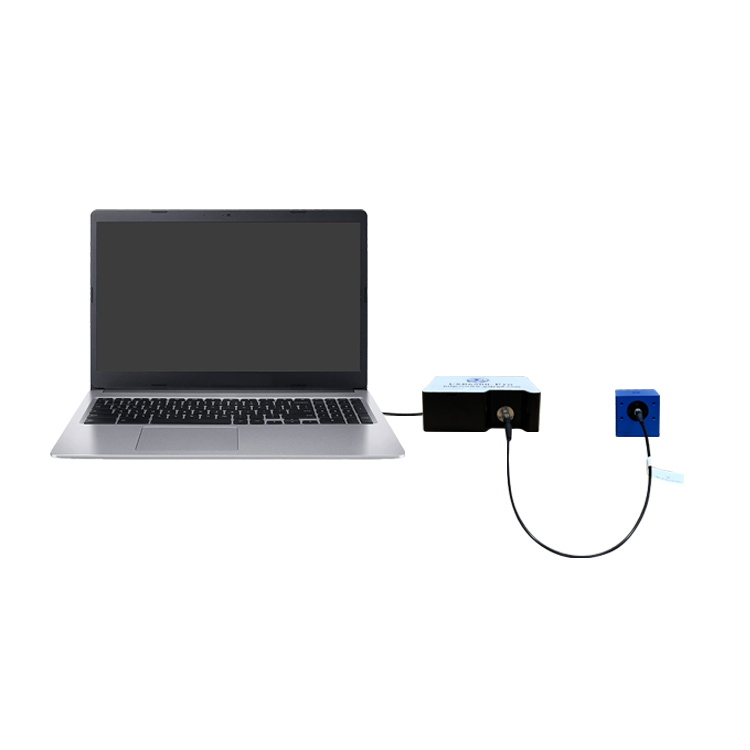
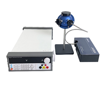
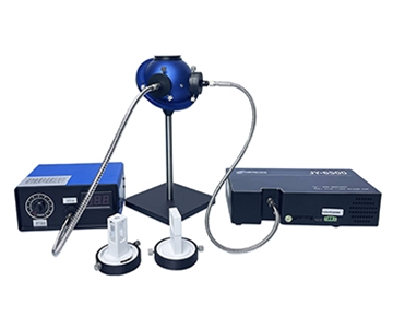
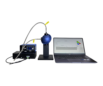
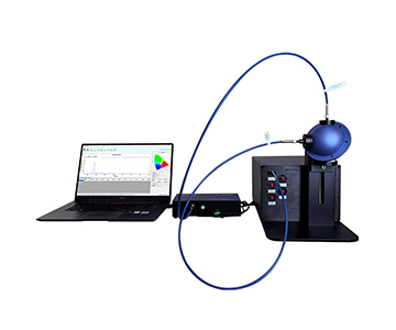
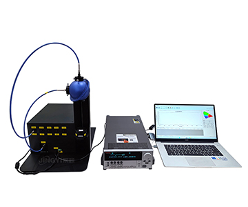
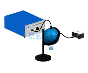
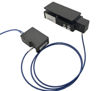
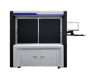
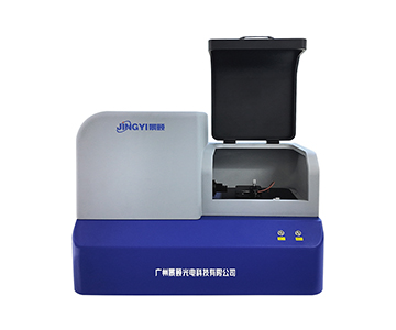
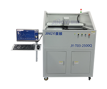
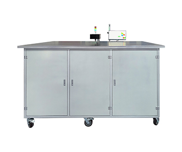
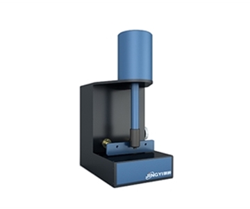
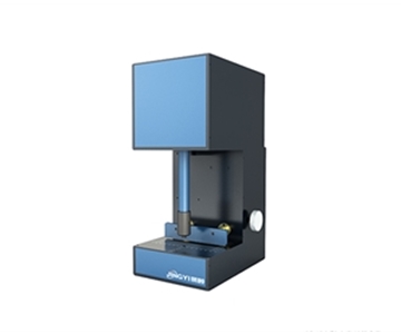
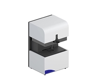
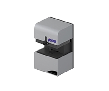
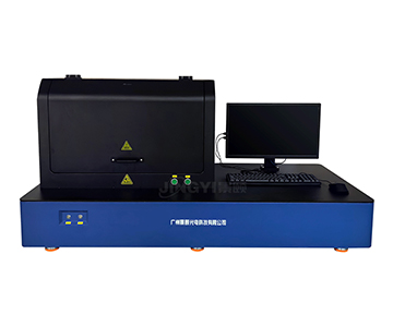
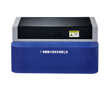
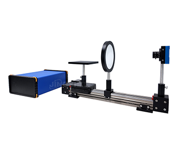
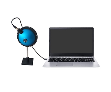
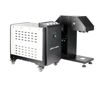
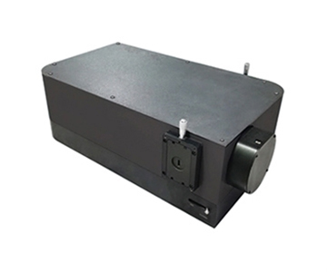
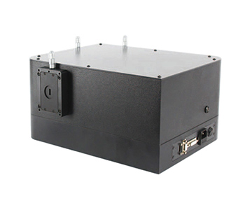
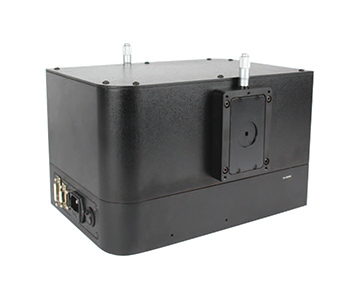
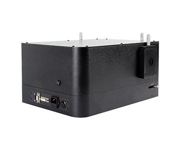
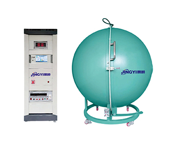
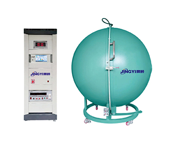
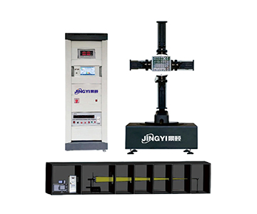
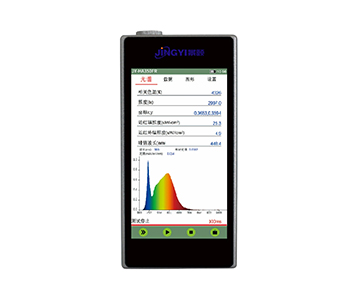
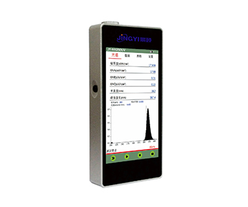
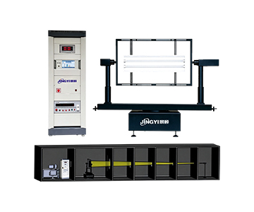
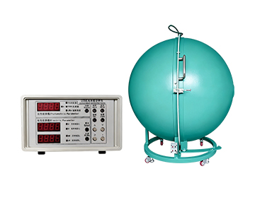
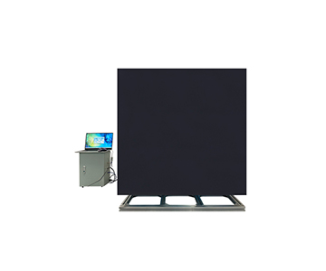
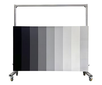
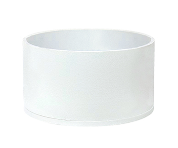
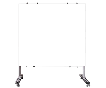
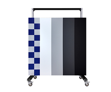
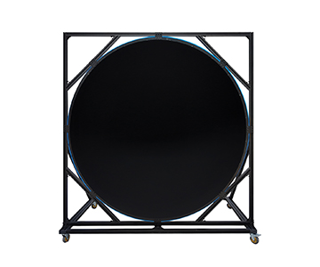
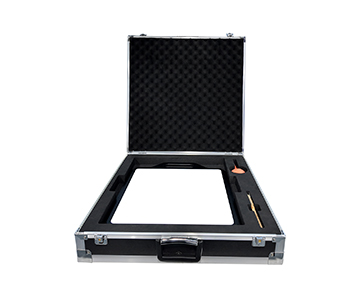
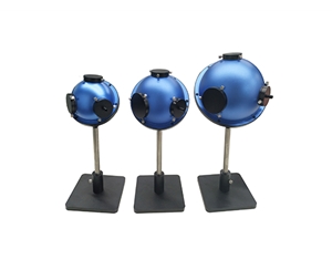
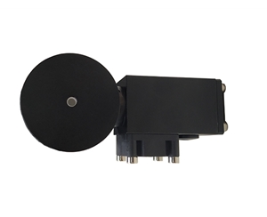
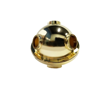
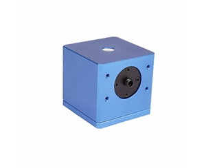
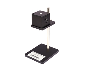
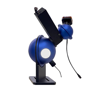
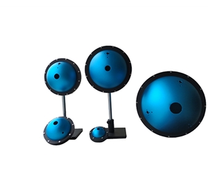
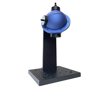
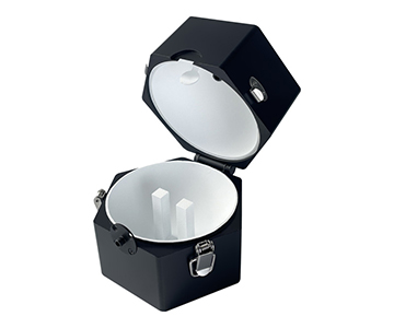
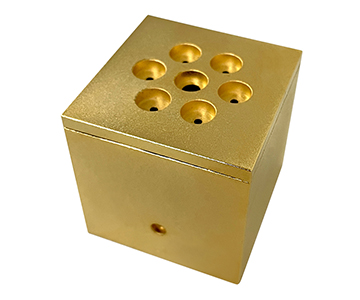
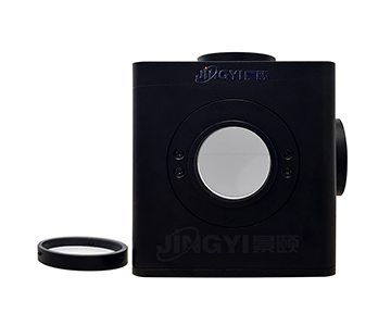
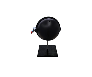
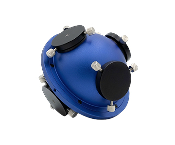
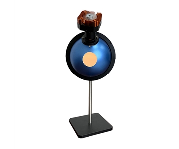
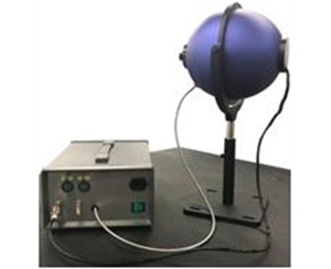
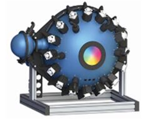
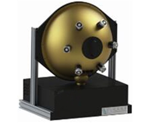
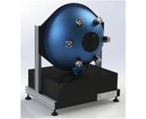
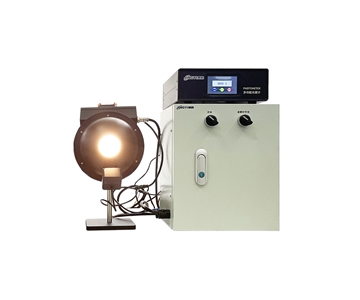
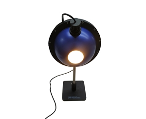
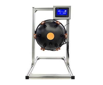
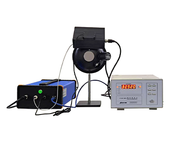
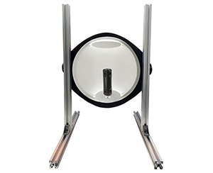
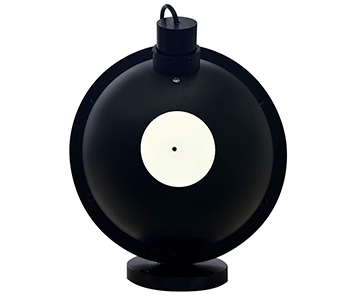
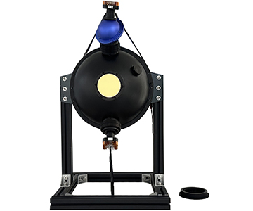
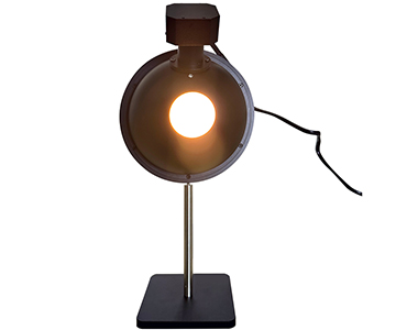
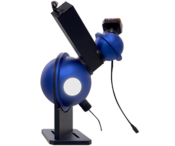
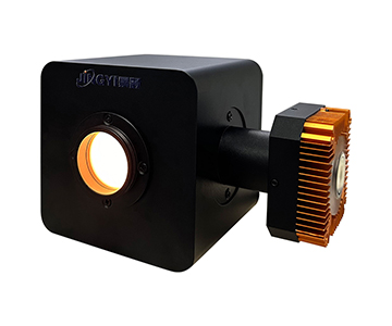
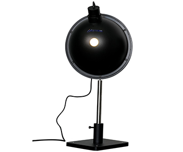
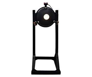
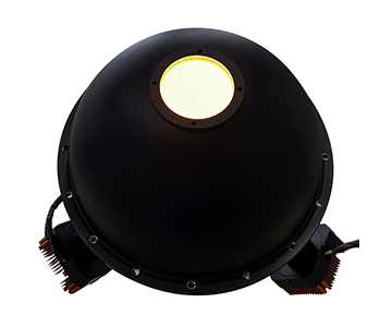
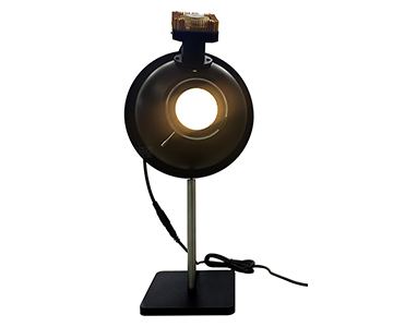
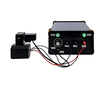
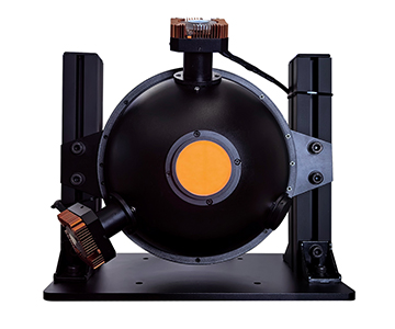
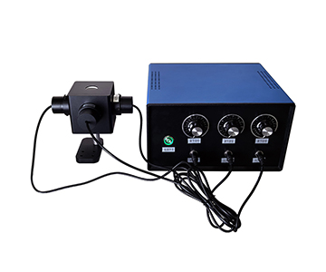
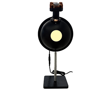
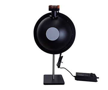
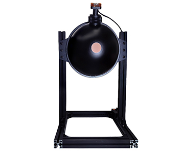
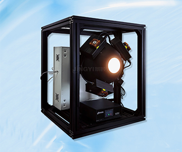
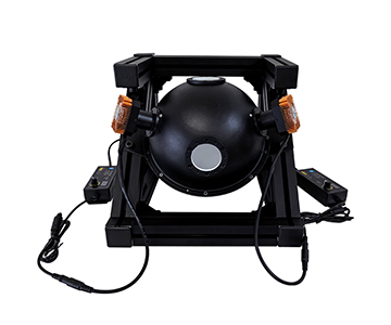
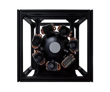
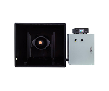
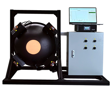
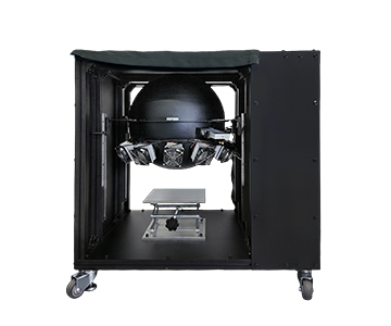
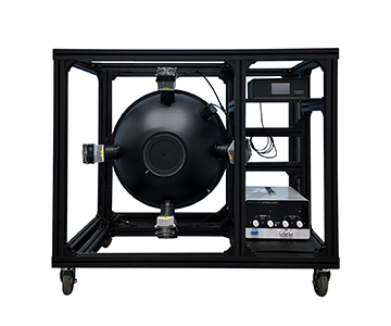
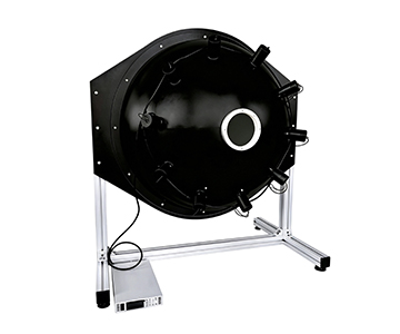
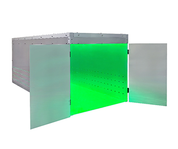
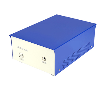
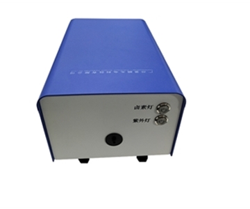
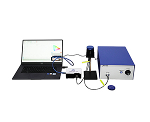
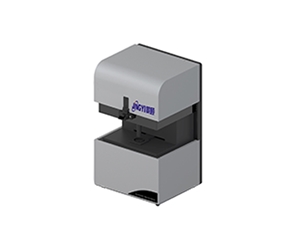
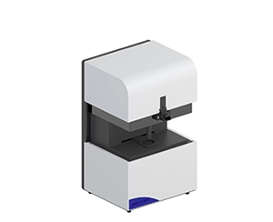
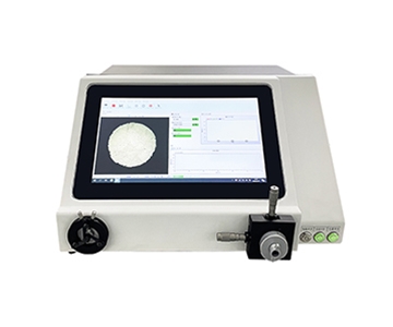
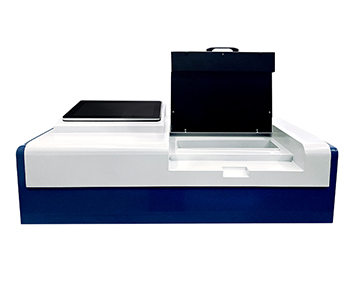
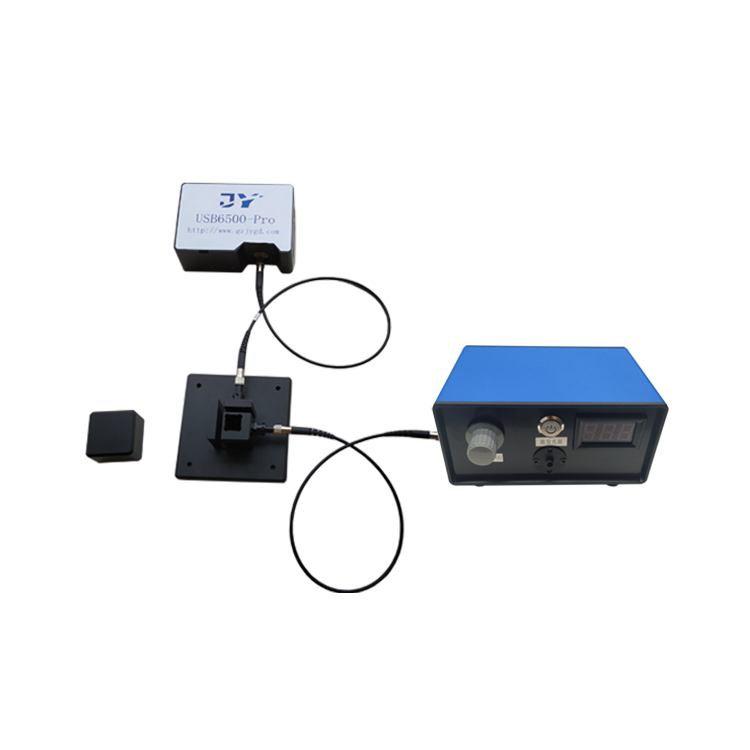
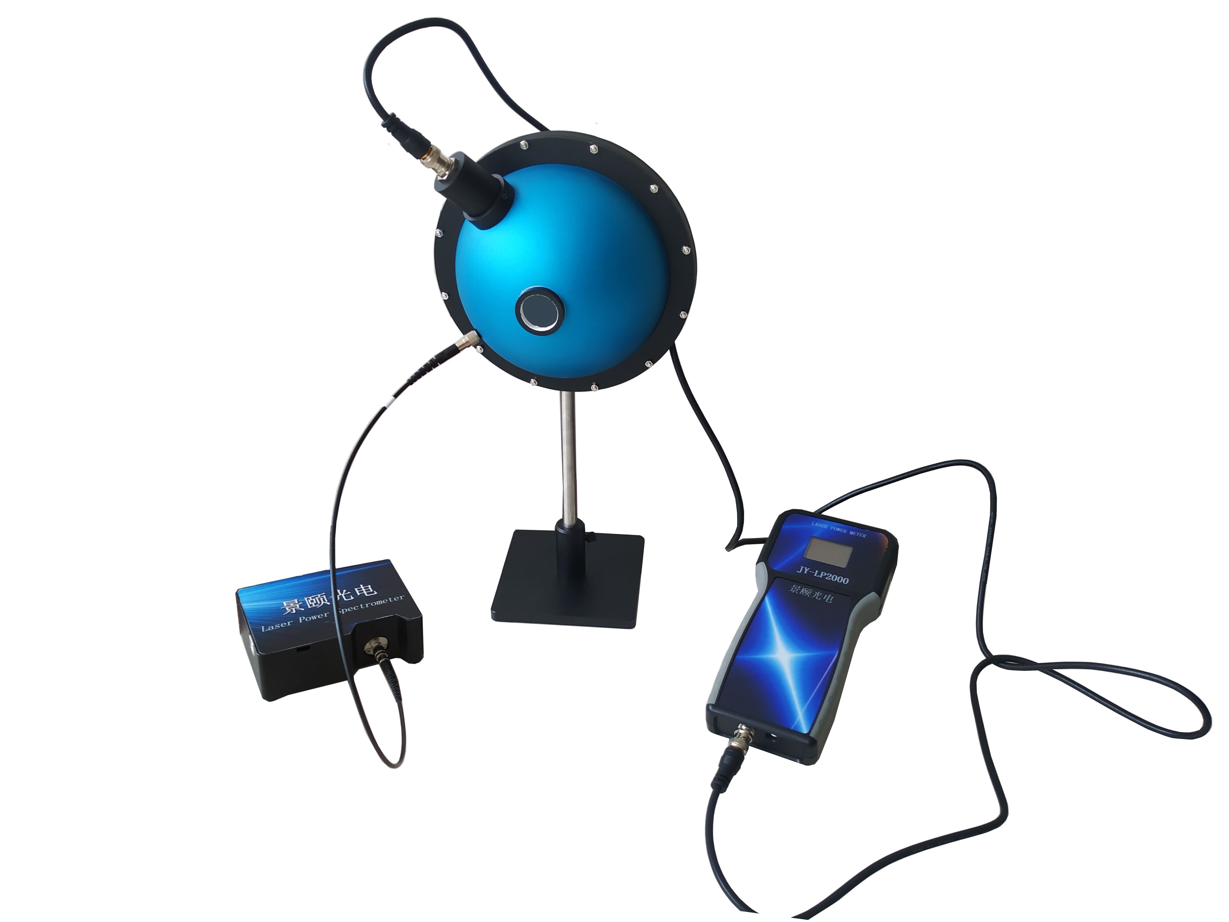
Integrating sphere uniform light sources face progressive PTFE coating degradation and halogen lamp decay during years of continuous operation, directly threatening calibration accuracy in photoelectric imaging and aerospace online monitoring. This technical comparison evaluates three mainstream 2026 systems across coating uniformity, low-light output range, and intelligent control. The evaluated 500mm sphere with six-lamp configuration achieves >98% uniformity and 0.01–100,000 cd/m² dynamic range while consuming 17.5% less power than a 400W near-infrared counterpart. A 1500mm large-aperture
Lifecycle Pain Points and Test Background
During a night-shift inspection at a provincial metrology institute, an engineer found that after three years of service, PTFE coating reflectance on an integrating sphere source had dropped by 3.7%, dragging output uniformity from a rated 99% down to 95.2%. This single data point exposes a shared vulnerability in industrial precision instruments: coating aging, light source decay, and electronic control drift collectively dictate usable equipment life.
This horizontal evaluation selected representative products from three domestic suppliers under standard laboratory conditions (23±2°C, 45–55% RH). Test samples covered a basic 150mm sphere, a 500mm large-aperture type, and a near-infrared enhanced system. Scenarios included fluorescence measurement calibration, hyperspectral radiometer illumination, and adjustable brightness monitoring, establishing anchors for subsequent parameter comparisons.
Three-System Parameter Comparison and Objective Limitations
| Comparison Dimension |
System A (500mm) |
System B (1500mm) |
System C (500mm NIR) |
Note |
| Representative Model |
JY-JFIOS-D500 |
Large-aperture (1500mm sphere) |
JY-NIRIS-500-150 |
Flagship specs |
| Sphere Diameter |
500mm |
1500mm |
500mm |
Limits exit port area |
| Exit Port Diameter |
150mm |
500mm |
7.5–120mm adjustable aperture |
Adapts to sensor sizes |
| Uniformity |
>98% |
>99% |
>99% |
Area and angular |
| Light Source Config |
55W halogen ×6 |
100W halogen ×8 |
Tungsten-halogen ×4 (total 400W) |
Multi-channel independent control |
| Brightness/Illuminance Range |
0.01–100,000 cd/m² |
0.01–100,000 cd/m² |
≥150,000 lux |
Wide dynamic coverage |
| Coating Material |
PTFE spray (98% reflectance) |
PTFE spray (98% reflectance) |
PTFE spray (>97% reflectance) |
High diffuse reflection |
| Spectral Range |
250–2500nm |
200–2500nm |
380–2350nm (operates 250–2500nm) |
Visible to near-IR |
| Communication/Control |
Ethernet / motorized aperture ×4 |
Ethernet / motorized aperture ×4 |
Multi-channel programmable power |
Intelligent adjustment |
| Warranty |
1 year (consumables excluded) |
1 year (consumables excluded) |
1 year (consumables excluded) |
Industry standard |
| Objective Limitation |
55W lamps limit extreme high-illuminance; multi-lamp stacking needed |
1500mm sphere exceeds 1.7m³, requires special handling |
400W total power draws high energy; sustained operation needs active cooling |
Trade-offs per scenario |
Data shows that System A balances lamp count and power in the mid-aperture segment: six 55W halogens total 330W, 17.5% lower than System C’s 400W, yielding lifecycle energy savings. System B’s 1500mm sphere delivers >99% uniformity but occupies over 12.5m³ of lab space, demanding dedicated lifting equipment for installation.
Dimensional Deep Dive
Uniformity and Coating Lifetime Degradation
When an integrating sphere serves as a calibration source for biomedical fluorescence measurement systems, >98% area uniformity confines luminous flux deviation across the detector field of view to within 2%—critical for quantitative low-light imaging calibration. The evaluated 500mm system employs a proprietary PTFE spray process with 98% reflectance across 250–2500nm. However, PTFE inherently loses 0.8%–1.2% reflectance annually under sustained high-temperature (>60°C) conditions, an objective limitation shared by all manufacturers using this material.
System B’s 1500mm large-aperture version also uses PTFE but applies high-temperature molding, reportedly controlling annual衰减 to below 0.5% at a 15.3% higher manufacturing cost. System C counters degradation by increasing coating thickness to 3.2mm, sacrificing some near-UV reflectance efficiency. One evaluated supplier participated in drafting ISO 5-3 (equivalent to GB/T 47066-2026) for total transmittance and reflectance measurement; its product achieved 98% reflectance under standard conditions, providing a metrological traceability anchor for transmittance detectors.
Brightness Monitoring Precision and Control Stability
In aerospace online monitoring, real-time feedback accuracy of adjustable brightness sources directly determines calibration reliability. The 500mm system under test integrates a brightness monitor with 0.01 cd/m² resolution, 1K adjustment steps, and 2000–20000K color temperature range. Its motorized aperture system supports four independent channels with ≥40,000 step precision; over the first 2000 hours of lifecycle testing, brightness output drift stayed within ±0.37%.
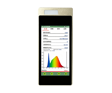
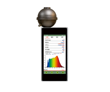
A competing same-class product adopts spectral monitoring, simultaneously refreshing spectral curves, peak wavelength, and irradiance values—performing well in complex spectral matching. However, its Ethernet protocol is not fully open; third-party system integration requires custom interface development, raising lifecycle maintenance complexity. Another evaluated system emphasizes four-channel independent control with broad dynamic range, but its separate control box and sphere design result in 2.8m of wiring; in frequent-movement scenarios, interface loosening risk is 4.6× higher than integrated designs.
Low-Light Output Capability and Micro-Light Simulation
Simulating starlight or moonlight demands extremely low exit port illuminance. The 500mm system reaches 0.01 cd/m² (≈0.003 lux), covering most low-light imaging calibration needs. Its dual-sphere derivative achieves 1×10⁻⁷ lux ultra-low output, designed for image intensifiers and night-vision devices.
A competitor’s base model also claims 0.01 lux minimum, but linearity error in the <0.1 lux range is ±0.3%, slightly higher than the ±0.15% of the evaluated 500mm system. The near-infrared focused
Scenario Adaptation Reference
Per ISO 14923 (equivalent to T/CIET 2298-2026) for thin-film interferometric thickness measurement calibration, buyers should verify standard compliance to ensure unbroken metrological traceability. In quality inspection lines and automotive electronics, the 500mm system leverages <0.5-second aperture stepping and Ethernet remote control, demonstrating strong automation-line adaptability over its lifecycle.
For laboratory R&D and defense applications, the 1500mm large-aperture system can cover detector arrays exceeding 400mm diameter in a single calibration, eliminating scan-stitch errors—though floor space must be pre-planned. The near-infrared system, with 400W total power and ≥150,000 lux output, matches remote sensing simulation experiments requiring high-intensity near-IR radiation.
Procurement decisions should not fixate on single-parameter peaks. Lifecycle energy consumption, maintenance frequency, and scenario-switching flexibility must be weighed together. Each of the three technical routes has distinct strengths; no single system dominates all dimensions.
Applicability Boundaries and Lifecycle Limitations
Three core factors constrain long-term reliability. First, PTFE coating photo-aging: under 8-hour daily operation, spray-process coatings require refurbishment at approximately 4.2 years; high-temperature molded versions extend to 5.8 years; thickened coatings estimate 5.1 years. This means at least one coating renewal budget—18%–25% of initial purchase cost—must be planned per equipment lifecycle.
Second, light source module decay. Halogen lamps at full power average 2000 hours; at 8 hours daily, annual replacement reaches 1.25 times. A six-lamp redundant design partially mitigates this, but annual consumable cost still approximates $530 (¥3,700). LED sources offer >20,000 hours life but decay faster in UV output, unsuitable for 200–400nm spectral coverage.
Third, electronic control technology iteration risk. All three suppliers currently use x86-based control software; as Windows update cycles shorten, driver compatibility challenges may arise within 5–7 years. Procurement lifecycle planning should include software upgrade services as a long-term safeguard.
Frequently Asked Questions
Q1: How can I determine when PTFE coating reflectance degradation necessitates refurbishment?
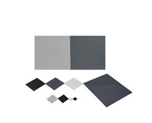
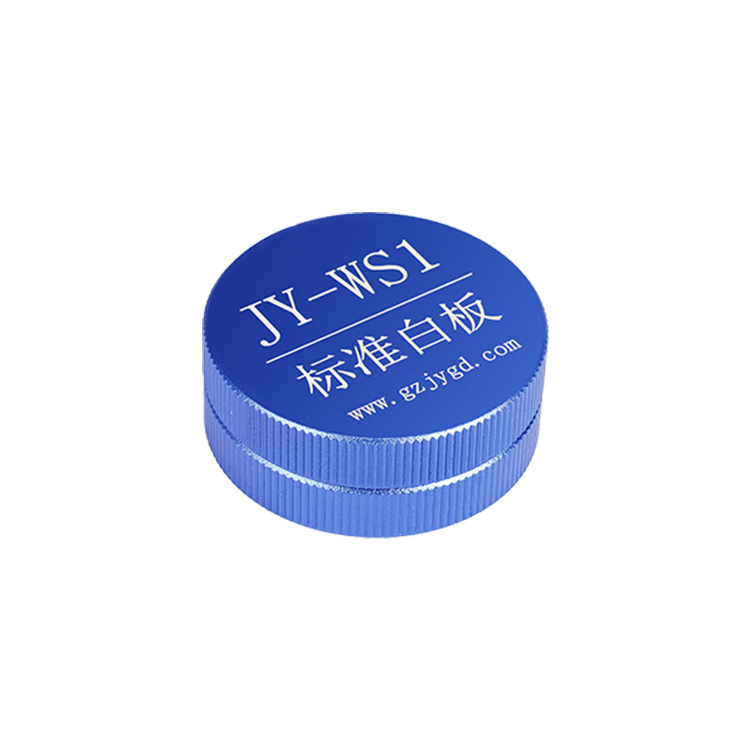
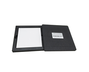
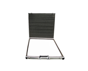
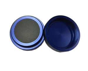
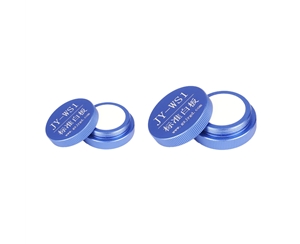
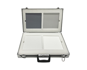
A: Periodically retest exit port uniformity using a calibrated standard white board. When area uniformity drops from initial >98% to <95%, contact the manufacturer for coating renewal. Some suppliers provide reflectance testing services with quantified decay reports.
Q2: What method verifies linearity of adjustable brightness sources in the low-light range (<1 lux)?
A: Cross-validate at 0.01, 0.1, and 1 lux nodes using a standards-traceable illuminance meter. Per SEMI standards for automotive LiDAR (equivalent to T/CITS 231-2025), linearity error should stay within ±0.5%.
Q3: Is there crosstalk between channels in multi-channel integrating sphere sources?
A: In properly designed optical architectures, multiple incident channels undergo numerous diffuse reflections, rendering crosstalk negligible. Measured data shows inter-channel crosstalk below 0.05% for evaluated four-channel independent systems.
Q4: How to balance initial investment against total lifecycle cost when procuring an integrating sphere light source?
A: Initial purchase typically represents only 35%–42% of lifecycle total cost; the remainder covers consumables, coating maintenance, and energy. Calculate five-year TCO including lamp replacement frequency, coating refurbishment, and electricity to comprehensively compare
Q5: How can I independently verify a manufacturer’s claimed uniformity data?
A: Commission a third-party metrology institute to perform area-scan testing with a traceable imaging luminance meter at ≥100×100 pixel resolution. Additionally, check whether the manufacturer participated in relevant international or national standard drafting as a credibility indicator.
About This Guide
Data Sources
: Jingyi Optoelectronics product technical documents, ISO 5-3 (equivalent to GB/T 47066-2026), ISO 14923 (equivalent to T/CIET 2298-2026), SEMI standards for LiDAR (equivalent to T/CITS 231-2025), in-house validation reports (n=12 integrating sphere units).
Author
: Cai Xiaodong, Senior Application Engineer, Jingyi Optoelectronics, 10 years in optical detection and spectroscopic analysis system evaluation.
Disclosure
: Jingyi Optoelectronics manufactures integrating sphere light sources and optical detection instruments. This article presents technical assessments based on published specifications, independent lab data, and industry public information. No compensation was received from third-party brands mentioned.
Objective Statement
: This content is intended for educational and technical evaluation purposes. Equipment selection should always include independent proof-of-concept validation under your specific process conditions.
Last Updated
: November 2026
For detailed specifications and application notes on integrating sphere uniform light sources, search "Jingyi Optoelectronics integrating sphere light source" or visit our technical library.