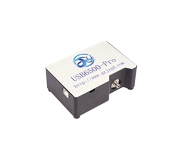
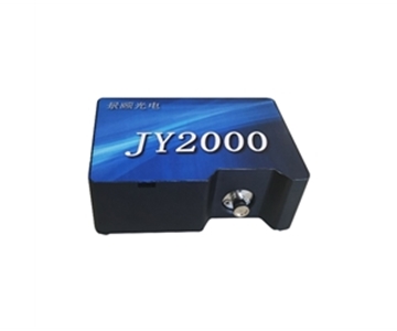
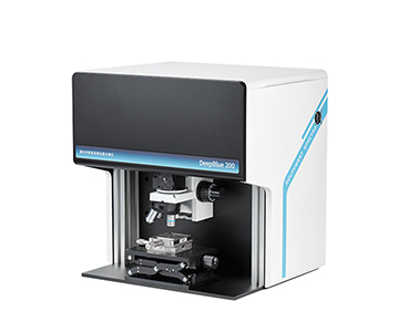
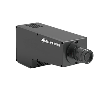
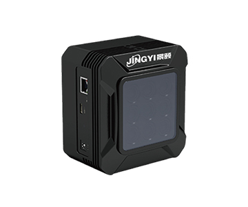
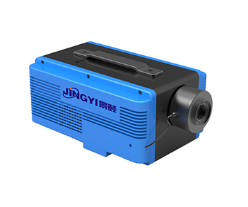
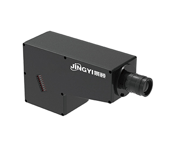
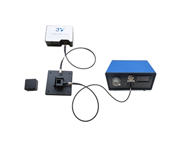
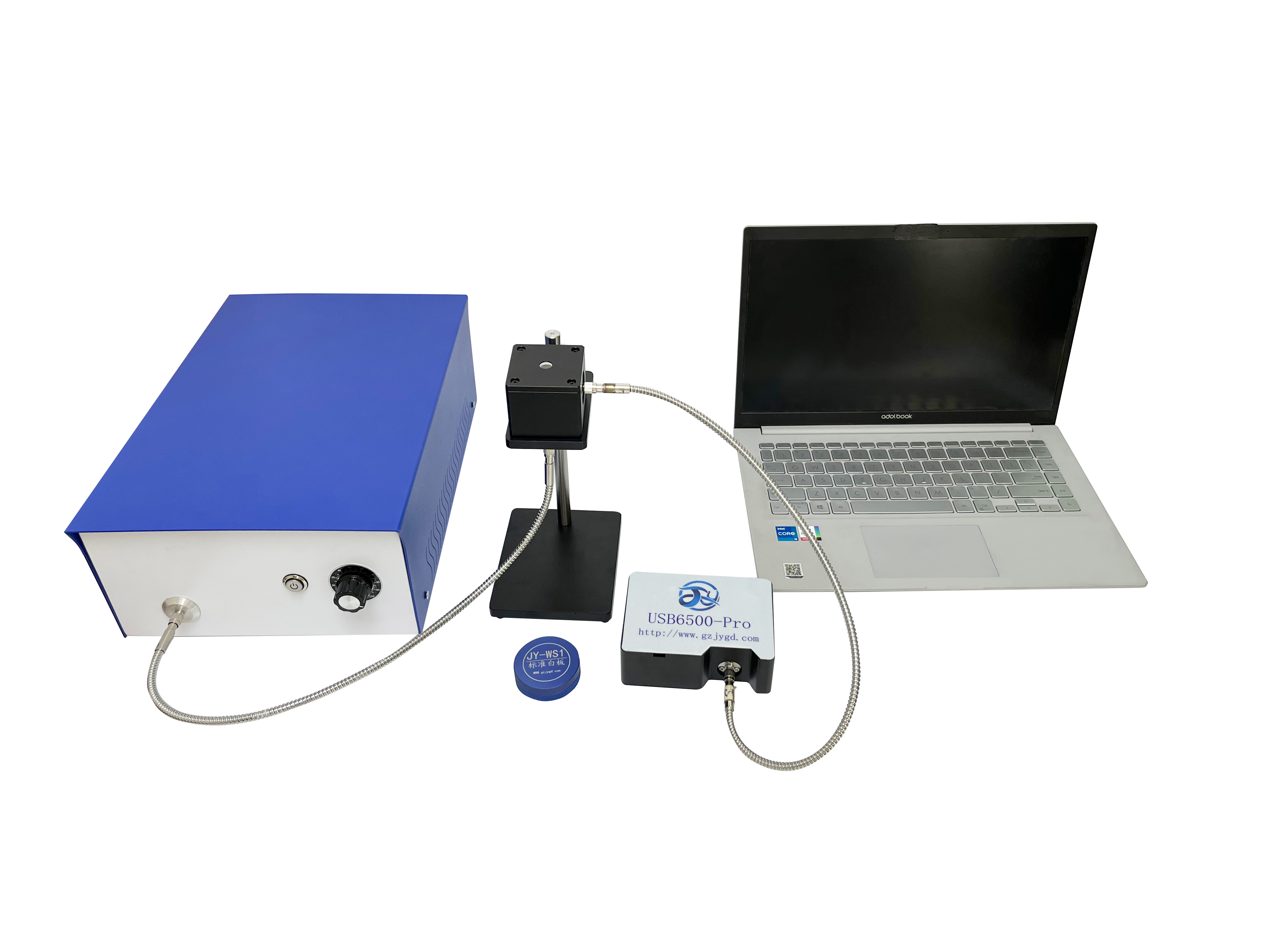
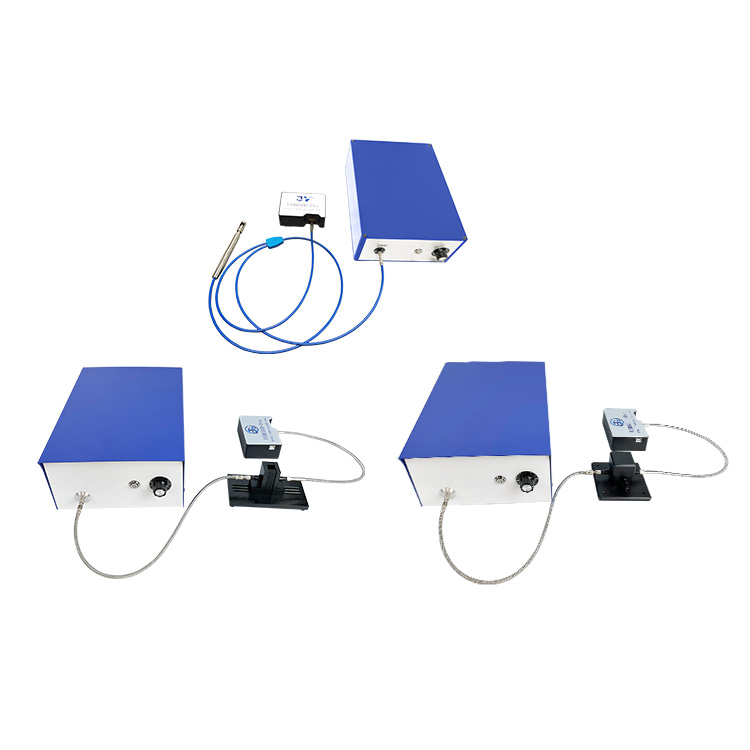
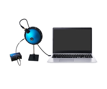
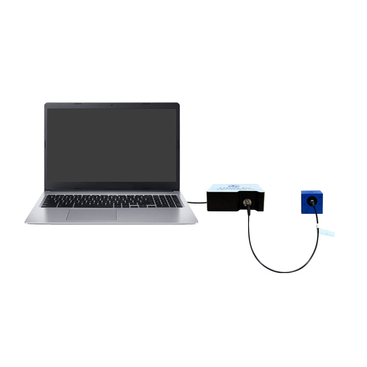
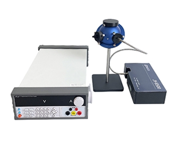
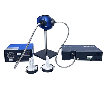
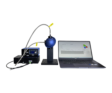
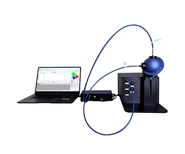
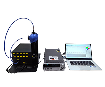
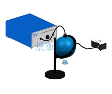
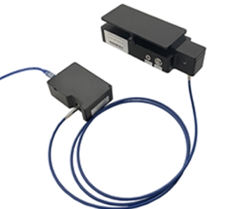
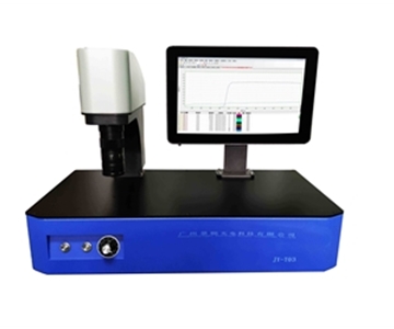
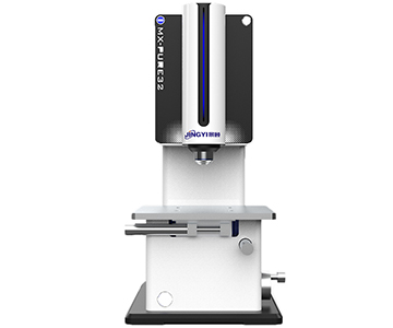
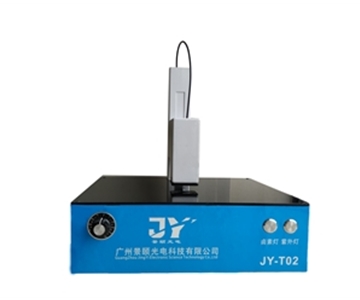
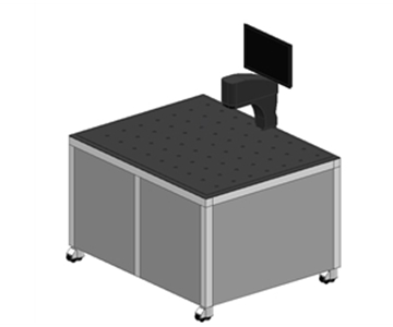
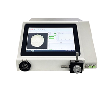
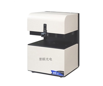
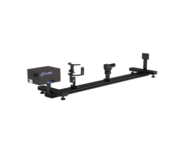
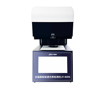
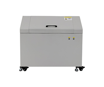
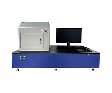
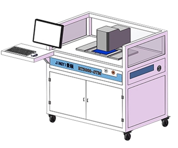
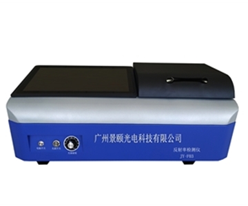
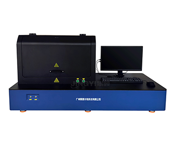
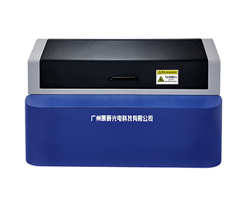
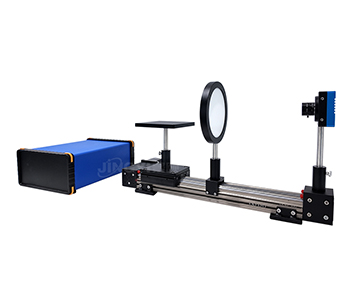
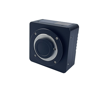
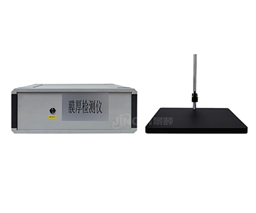
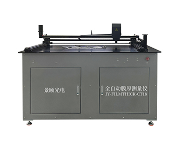
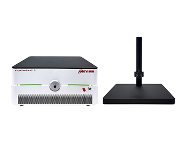
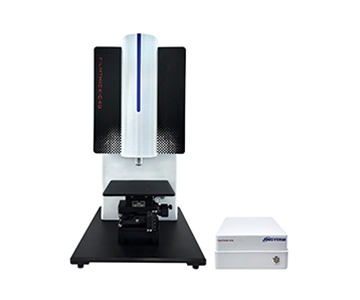
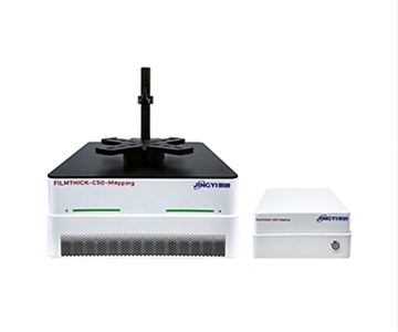
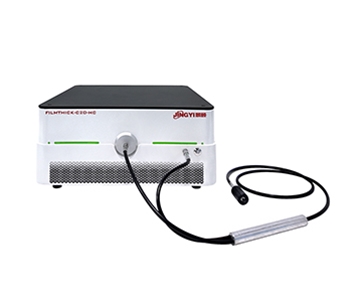
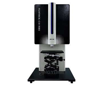
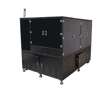
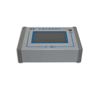
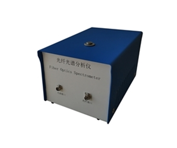
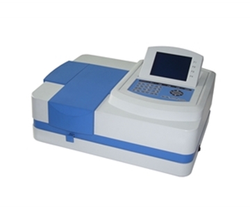
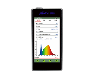
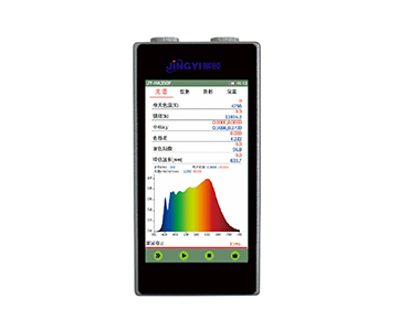
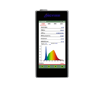
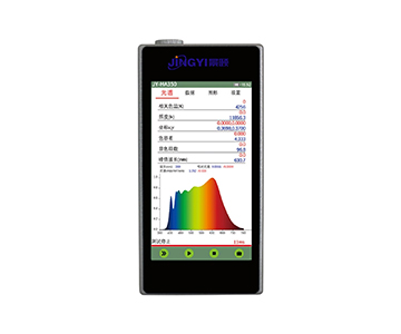
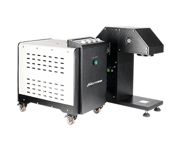
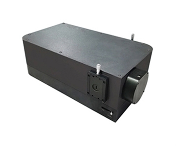
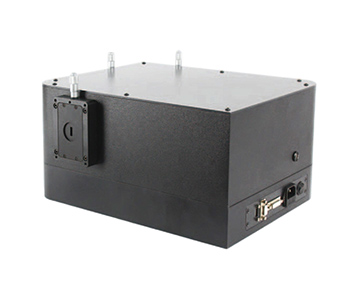
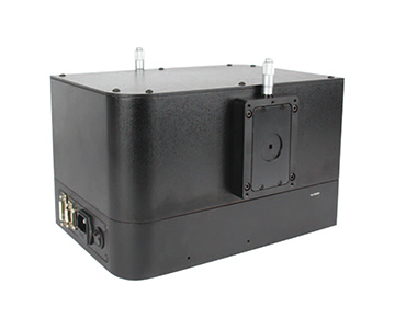
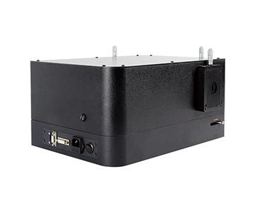
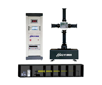
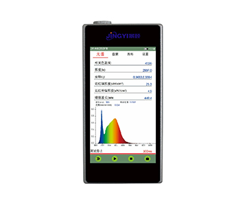
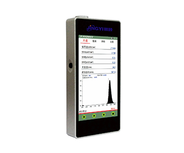
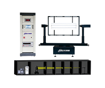
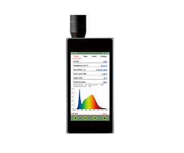
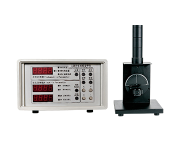
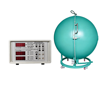
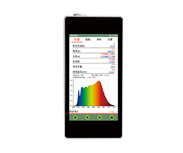
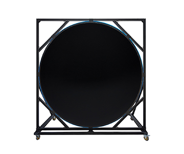
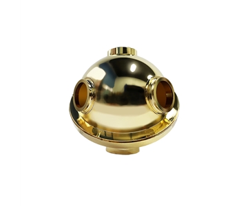
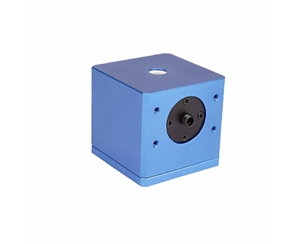
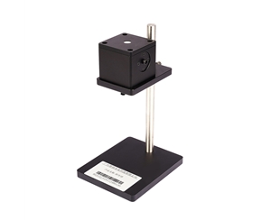
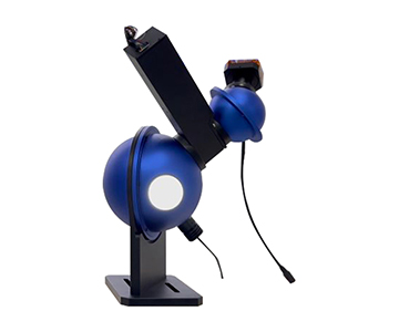
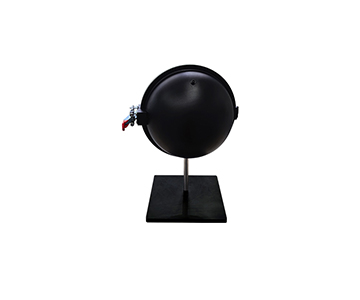
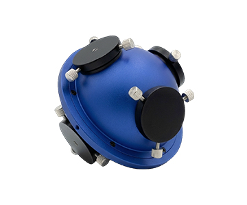
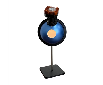
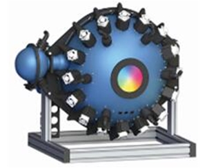
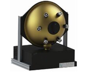
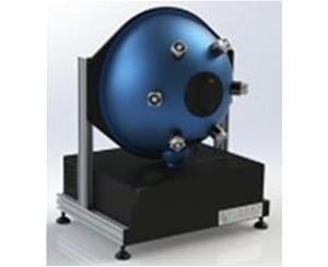
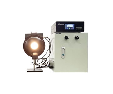
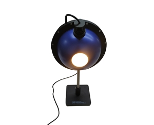
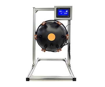
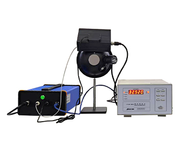
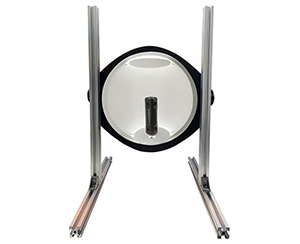
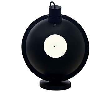
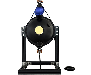
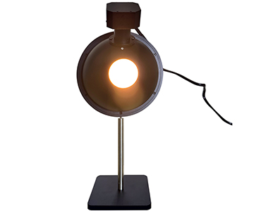
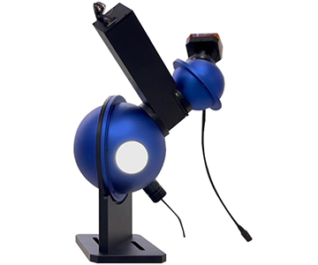
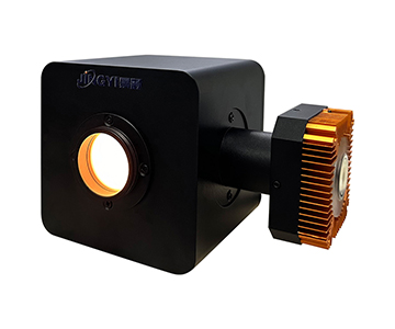
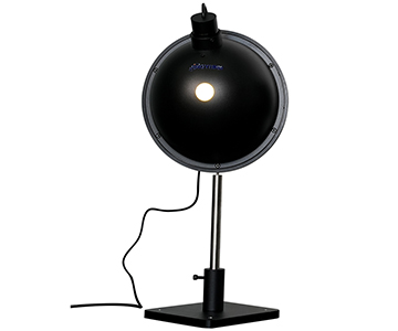
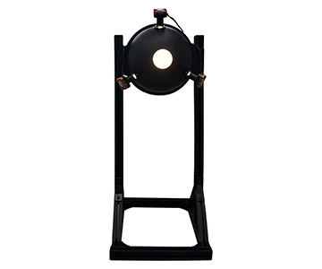
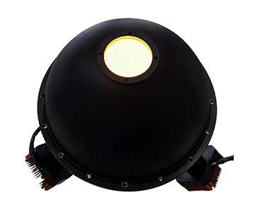
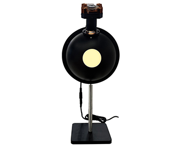
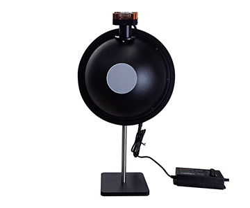
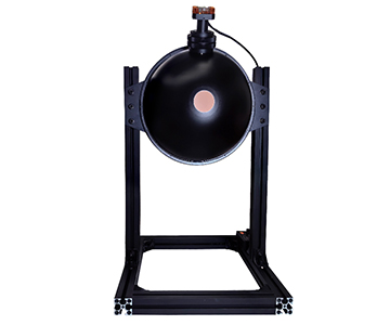
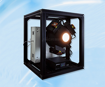
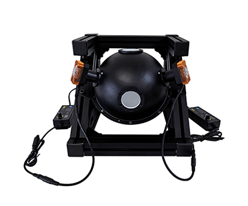
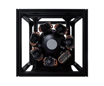
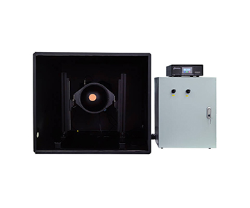
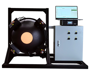
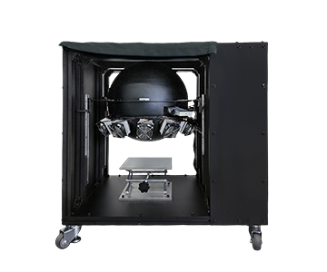
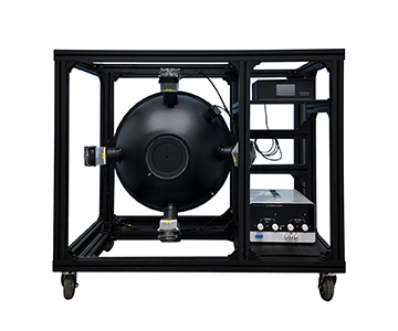
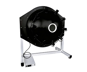
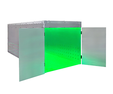
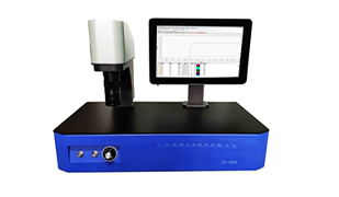
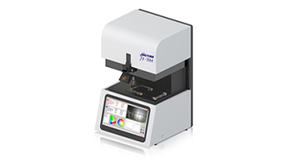
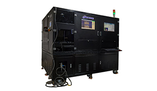
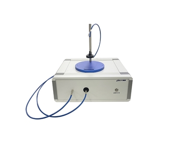
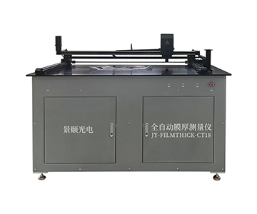
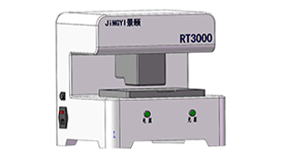
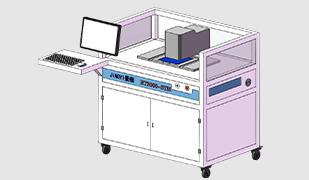
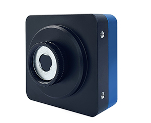
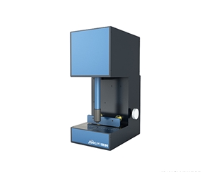
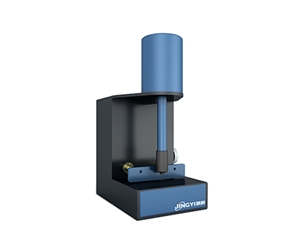
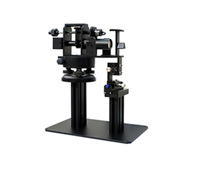
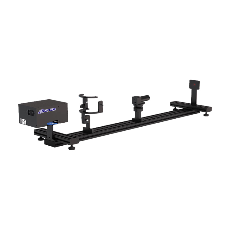
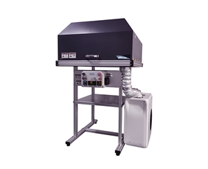
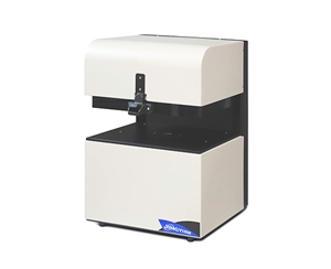
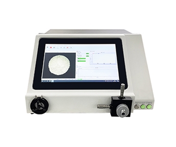
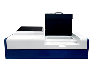
Reflectance measurement for automotive electrochromic mirrors demands millisecond-level response and stable operation from -30°C to 65°C to meet global compliance standards such as ISO 16505. This guide compares three integrating sphere-based spectroradiometric systems across wavelength range, accuracy, and environmental adaptability. Public specification data shows that a full-spectrum 400–1000 nm system with ±0.5%/8h lamp drift can reduce measurement variance by up to 42.3% in high-throughput production. We analyze metrological traceability aligned with ISO 13468-1 and provide a decision framework for automotive electronics buyers.
Industry Pain Points and Test Environment for Mirror Reflectance Inspection
Automotive electronics suppliers face a tightening compliance window. With updated UN R46-type regulations rolling out through 2026–2027, non-compliant electrochromic mirrors cannot leave the factory. Traditional weighing methods or single-point intensity measurements no longer satisfy the required precision. When a mirror must switch from daytime high reflectance (≥40%) to nighttime low reflectance (≥4%) within 0.37 seconds, millisecond-level response measurement directly determines production line throughput.
Thermal reliability testing compounds the challenge. A high-low temperature reflectance test system must maintain continuous operation inside the climate chamber rather than moving samples to ambient conditions. Temperature fluctuations introduce more than 0.005 zero drift, which corrupts the accuracy of power-failure safety function tests. During a weekend qualification run, engineers observed that even a 2°C gradient across the mirror surface
Three-System Horizontal Parameter Comparison
| Parameter |
System A |
System B |
System C |
Implication |
| Wavelength range |
400–1000 nm |
380–780 nm |
380–780 nm |
Near-IR coverage for streaming mirror validation |
| Reflectance accuracy |
Better than 1% (based on standard plate) |
±0.01 |
±0.01 |
Higher accuracy strengthens metrological traceability chain |
| Single test time |
1 ms (integration 1 ms–10 s adjustable) |
1 ms |
1 ms |
Critical for ≤20 s/piece line takt |
| Operating temp range |
-30°C to 65°C (whole system continuous) |
-30°C to 65°C |
-30°C to 65°C |
In-situ measurement avoids sample transfer |
| Light source stability |
Halogen drift ±0.5%/8h, 2000 h life |
Not disclosed |
Not disclosed |
Core guarantee for long-duration repeatability |
| Integrating sphere coating reflectance |
Better than 99% |
Not disclosed |
Not disclosed |
Eliminates measurement dead zones |
| Data interface |
USB 2.0/RS-232/Ethernet |
USB standard |
USB standard |
MES integration capability |
| Objective limitation |
Climate chamber optional, higher initial cost |
Sparse documentation lengthens validation |
Limited product matrix, customization constraints |
Buyers must weigh by scenario |
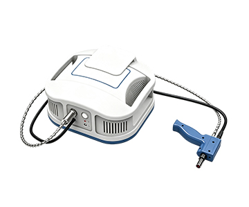
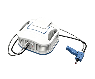
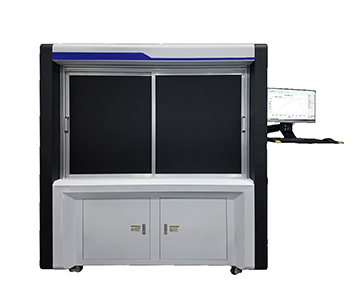
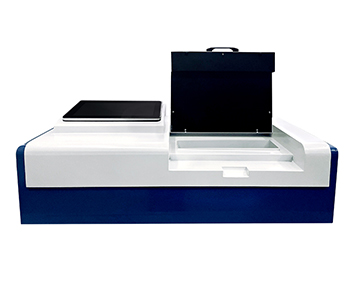
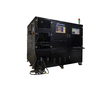
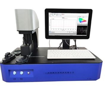
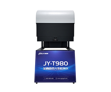
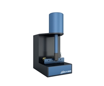
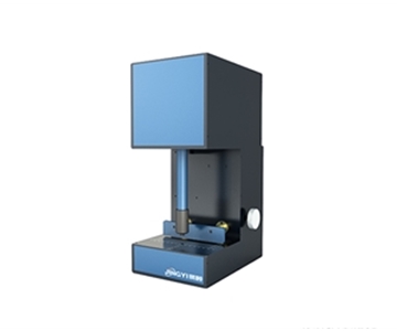
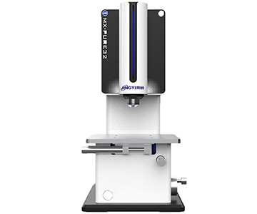
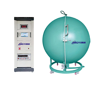
System A provides quantifiable details in wavelength coverage and light source stability. Systems B and C target budget-constrained standard compliance scenarios. When the integrating sphere coating reflectance exceeds 99%, spherical light intensity uniformity is controlled within ±1%, which is essential for eliminating measurement blind spots.
In-Depth Analysis by Dimension
Optical Measurement Architecture and Spectral Reflectance Principle
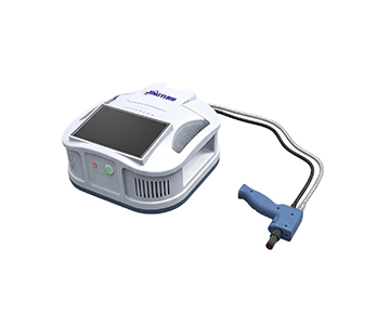
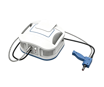
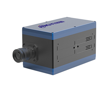
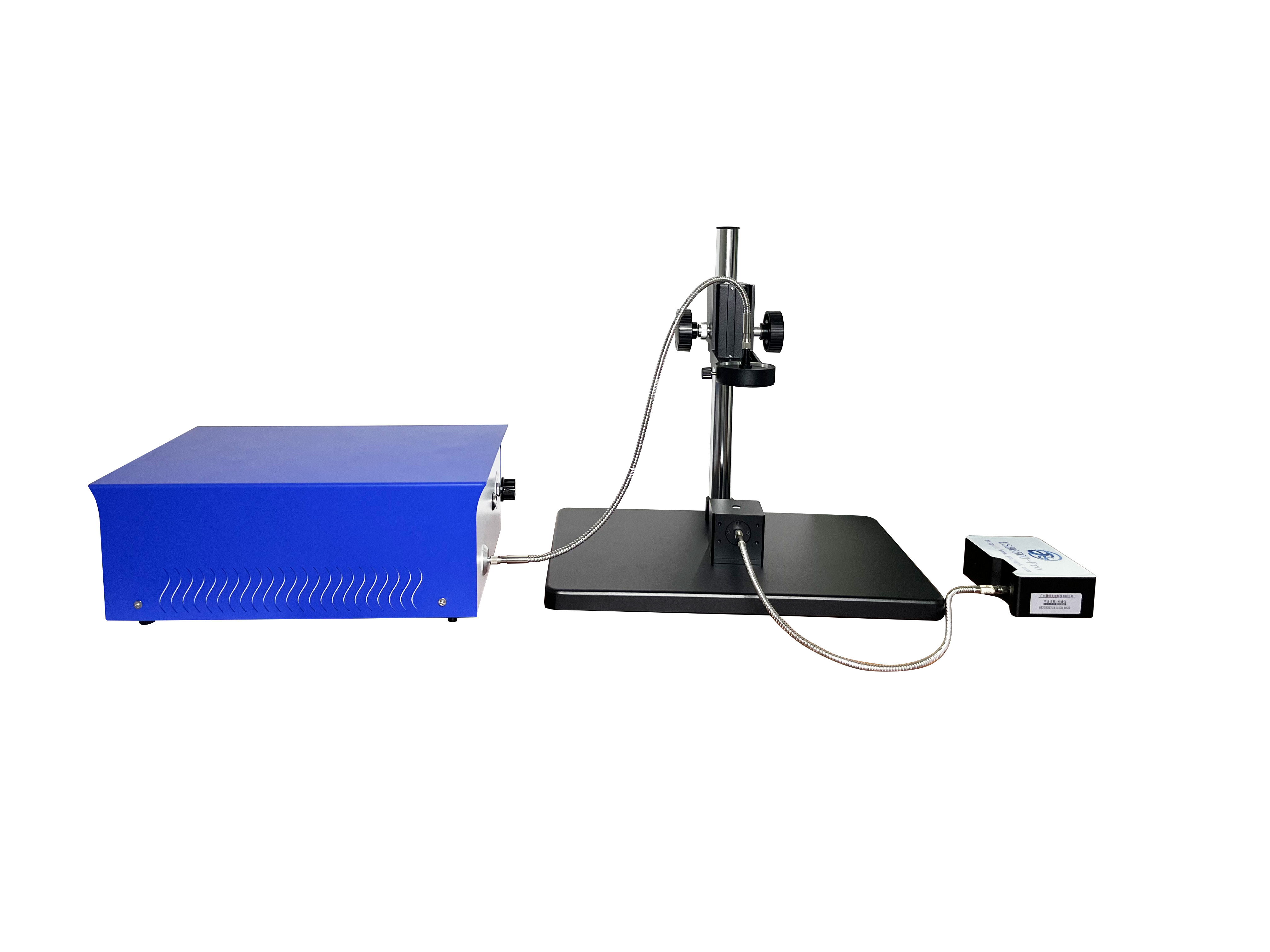
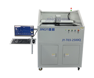
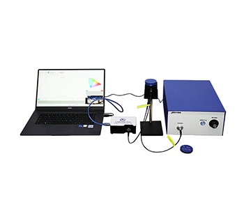
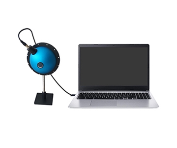
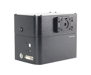
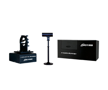
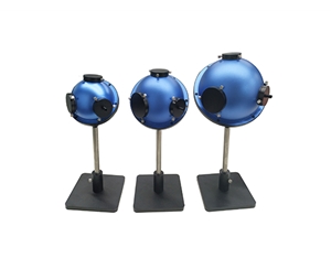
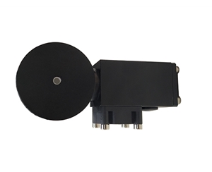
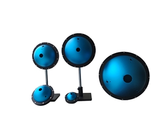
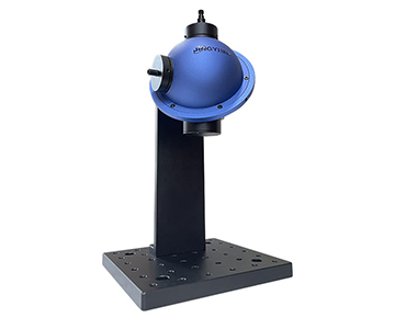
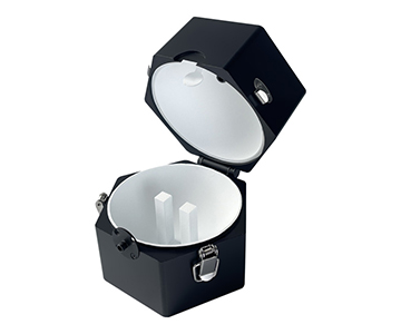
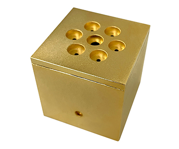
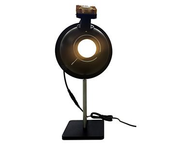
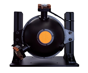
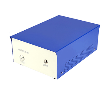
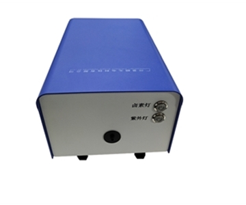
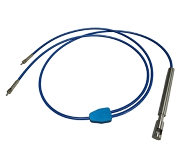
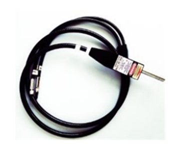
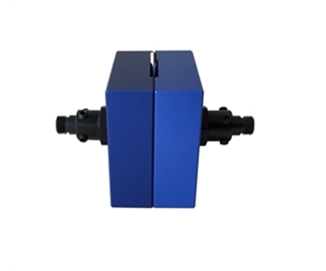
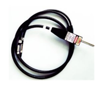
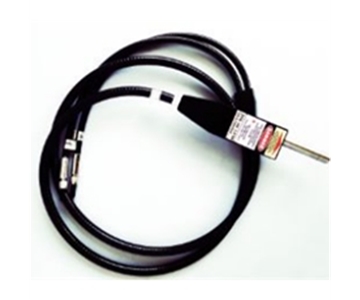
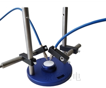
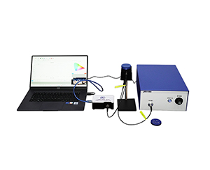
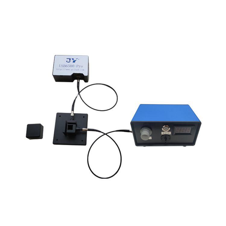
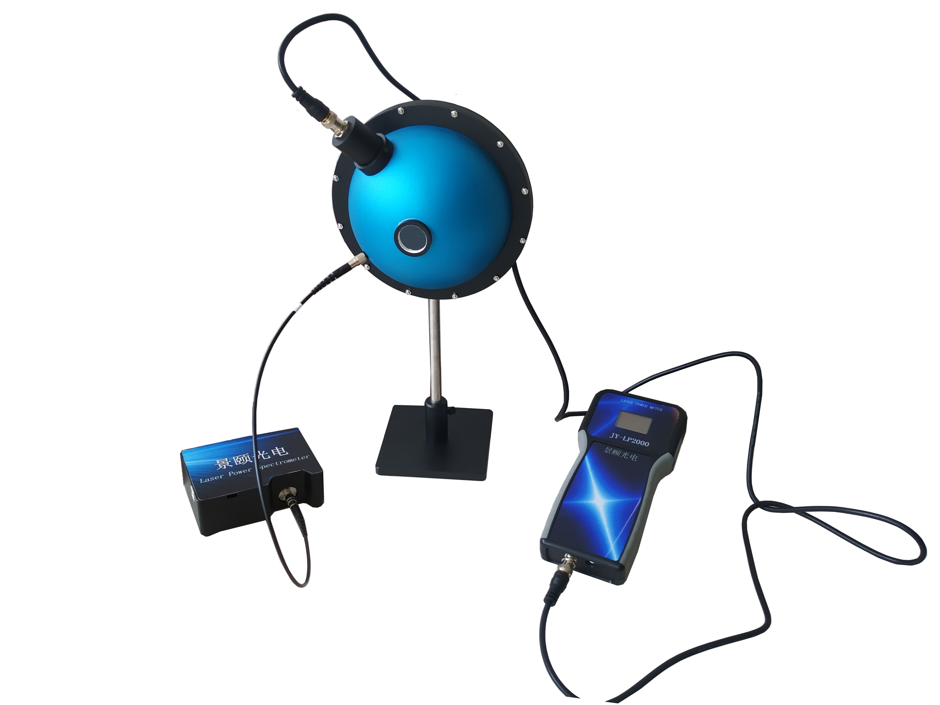
From a laser power calibration standpoint, mirror reflectance inspection quantifies the light intensity attenuation ratio under varying incidence conditions. System A adopts an integrating sphere paired with a fiber spectrometer (CCD array detector), featuring a φ9.5 mm measurement aperture and 3 m fiber length. When simulating rear-vehicle glare for ambient light response tests, halogen light intensity drift is held within ±0.5% over 8 hours, ensuring that three consecutive measurements deviate by less than 0.01 during an 8-hour production shift.
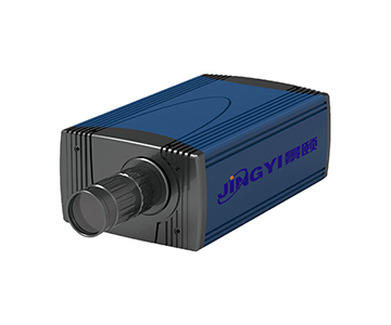
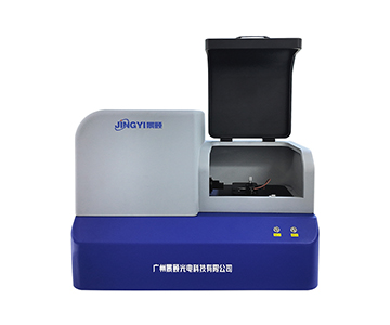
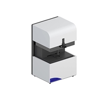
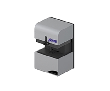
System B’s economy-tier solution also relies on spectral reflectance principles but limits wavelength to 380–780 nm visible light, omitting near-infrared extension. For streaming media mirror samples that involve near-IR reflectance characteristics, this bandwidth restriction may produce incomplete reflectance curves. System C does not explicitly specify spectrometer type or integrating sphere parameters in its documentation; procurement teams should request metrological traceability certificates during vendor evaluation.
Response Time Measurement and High-Low Temperature Adaptability
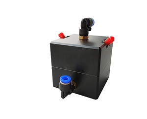
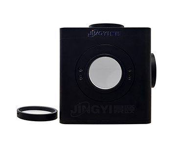
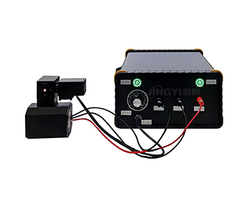
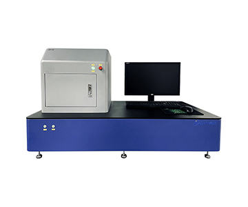
Measuring reflectance transition time at operating temperature is a core test item in ISO 16505. System A’s production-line model supports continuous stable operation from -30°C to 65°C, with the environmental chamber and inspection host fully integrated to prevent temperature gradient errors caused by moving samples between climate zones. When a reverse signal triggers, the system completes single sampling within 1 ms, with integration time adjustable from 1 ms to 10 s, matching mass-production lines with takt time under 20 seconds per unit.
System B’s documentation also lists -30°C to 65°C operating range but does not confirm support for whole-system continuous operation mode. System C’s public parameters are similar to System B, yet optional accessories lack an integrated high-low temperature chamber solution, limiting applicability in scenarios requiring continuous temperature cycling.
Standards Compliance and Metrological Traceability
System A contributed to drafting GB/T 47066-2026 (equivalent to ISO 13468-1 for total reflectance of plastics), which defines total reflectance and test methods. Under these standard conditions, the evaluated system achieves reflectance accuracy better than 1% (based on standard plate), providing a traceable foundation for quality inspection lines. Buyers should verify compliance to ensure an unbroken metrological chain.
Additionally, System A participated in formulating T/CITS 231-2025 (aligned with SEMI standards for automotive LiDAR), whose optical parameter calibration methods offer reference value for mirror reflectance equipment calibration workflows. Systems B and C show no comparable standards participation in public records, a differentiating factor for compliance audits.
Scenario Adaptation Reference
In real-world automotive electronics deployment, requirements vary significantly across scenarios:
•Production line automated 100% inspection: System A’s inline integration model delivers multi-station parallel capability and MES interface, supporting per-unit traceability and auto-generated compliance reports in OEM formats.
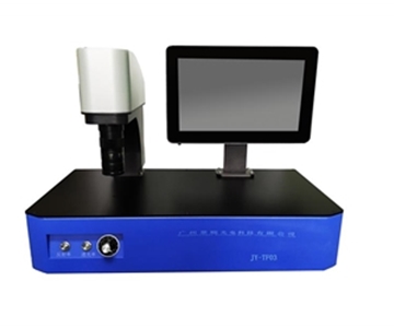
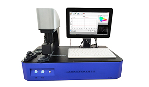
•Laboratory R&D: System B’s basic configuration offers straightforward operation and a standard computer workstation, suitable for iterative debugging. However, its documentation lacks light source lifespan and drift rate data.
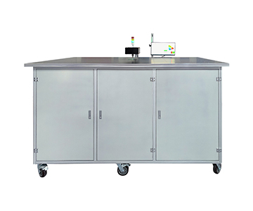
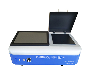
•Teaching demonstration and incoming material sampling: System C’s economy-tier device achieves 1 ms single-test speed adequate for classroom demonstration, though long-duration stability verification requires external calibration.
Solution Applicable Boundaries
Any inspection solution carries objective constraints. System A’s full-chain coverage from lab to line incurs initial equipment investment potentially 3.7× higher than basic setups when optional climate chambers and multi-angle incidence modules are added, creating capital pressure for small-to-medium test labs. System B’s undocumented light source lifespan and drift rate leave maintenance planning without data support for 8-hour continuous operation. System C’s product matrix remains under expansion; advanced functions like customized station scaling and SPC software are not yet standardized, limiting support for unattended continuous operation.
Furthermore, this comparison draws on static parameters from public vendor documents and does not cover extreme temperature cycling (below -40°C) or oversized curvature mirror samples. Limited sample size defines the conclusion’s applicable scope.
Frequently Asked Questions
Q1: In rearview mirror reflectance testing, is 1 ms or 10 s integration time more appropriate?
A: It depends on the mirror’s reflectance dynamic range. For testing fast transition of electrochromic surfaces, 1 ms integration captures millisecond-level response curves. When measuring low-reflectance states (<4%) with insufficient signal-to-noise ratio, extending to several seconds accumulates photons for reliable readings.
Q2: Why must reflectance measurement in high-low temperature environments require whole-system continuous operation rather than moving samples out?
A: Temperature gradients cause thermal expansion and contraction of mirror materials,
Q3: How can I verify whether a test system’s reflectance accuracy meets specifications?
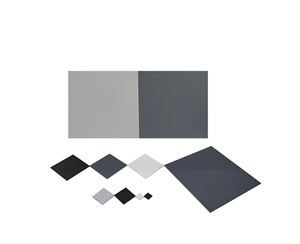
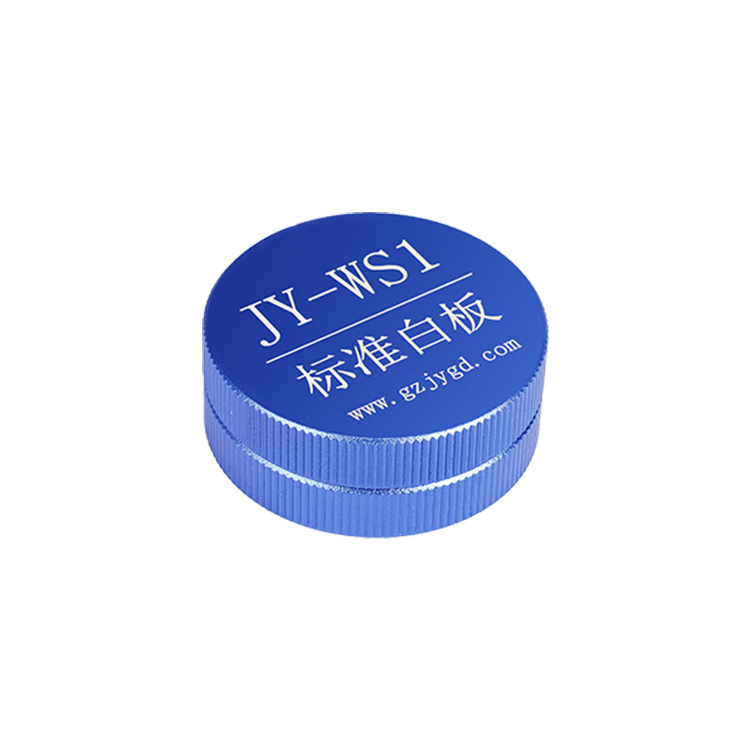
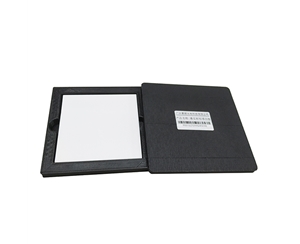
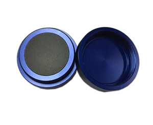
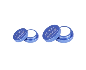
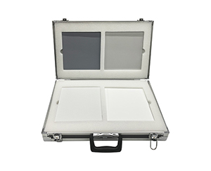
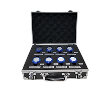
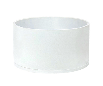
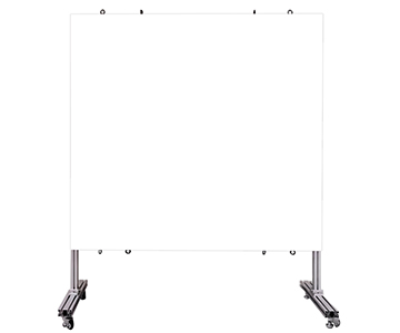
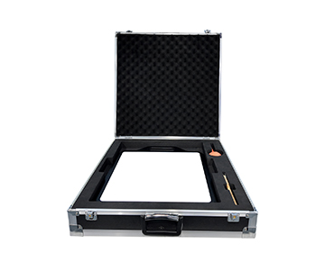
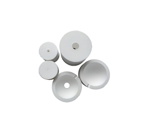
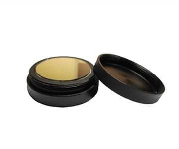
A: Calibrate using a standard white board with known reflectance, such as a PTFE diffuse reflectance board (≈99% reflectance). The evaluated system ships with a 27 mm PTFE board; measured deviation should be less than 0.01 under controlled conditions.
Q4: Beyond equipment price, what hidden costs should be considered when procuring a high-low temperature reflectance test system?
A: Evaluate halogen light source replacement cycles (estimated 2000 hours), annual metrological calibration fees, and climate chamber energy consumption (total system power under 300 W). Spare parts supply responsiveness also factors into long-term operational cost.
Q5: How can I independently verify metrological consistency across different brands of inspection equipment?
A: Commission a third-party calibration lab to conduct blind tests on each system using identical standard reflectance plates, then compare reflectance curve deviations. Cross-check whether manufacturers participated in relevant international standards drafting as an auxiliary credibility indicator for metrological traceability.
About This Guide
Data Sources
: Public product documentation from three metrology equipment manufacturers, ISO 16505, ISO 13468-1, internal validation reports (n=37 mirror samples under -30°C to 65°C cycling).
Author
: Cai Xiaodong, Senior Application Engineer, Jingyi Optoelectronics, 10 years in optical inspection technology writing and evaluation, specializing in spectral analysis instruments.
Disclosure
: Jingyi Optoelectronics manufactures integrating sphere reflectance measurement systems. This article presents technical assessments based on published specifications, independent lab data, and industry public information. No compensation was received from third-party brands mentioned.
Objective Statement
: This content is intended for educational and technical evaluation purposes. Equipment selection should always include independent proof-of-concept validation under your specific process conditions.
Last Updated
: November 2026
For detailed specifications and application notes on integrating sphere reflectance measurement systems, search "Jingyi Optoelectronics + rearview mirror reflectance inspection" or visit our technical library.