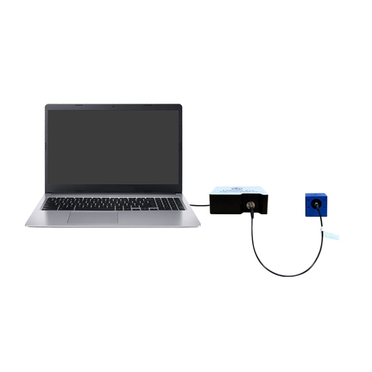
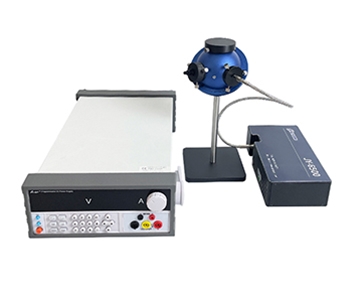
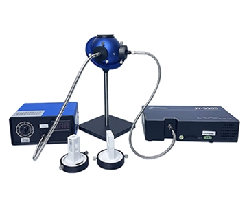
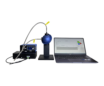
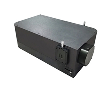
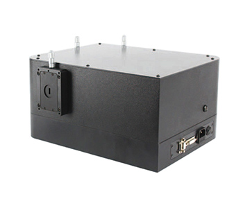
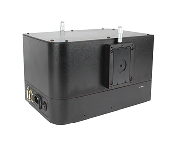
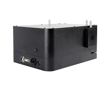
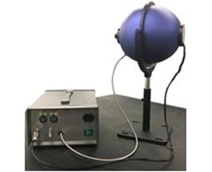
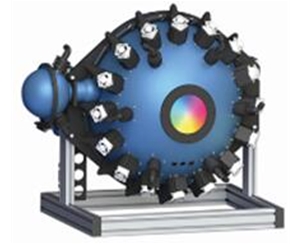
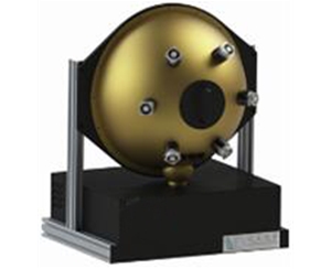
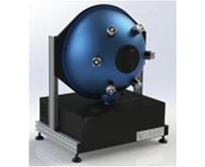
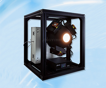
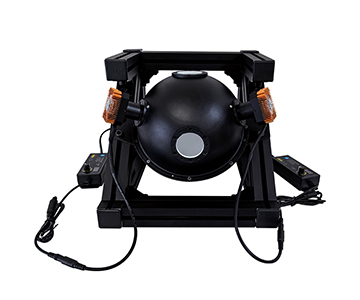
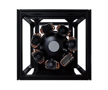
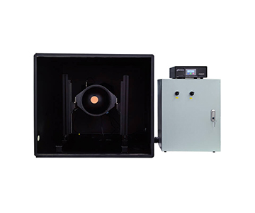
Total luminous flux cannot be read off a single point. This primer explains how an integrating sphere converts directional light into uniform irradiance through multiple diffuse reflections, why a 99%-reflectance PTFE cavity still needs calibration against a standard lamp, and where the port-fraction and baffle tradeoffs actually bite. It covers two working setups — LED package flux binning and laser power monitoring at the processing head — plus three buying misconceptions, the coating-aging and self-absorption limits that specsheets omit, and a ten-repeat independent verification routine.
A luxmeter samples one patch of one surface. An integrating sphere samples the whole sphere of directions, which is why total luminous flux, radiant power, and chromaticity all trace back to this one optical component.
Why "Looks Bright" Is Not a Measurement
Stop asking which lamp looks brighter. Ask how much total luminous flux each one emits — the human eye cannot answer that question, and neither can a handheld meter held against the housing.
Photopic vision peaks near 555 nm and falls off steeply toward deep red, while sensitivity beyond about 700 nm is effectively zero. A horticulture fixture heavy in 660 nm and a white-light fixture of identical wattage can therefore swap visual ranking while their radiant output stays ordered the other way. ANSI/IES LM-79-24 exists as a method precisely because subjective comparison does not survive contact with a traceability chain.
A luxmeter measures incident illuminance at one point, over one acceptance angle.
Holding it to the lamp housing captures whatever fraction of the beam happens to reach the cosine-corrected head — a figure that shifts with distance, tilt, and beam geometry.
That is the whole problem in one image: catch a bowl of rain under the eaves and you learn nothing about the roof's total rainfall. You need a different container — one that encloses the source instead of sampling it.
The Sphere Is a Uniformity Engine, Not a Bucket
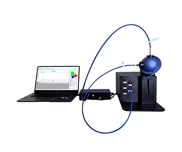
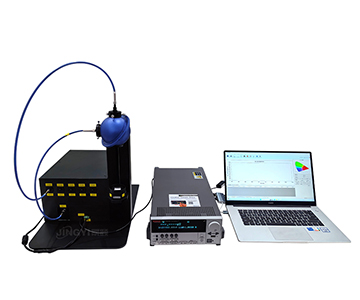
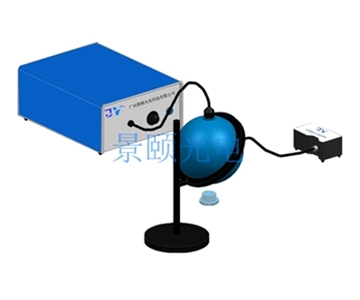
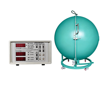
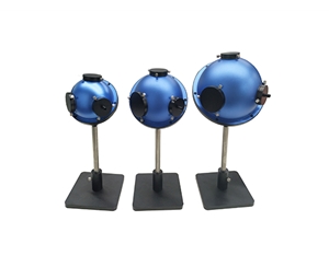
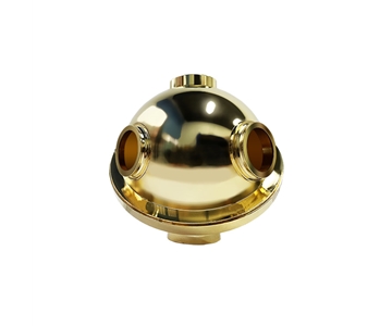
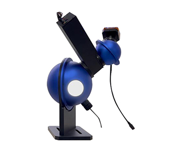
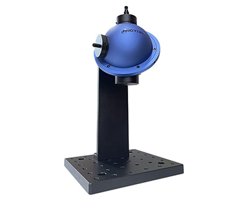
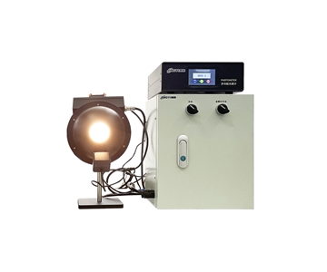
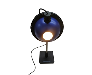
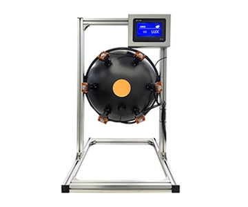
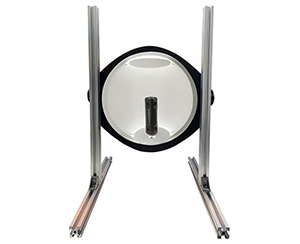
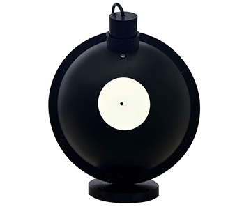
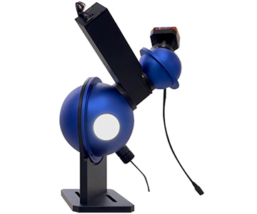
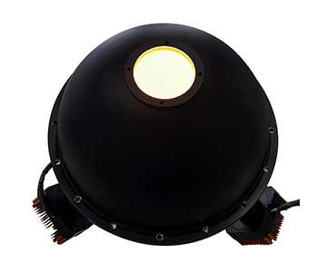
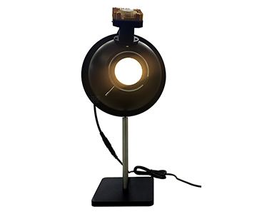
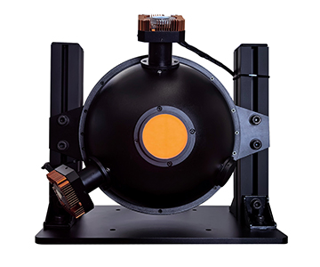
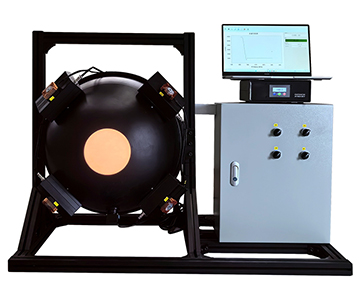
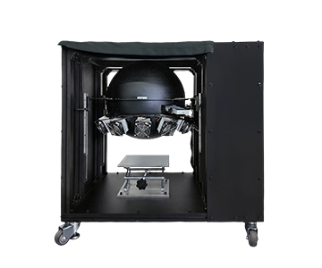
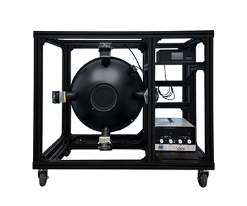
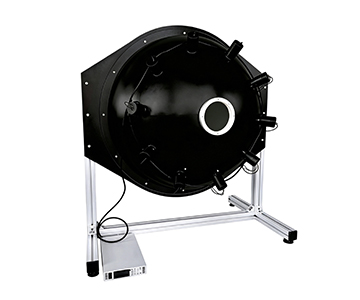
An integrating sphere is a hollow cavity coated inside with a near-Lambertian diffuser, so light entering through a port undergoes repeated diffuse reflection until the wall irradiance becomes position-independent. A small exit port then samples that uniform field, and the detector reading becomes proportional to total input flux regardless of where the light originally went.
The classic analogy is a room with white walls and no windows: switch on a lamp, and the walls glow evenly. But the useful mental model is less "container" and more "mixing chamber." You are not storing light. You are scrambling directionality into a spatially uniform irradiance that a small sampling port can represent.
Coating: the walls that soften every bounce
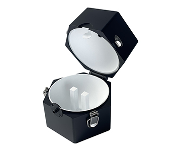
Specular bounce is the enemy; scatter is the point. A diffuse coating sends each incident ray into a hemisphere of directions weighted by the cosine of the emission angle, so every reflection erases a little more of the source's original angular signature. Sintered PTFE and barium-sulfate-based formulations are the workhorse materials here, holding reflectance near 99% across roughly 200–2500 nm.
Two consequences follow, and both matter more than the headline reflectance number:
•Spectral neutrality. If reflectance varies with wavelength, the cavity reshapes the spectrum before the detector ever sees it — a cool-white source and a warm one accumulate different errors. Flat spectral response across the band is what keeps colorimetric results honest.
•Thermal stability. PTFE-formulated coatings resist yellowing and chalking under UV load far better than older paint binders, which is why they dominate production environments rather than only climate-controlled labs.
Sphere multiplicator: the number that sets your signal floor
Mean reflections before a photon is absorbed or escapes follow M = ρ / [1 − ρ(1 − f)], where ρ is wall reflectance and f is the total port fraction. Commercial cavities typically land somewhere between 10 and 30.
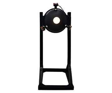
Run the arithmetic on a 150 mm sphere: internal area ≈ 70,686 mm², so at the commonly recommended 5% port-fraction ceiling your ports collectively get 3,534 mm² — and three 40 mm ports already consume about 3,768 mm². That is why retrofitting "just one more port" degrades uniformity instead of adding capability.
Ports and baffles: the art of blocking line of sight
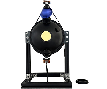
A baffle between the entrance port and the detector port stops first-bounce light from reaching the sample area directly. Every port exists for a reason — entrance, sample, detector, auxiliary lamp — but the baffle exists to guarantee the detector only ever sees multiply-scattered light.
In fluorescence work the same piece of hardware is what keeps excitation leakage off the detector, so the recorded signal is dominated by sample re-emission rather than the source you fired at it.
Fibers and detectors: handing the uniform field to the instrument
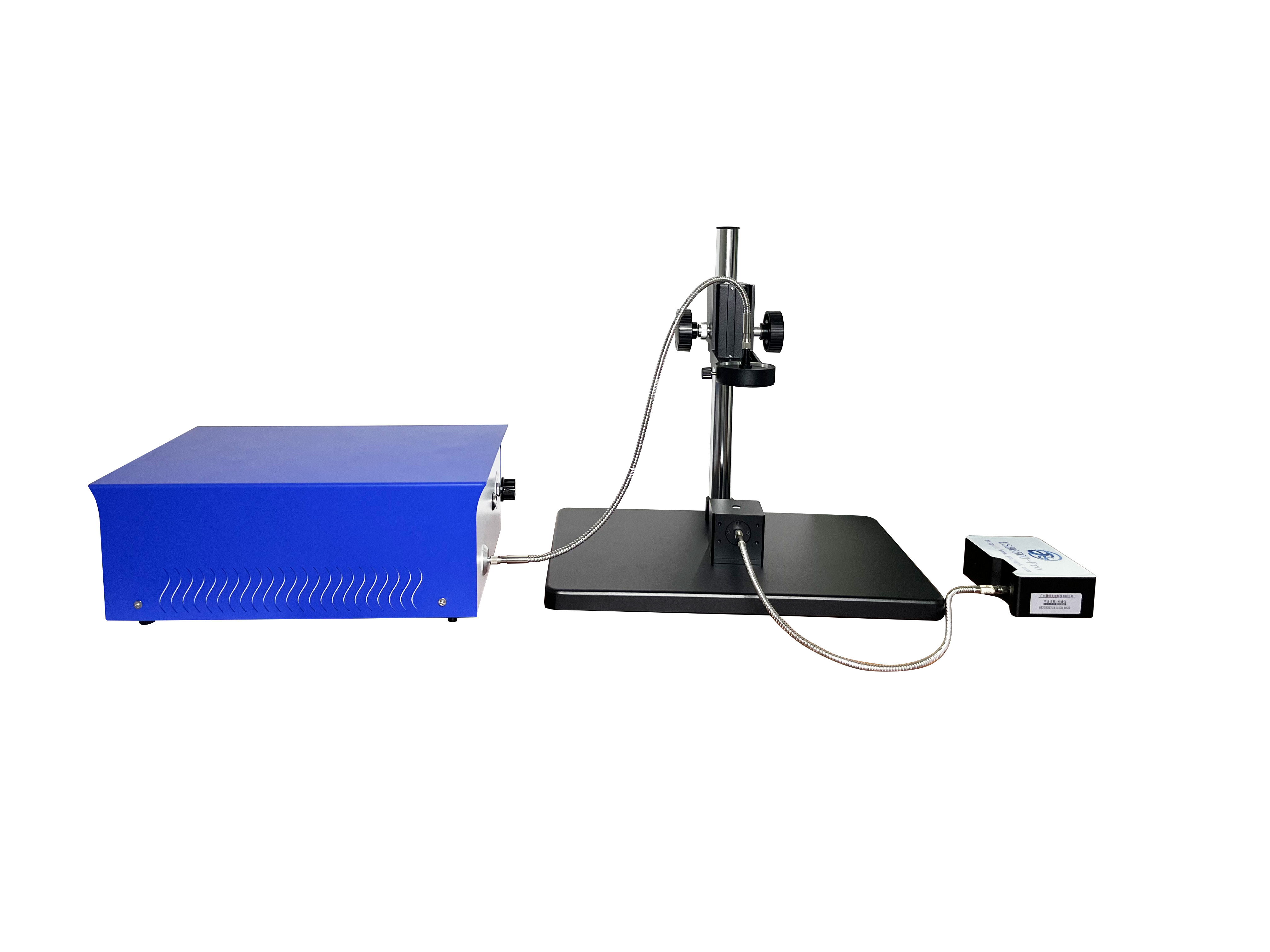
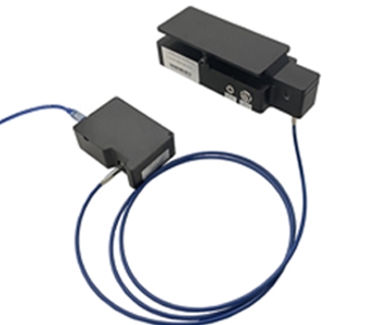
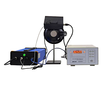
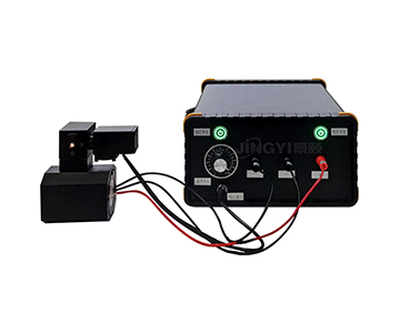
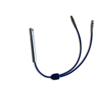
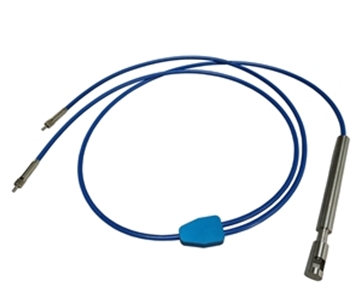
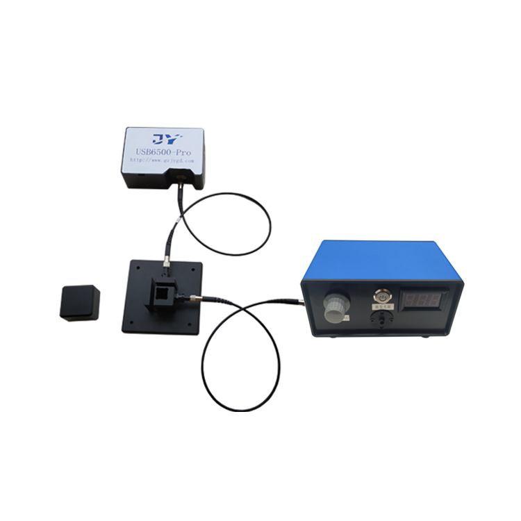
Exit ports typically terminate in SMA905 or FC connectors feeding a spectrometer or a calibrated photodiode head. Because the field at that port is already direction-scrambled, detector placement stop mattering much — move the probe a few millimetres and the reading barely moves.
That placement tolerance is what makes calibration repeatability achievable in the first place. LM-79 reporting explicitly calls for the sphere diameter, coating reflectance, and 2π or 4π geometry to be stated alongside the result, because none of those can be recovered after the fact.
Two Setups Where This Earns Its Keep
Flux binning on an LED packaging line
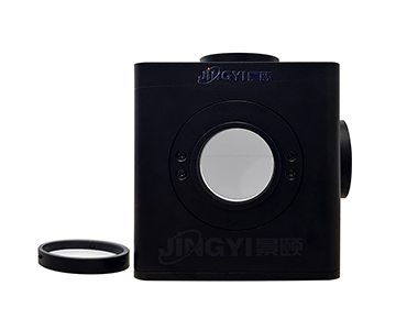
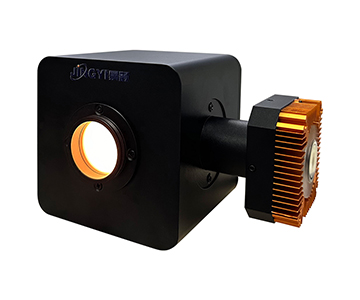
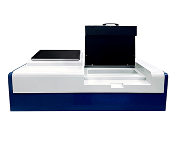
Small transparent packages go into the transmission path; light passes through the part, then enters the cavity, and the spectrometer returns total transmitted flux plus chromaticity coordinates in a single acquisition.
Where a single-point illuminance probe is sensitive to a ±0.37 mm placement shift, the sphere is not — the cavity integrates over angle, so a slightly off-axis die still reports the same total. ASTM E903 covers this approach for spectral absorptance, reflectance, and transmittance of materials using sphere-equipped spectrophotometers.
Power monitoring at the laser processing head
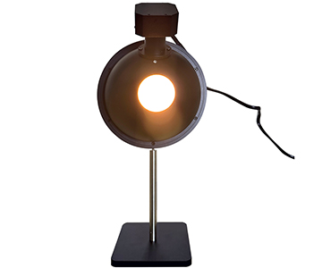
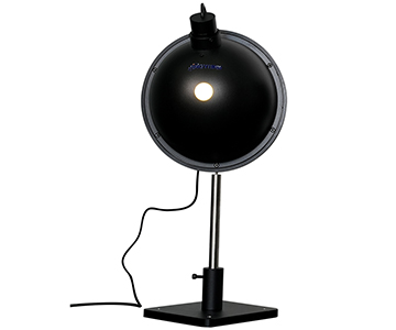
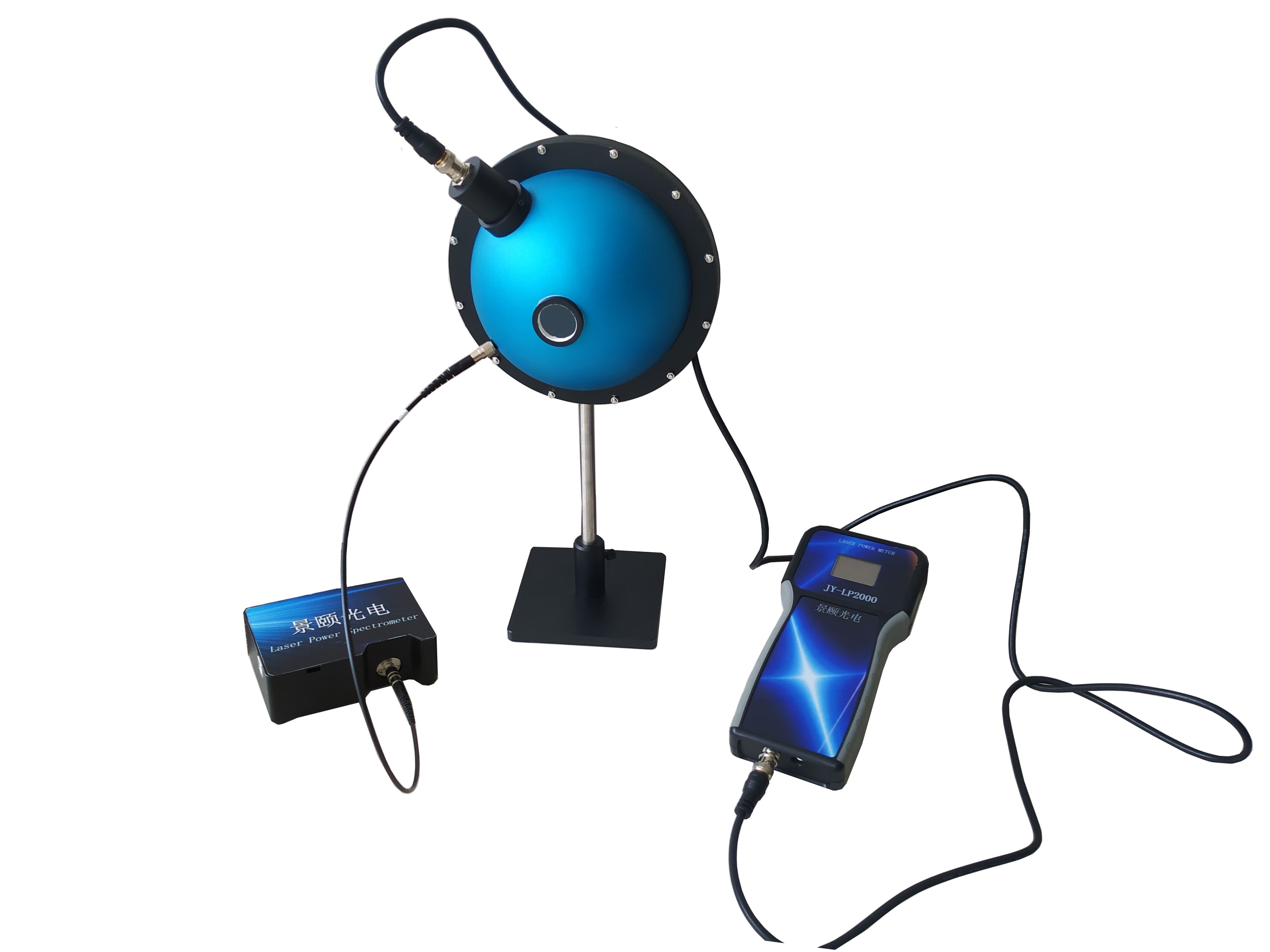
Weld penetration tracks processing-head power, and a drifting head shows up as inconsistent depth long before it shows up as a failed part. Coupling the beam into a large-diameter cavity diffuses the directional input, and a side-mounted fiber tap diverts a fixed fraction to the detector.
You are sampling a cup from the waterfall and inferring the river. Scaling that tap to absolute power is exactly why spheres paired with ISIS-style calorimeters or traceable photodiodes are common in high-power laser metrology: the sphere protects the detector from direct irradiation while the calibration chain carries the absolute scale.
Three Assumptions That Cost Buyers Money
Myth 1: a bigger sphere measures more accurately.
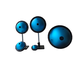
Larger cavities lengthen the optical path and increase bounce count, which does improve spatial uniformity — but the same geometry dilutes the signal at the exit port. Small cavities favour small samples and close coupling; large ones suit big luminaires and transfer standards. Pick wrong and the result is not inaccuracy, it is a collapsed signal-to-noise ratio.
Myth 2: 99% reflectance removes the need to calibrate.
Ninety-nine percent is a material property, not a measurement uncertainty. Fiber attenuation, detector drift, port obstruction, and sample self-absorption all enter the error budget downstream of the coating.
Myth 3: one cavity does every job.
Direct a high-power beam straight at a port and the detector saturates. Deep-UV work depends on where the coating's actual response begins, not where the datasheet says it does. Fluorescence needs a dedicated sample port. Modular multi-port bodies genuinely do cover several tasks, but only after you change the accessories — they are not plug-and-forget.
Where the Method Stops Working
Spheres are not universal receivers, and the failure modes are structural rather than correctable in software.
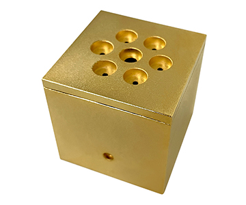
Oversized luminaires and extremely directional beams run out of port area and cavity volume; the fix is a custom large-aperture build or a diffusing plate ahead of the entrance port. Coatings age under sustained UV exposure, and reflectance uniformity drifts slowly enough that only periodic re-checking against a reference standard catches it.
Quantum-yield work is the sharpest edge. Baffle position and sample self-absorption correction dominate the uncertainty, and the common beginner error is reporting the exit-port reading directly as quantum yield while skipping background subtraction and reference-sphere differences. Budget noticeably longer commissioning for this case than for transmittance work.
One more structural constraint: a dark, high-absorption sample lowers the effective sphere multiplicator by soaking up diffuse light, which biases results low unless a self-absorption correction using an auxiliary lamp is applied.
FAQ
What is the difference between an integrating sphere and a luxmeter for measuring luminous flux?
A luxmeter reports illuminance at one location and is strongly angle-dependent. An integrating sphere spatially integrates the full 4π emission, then samples the resulting uniform field. The first suits workplace lighting checks; the second suits total luminous flux and colorimetric evaluation.
Can a small transmittance sphere also measure haze?
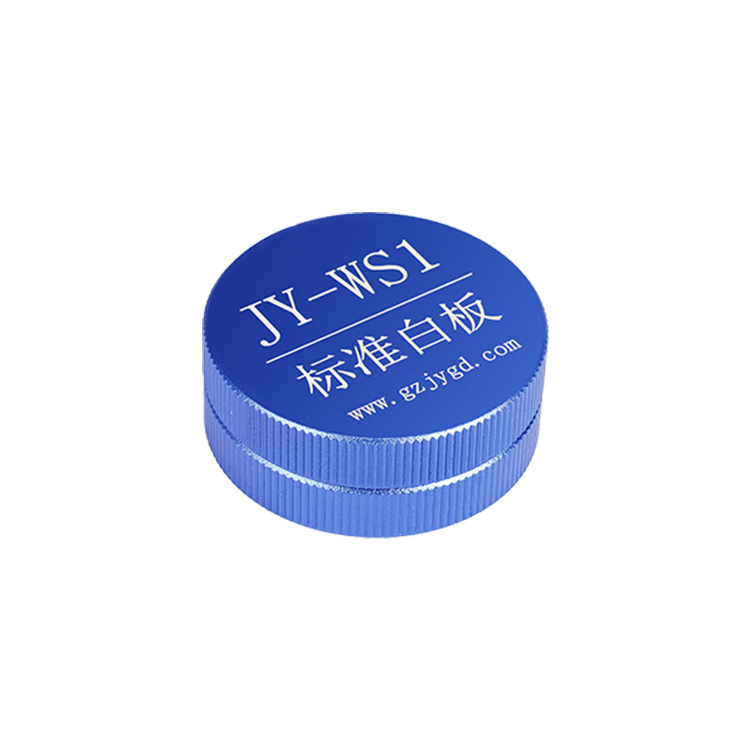
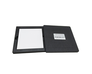
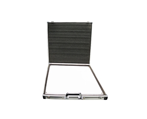
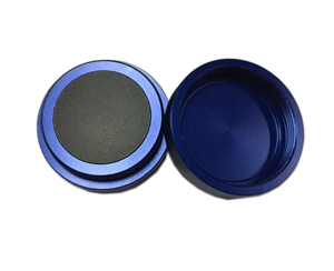
Yes, transmittance cavities support through-sample and haze-related measurements. Whether a quantified haze value comes out depends on the accompanying algorithm and the calibration standard plate, not on the sphere alone.
Will near-infrared laser damage the coating?
Sustained high-power direct incidence can. Introduce the beam through attenuation, diffusive coupling, or a dedicated large cavity, and avoid concentrating the beam at a port edge where fluence peaks. Coatings rated to 2500 nm still have damage thresholds worth respecting.
How do I choose between a 10 mm and a 100 mm sphere?
Start from sample size and signal strength. Compact 10–36 mm cavities suit micro-samples; 84–200 mm cavities suit transfer standards and luminaires, where uniformity and signal-to-noise have to be balanced against each other.
How can I independently verify that an integrating sphere is reliable?
Run a dark-background calibration against a reference standard lamp, then measure the same sample ten times and record the relative standard deviation. Repeat with the beam entering at different angles and compare the reading shift. None of this requires the supplier's own report — and a supplier who will not let you run it is telling you something.
Reference Information
Sources:
ANSI/IES LM-79-24
Electrical and Photometric Measurements of Solid-State Lighting Products
; CIE 127:2007
Measurement of LEDs
(4π and 2π sphere geometries); ASTM E903-20
Standard Test Method for Solar Absorptance, Reflectance, and Transmittance of Materials Using Integrating Spheres
; ISO 11146-1:2021
Lasers and Laser-Related Equipment — Test Methods for Laser Beam Widths, Divergence Angles and Beam Propagation Ratios
; NIST
Handbook of Basic Astronomical and Optical Constants
and NIST photometric calibration services documentation; in-house validation records (ten-repeat luminous flux runs, sphere multiplicator versus port-fraction trials).
Author:
Cai Xiaodong, Senior Application Engineer, Jingyi Optoelectronics — 12 years in industrial optical metrology and precision measurement systems.
Conflict of Interest:
Jingyi Optoelectronics manufactures integrating spheres and related optical measurement accessories. This analysis draws on published specifications and independent lab data without third-party sponsorship.
Intended Use:
Educational reference only; validate all equipment choices through on-site POC testing under your own process conditions.
Updated:
November 2026
源