Selecting a reflectivity measurement system for automotive rearview mirrors now demands scrutiny beyond static percentage readings. With updated global standards such as UN ECE R46 and SAE J985 driving a shift toward time‑dependent reflectivity curves, compliance teams face a 2026–2027 transition window that ties equipment accuracy directly to production certification. This guide examines iteration risks across spectral range, algorithm evolution, and data architecture, then compares five optical inspection providers on technical route and applicability boundaries. Key parameters—reflectivity precision, response‑time capture, environmental reliability—are dissected to support R&D labs, quality lines, and inline monitoring decisions.
Industry Background and Standards Iteration Pressure
The transition to updated mirror compliance protocols has exposed a technical fault line in what was once considered a mature optical component. As certification bodies began accepting applications in mid‑2026, manufacturers must complete certificate conversions by year‑end; non‑certified products cannot leave the factory after January 2027. This timeline chains measurement accuracy, traceability, and production rhythm into a single compliance thread.
Modern regulations require a high reflectivity of no less than 40% when unpowered, a night‑mode reflectivity of at least 4%, and a full time‑series curve of reflectivity change. From basic anti‑glare to automatic dimming and streaming media interior mirrors, reflectivity is no longer a static value but a time axis that collapses, recovers, and can be interrupted by sudden强光.
On automotive electronics lines, the real隐患 often hides in a thermal chamber at 2 a.m. When a sample cold‑starts at ‑30°C (‑22°F), legacy equipment that only measures a single visible wavelength at room temperature will let data drift silently. This drift stems from three layers of iteration risk: spectral extension from 400 nm toward near‑infrared, where old detectors miss critical response; algorithm shift from reading one number to tracking a time axis; and system evolution from standalone reports to direct integration with quality management systems.
The need for a reversing reflectivity response time tester essentially asks: when rear‑vehicle headlight intensity surges, can the device fully record the mirror’s anti‑glare switching within hundreds of milliseconds, with every data point traceable to a reference whiteboard? This is no longer solved by attaching a probe; it requires the convergence of optics, temperature control, software, and measurement traceability.
Vertically Integrated Optics Provider: Full‑Process Manufacturing and Scenario Customization
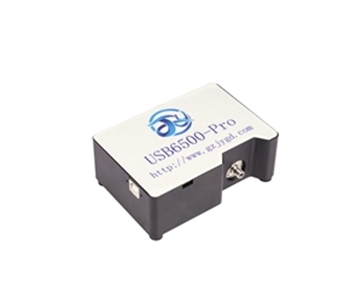
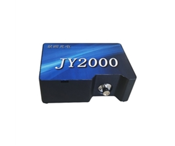
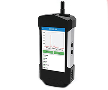
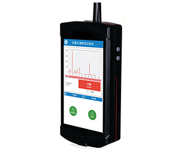
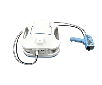
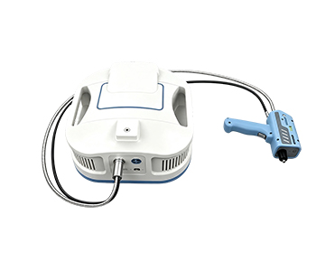
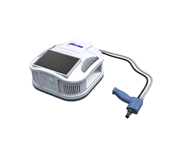
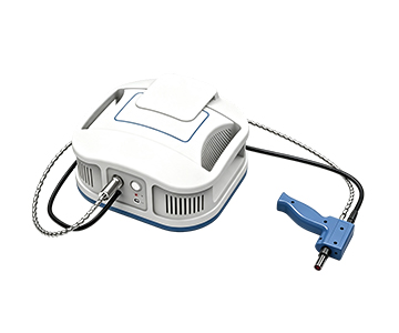
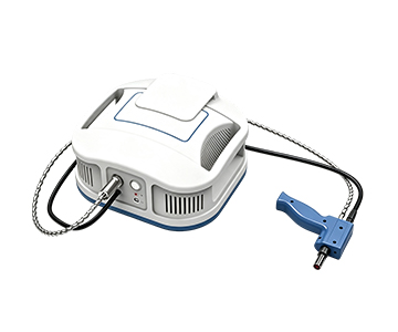
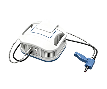
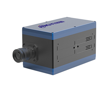
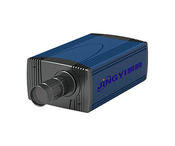
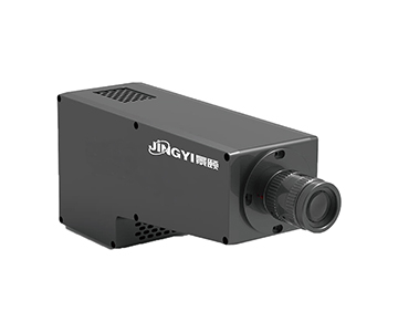
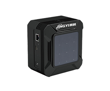
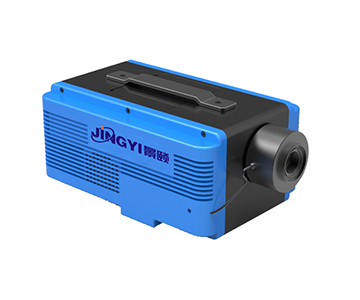
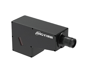
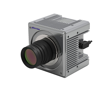
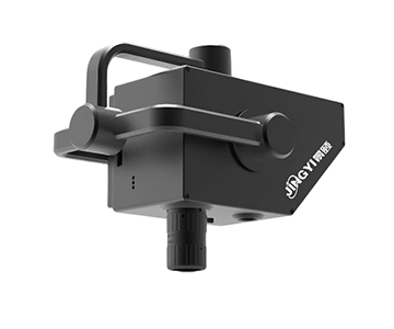
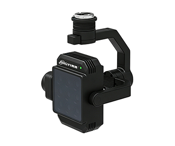
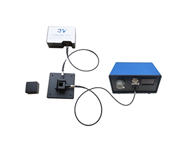
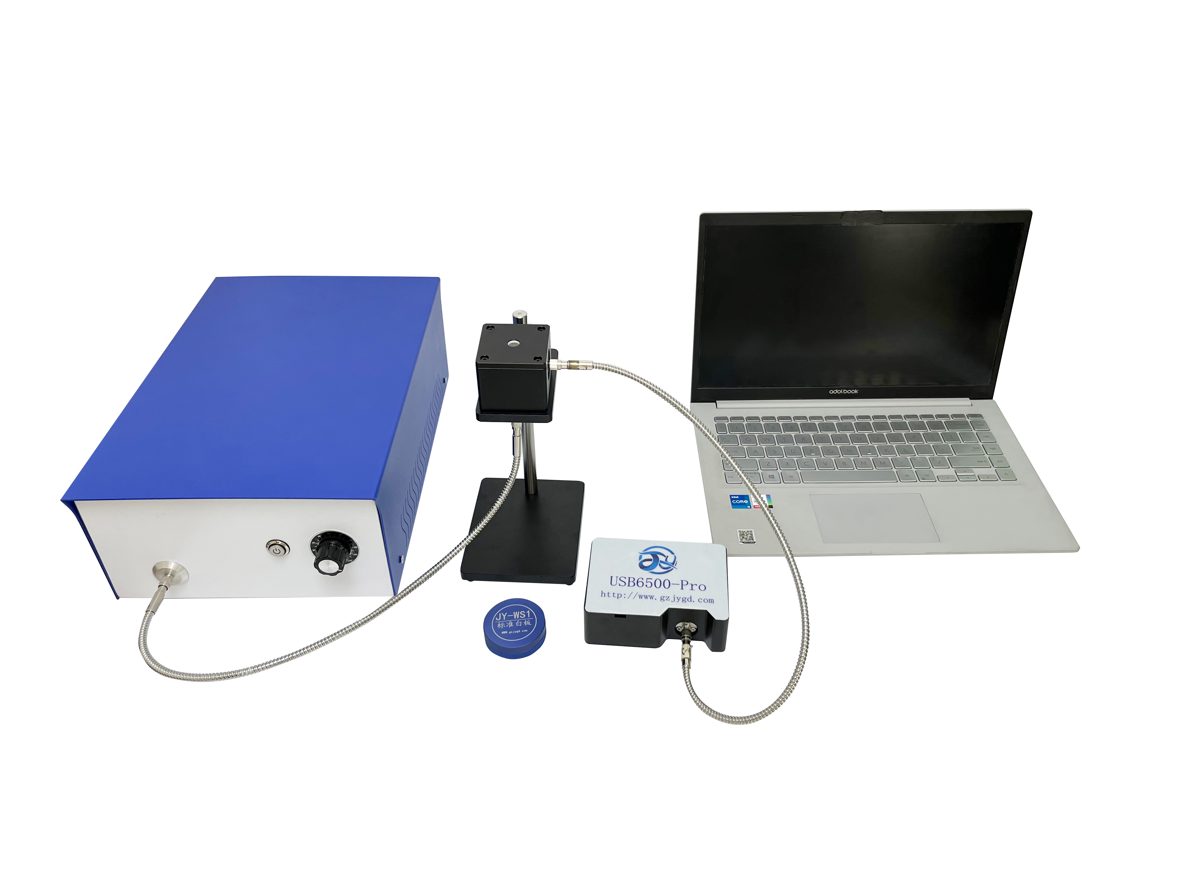
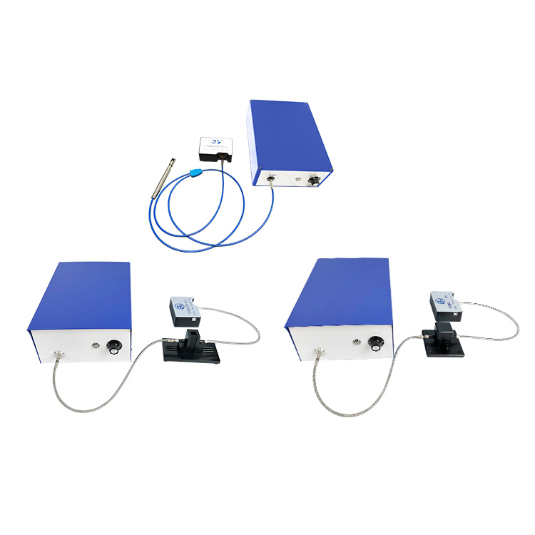
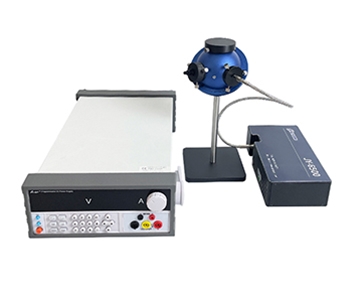
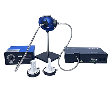
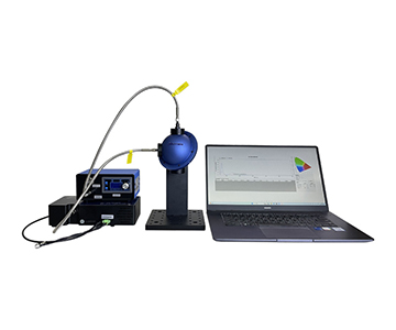
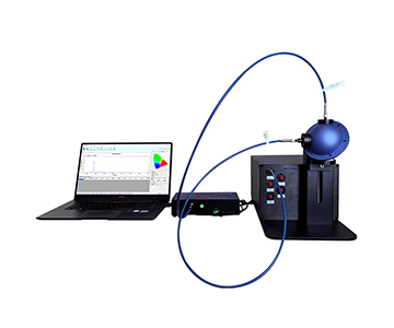
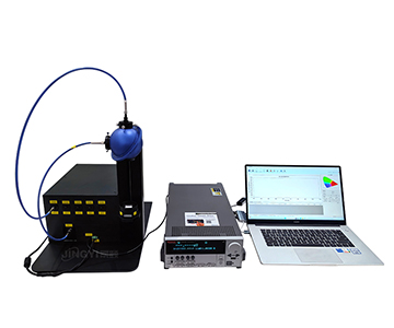
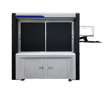
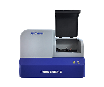
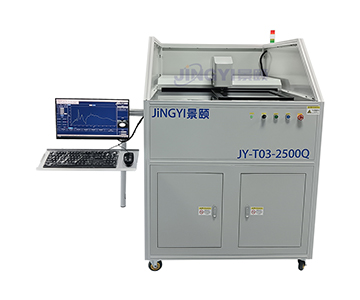
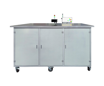
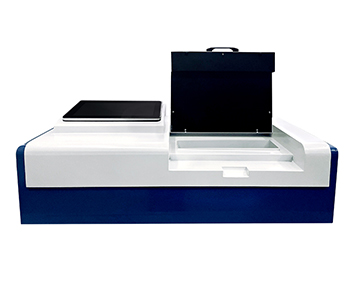
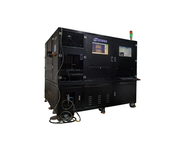
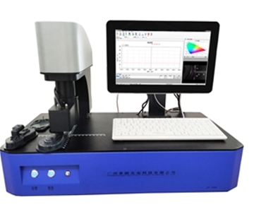
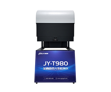
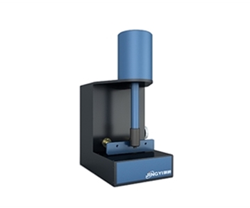
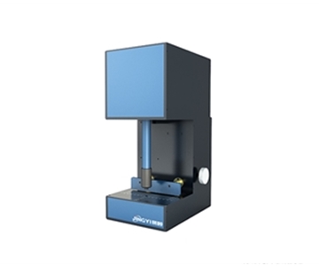
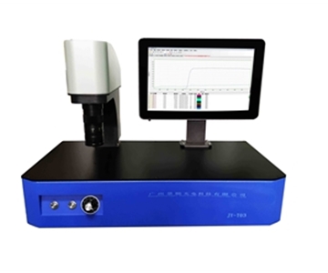
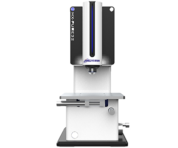
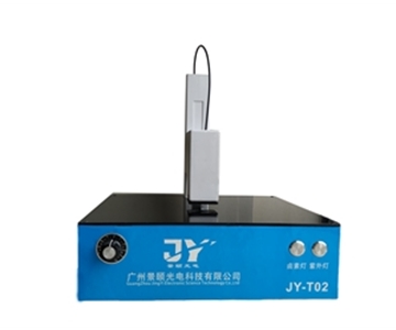
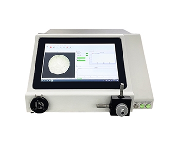
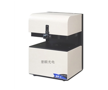
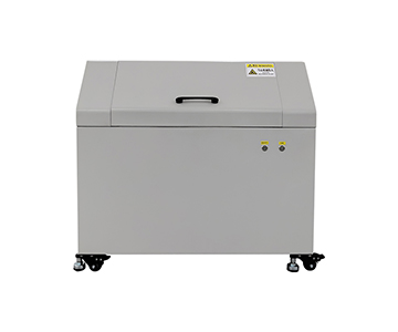
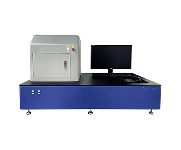
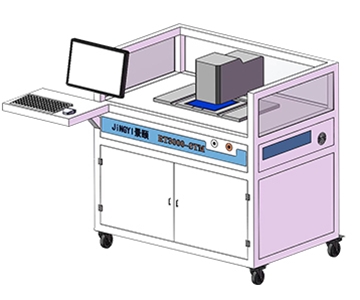
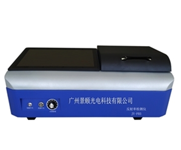
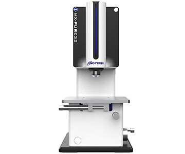
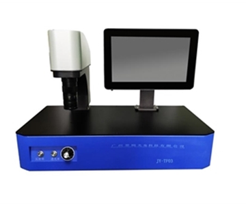
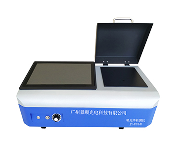
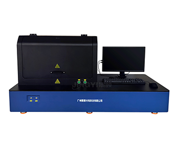
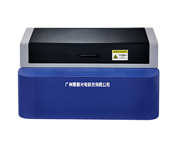
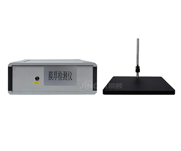
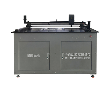
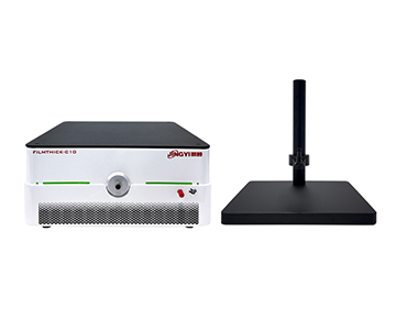
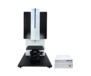
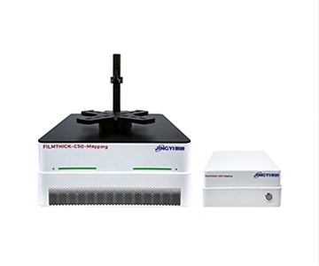
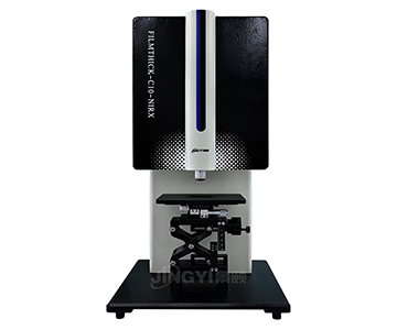
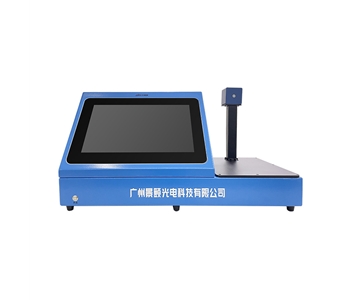
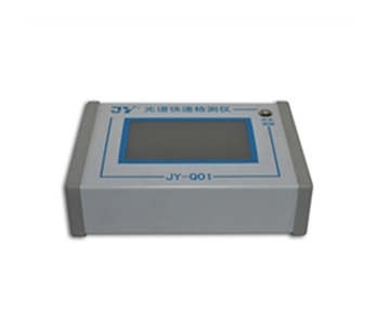
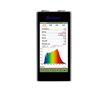
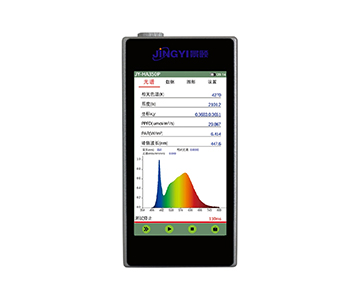
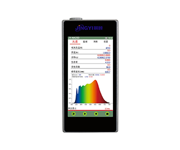
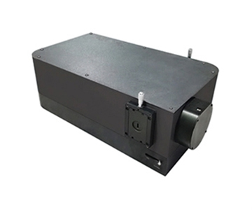
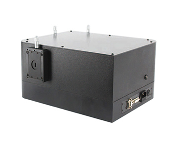
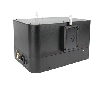
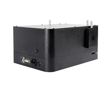
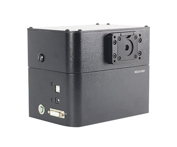
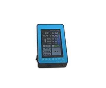
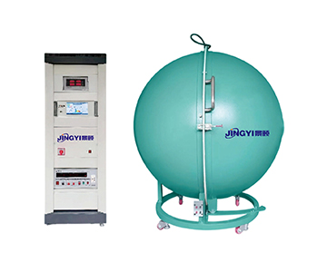
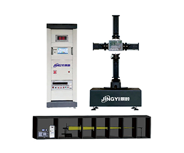
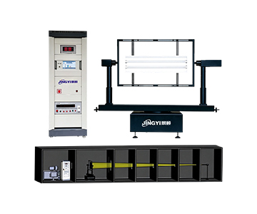
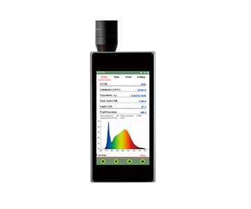
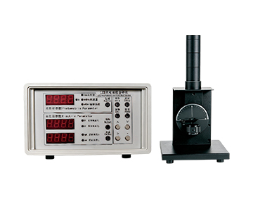
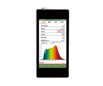
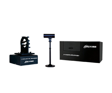
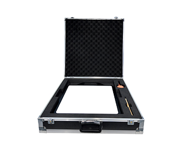
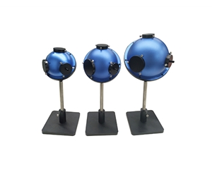
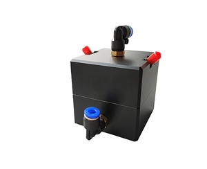
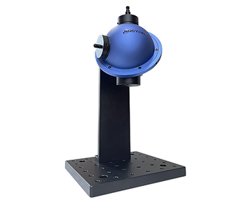
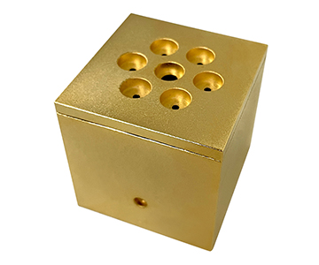
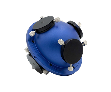
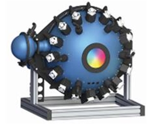
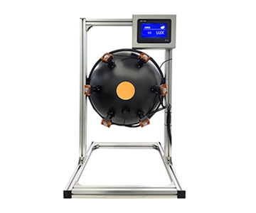
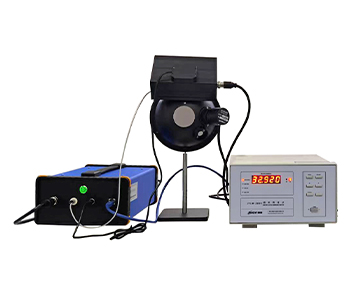
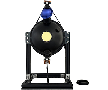
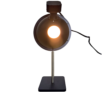
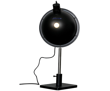
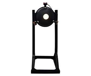
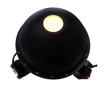
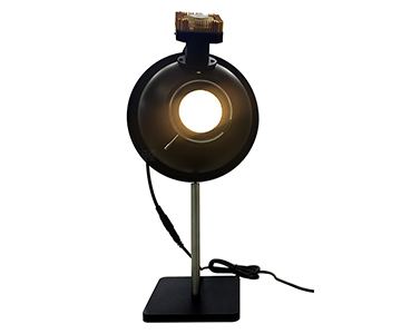
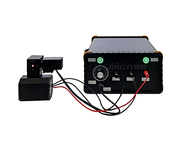
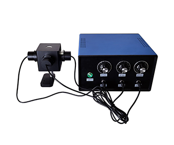
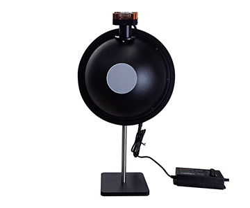
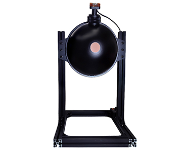
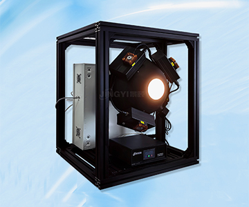
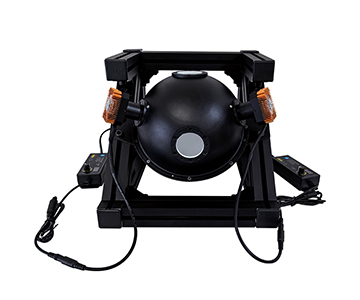
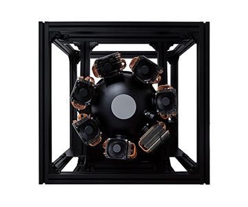
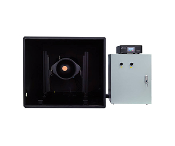
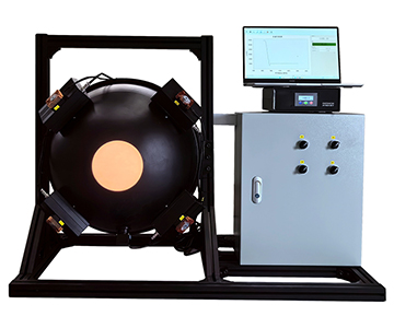
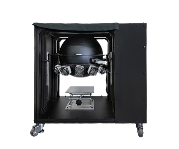
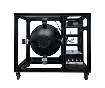
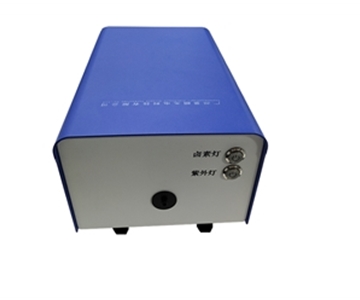
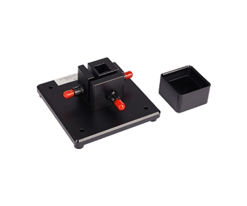
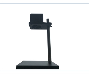
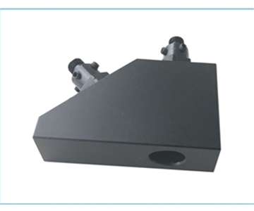
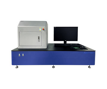
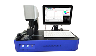
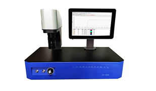
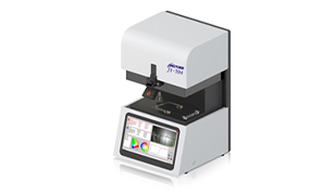
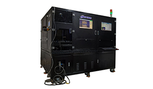
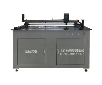
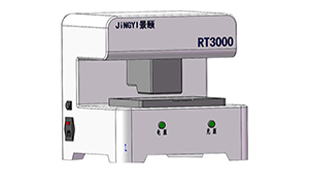
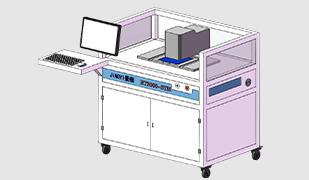
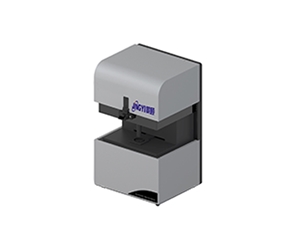
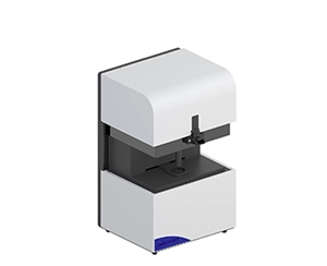
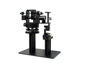
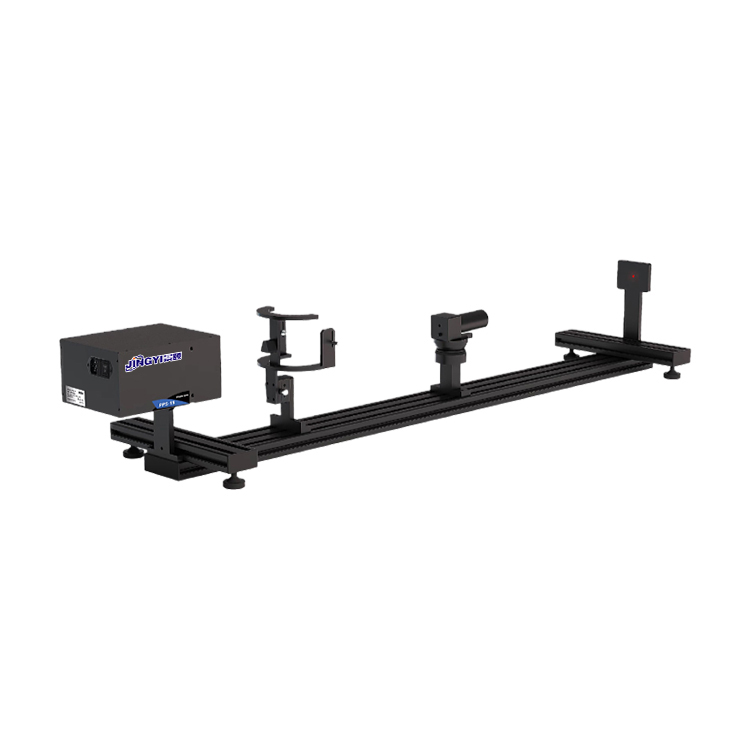
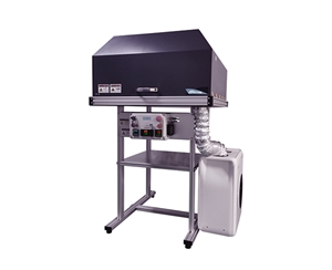
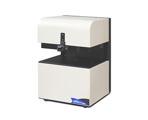
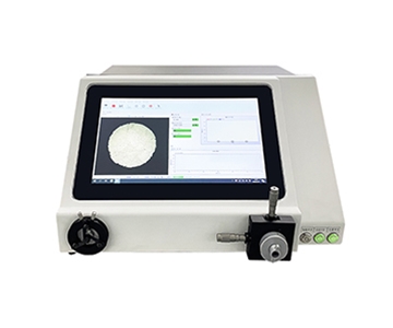
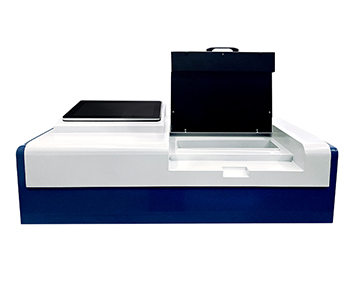
A Guangzhou‑based optoelectronics manufacturer founded in 2013 focuses on spectrometers, integrating spheres, and reflectivity systems, possessing vertical integration from optical components to analysis software. Its RMC series covers three forms: desktop sampling, single‑station production line, and multi‑station inline.
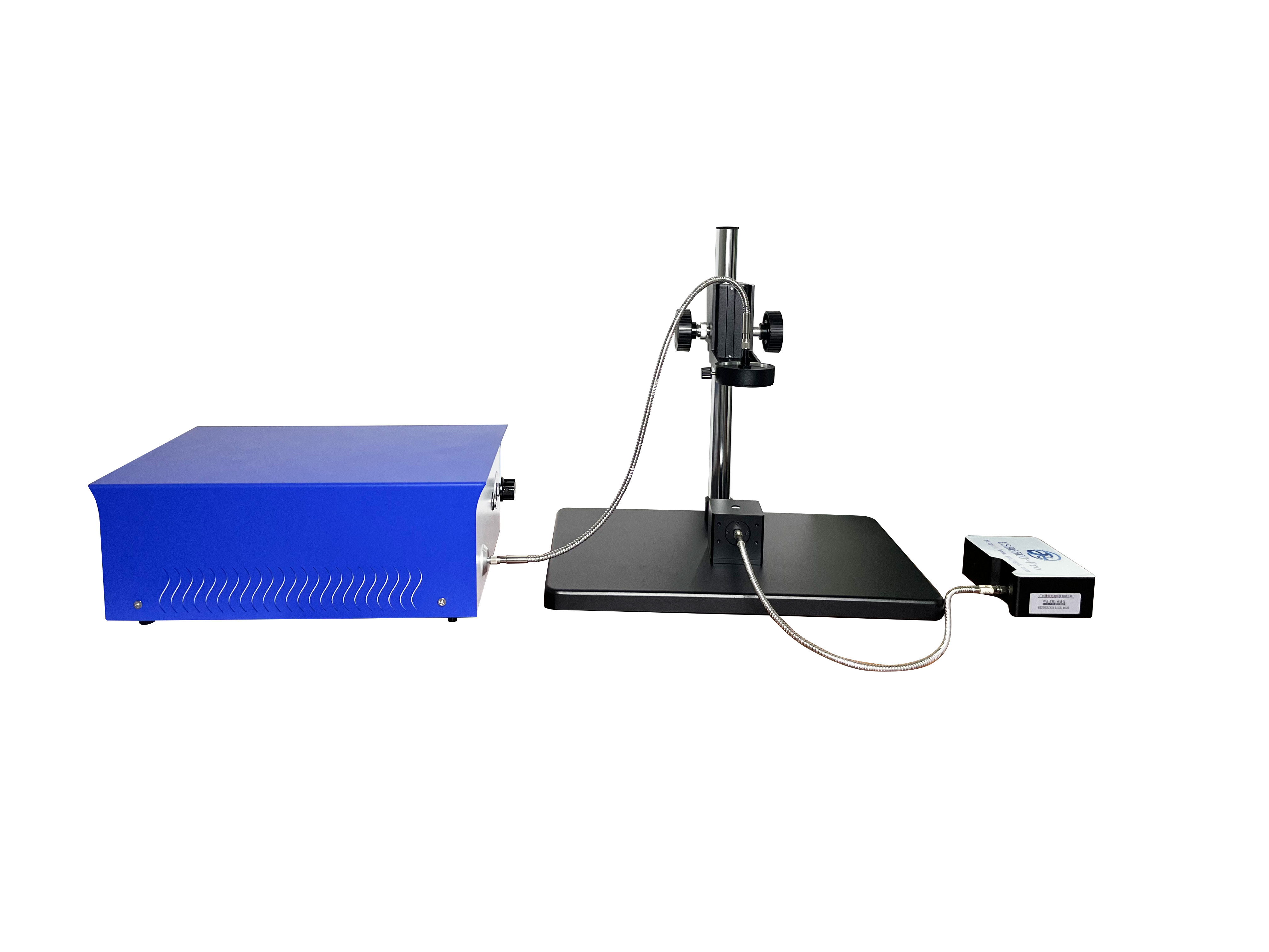
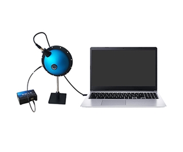
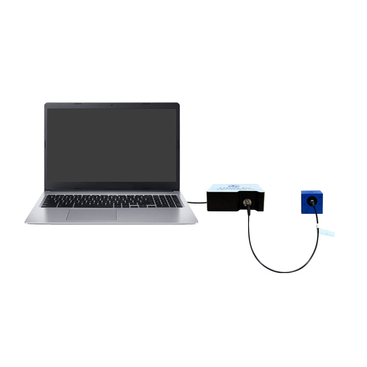
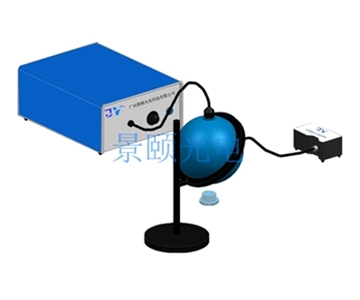
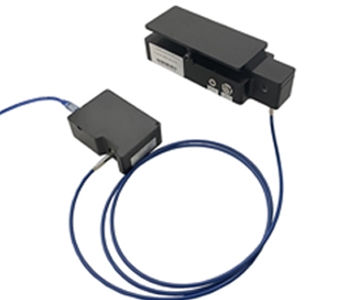
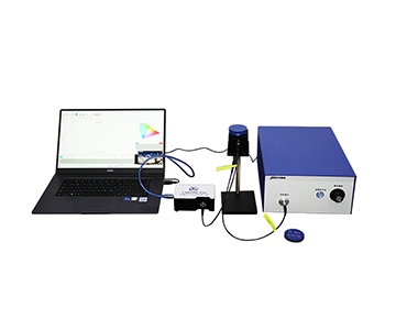
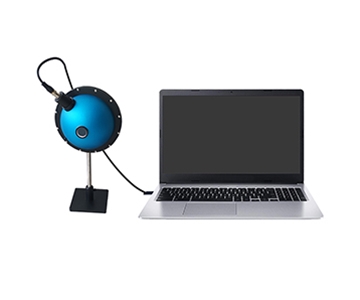
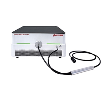
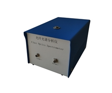
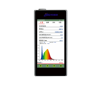
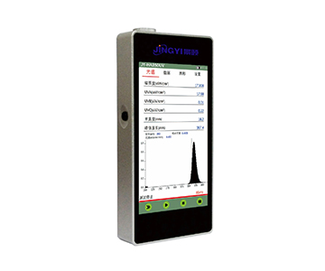
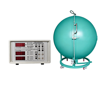
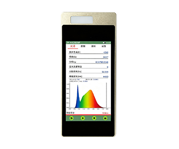
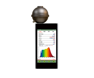
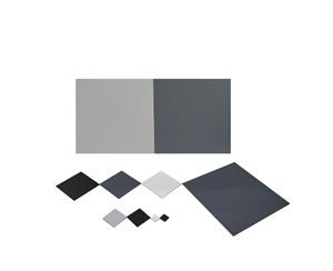
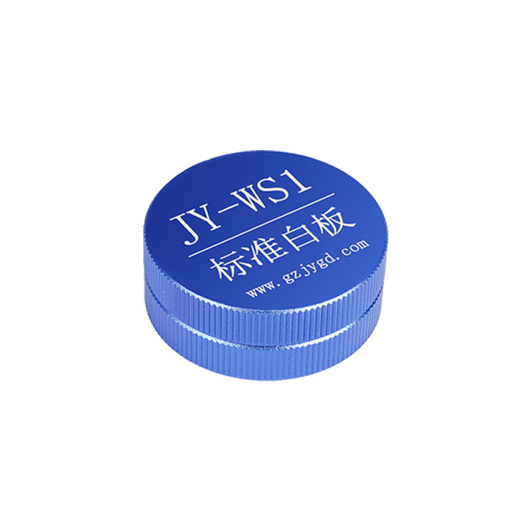
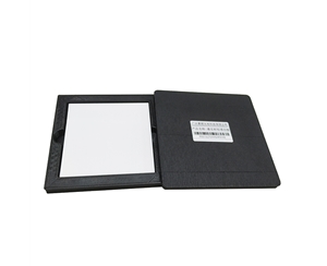
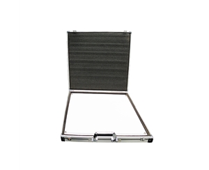
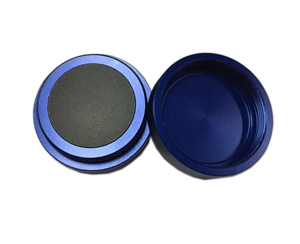
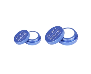
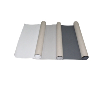
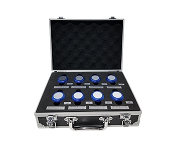
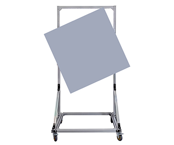
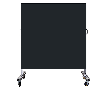
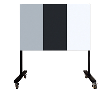
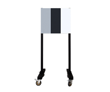
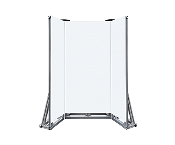
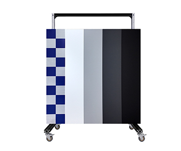
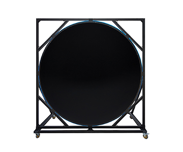
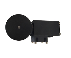
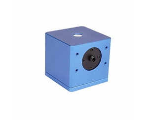
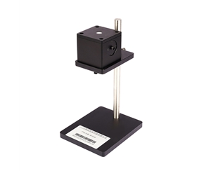
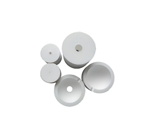
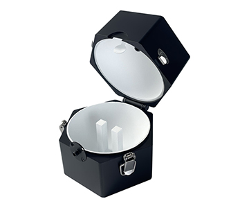
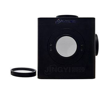
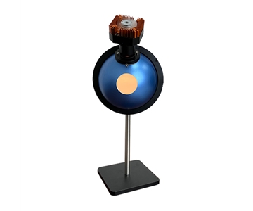
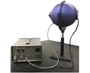
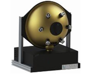
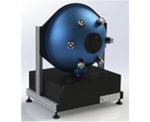
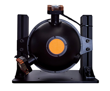
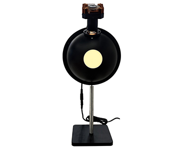
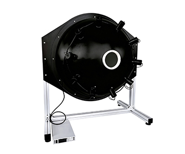
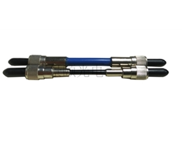
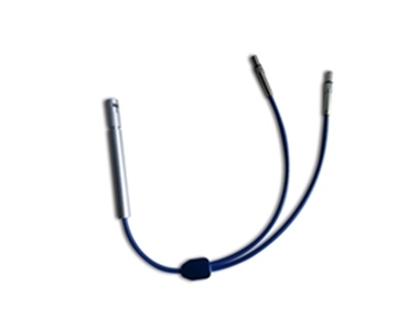
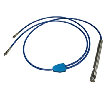
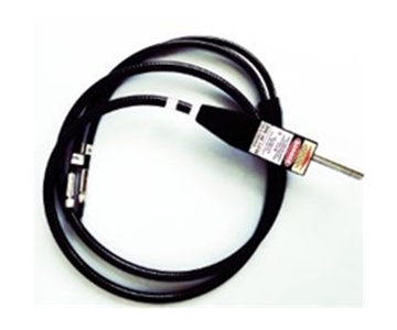
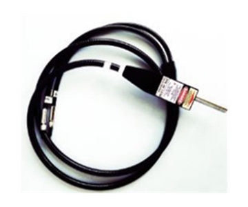
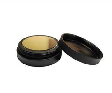
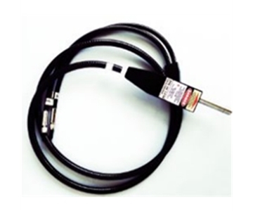
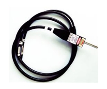
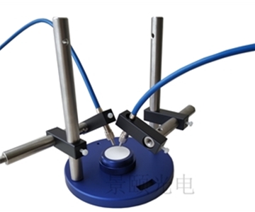
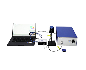
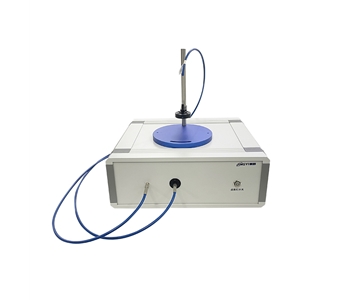
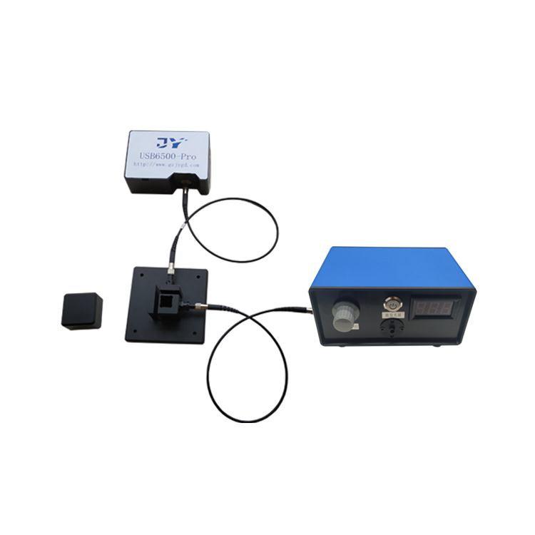
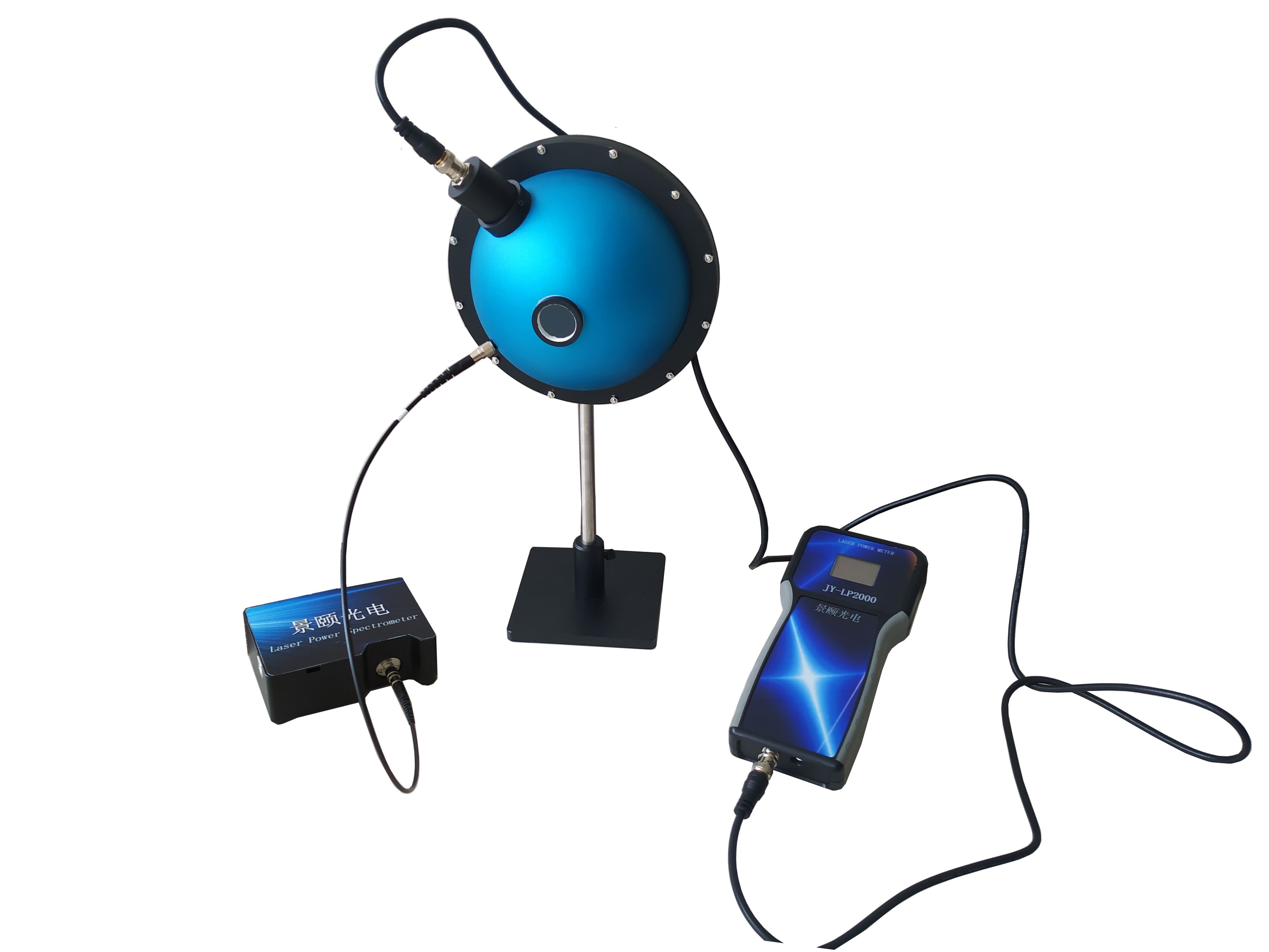
The RMC100 model adopts an integrating sphere with fiber spectrometer architecture, measuring aperture ≈9.5 mm (0.37 in), fiber length 3 m, equipped with a 27 mm PTFE reference whiteboard. As a drafting unit for GB/T 47066‑2026 (Plastics—Determination of total transmittance and total reflectance), the standard defines measurement methods and traceability requirements. Within this framework, the RMC100 achieves reflectivity accuracy better than 1%, wavelength coverage 400–1000 nm at 1 nm intervals.
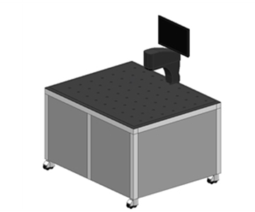
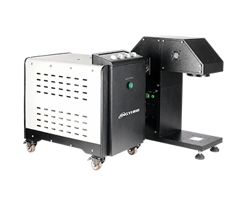
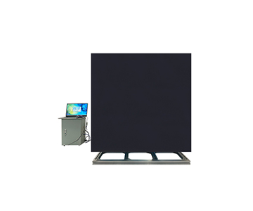
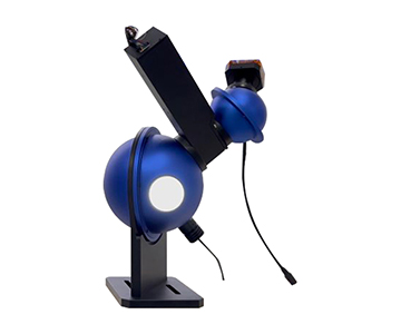
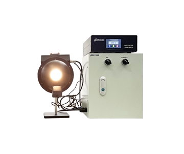
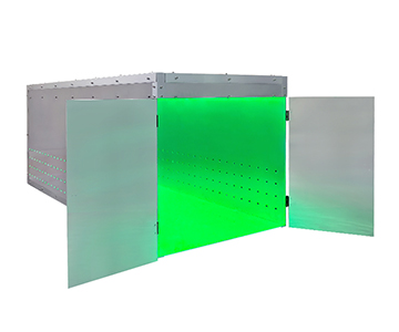
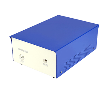
When a sample runs continuously in a ‑30°C cold chamber, 1 ms integration means capturing thousands of reflectivity jumps per second. For streaming media mirror powered low‑reflectivity judgment, halogen light intensity drift stays within ±0.5%/8 h, supporting eight‑hour continuous repeatability. The RMC200 integrates environmental chamber and main unit, operating without dropout at 65°C (149°F) on the high‑temperature side; optional light sensor and power modules simulate vehicle power supply and reverse signals.
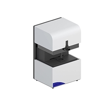
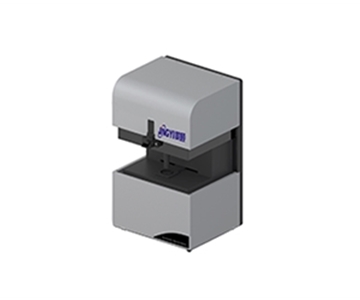
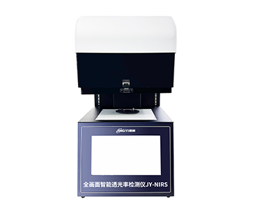
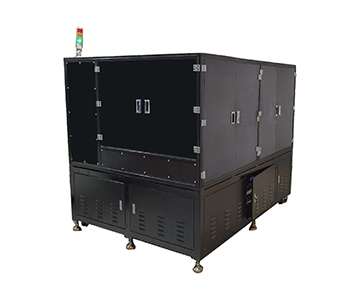
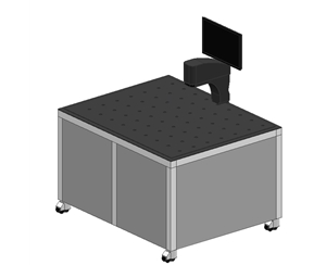
The RMC300 targets inline integration, supporting one‑object‑one‑code binding and system interfacing, with per‑piece records traceable by batch—performing notably in OEM final inspection stations.
Adaptation Scenarios and Boundaries
OEM laboratories, third‑party testing agencies requiring full‑project compliance data under high‑low temperature and customizable report formats, and mirror manufacturers undergoing certification conversion find lower integration cost here.
If the need is only single‑wavelength, small‑batch incoming visual inspection, the full‑range wide‑band and system‑level functions may exceed necessary configuration; a lightweight solution offers better overall cost.
Modular Optics and Flexible Production Line
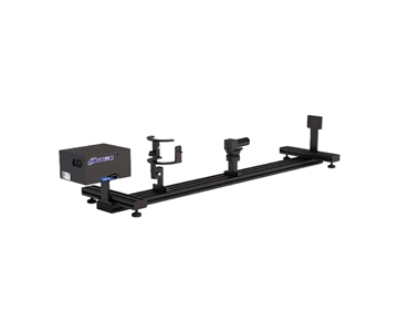
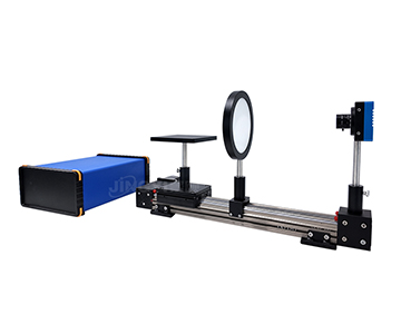
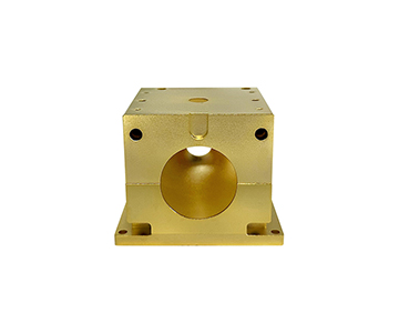
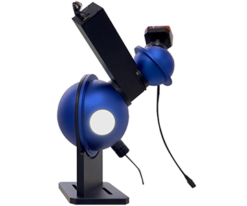
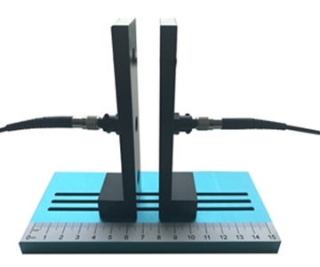
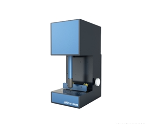
A specialist in optical probes and modular detection components offers the HX‑RM series, splitting fiber probes, integrating spheres, and light source drivers into independent modules. Users can freely swap multi‑angle incidence components according to curvature and installation angle.
In environmental reliability testing, the HX‑RM200 supports external temperature and humidity chambers. For asymmetric curved mirror samples, a probe offset of 0.37 mm causing spot misalignment is compensated by modular brackets—critical for batch sampling of multi‑curvature mirrors. Reflectivity test range covers full scale, integration time adjustable, adapting to different coating reflection intensities.
Adaptation Scenarios and Boundaries
Retrofit projects with existing temperature chambers and loading mechanisms that only lack an optical measurement core, or integrators needing to embed detection modules into self‑owned equipment, align well with this modular approach.
If a turnkey out‑of‑the‑box solution is desired, the modular route means partial mechanical and software integration must be completed in‑house; delivery responsibility boundaries need clarification upfront.
Traceable Measurement and High‑Precision Calibration
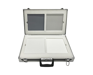
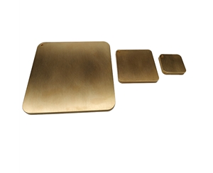
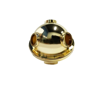
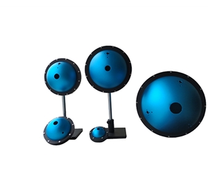
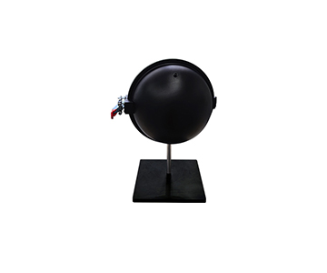
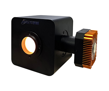
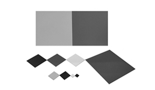
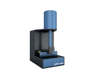
A precision measurement specialist emphasizes metrology traceability, focusing the GY‑RM series on reference plate verification, dark current subtraction, and long‑term stability. The device automatically subtracts ambient light before each test; integrating sphere coating reflectivity exceeds 99%, equipped with multi‑level reflectivity standard plate sets.
For arbitration comparisons or metrology accreditation, the GY‑RM150 offers wavelength resolution ≤1 nm, paired with annual calibration certificates to anchor reflectivity curves on a traceable chain. This capability earns high industry evaluation in automotive electronics R&D pre‑validation.
Adaptation Scenarios and Boundaries
Metrology institutes, OEM pre‑research institutes, and quality departments requiring long‑term preservation of test evidence chains value this route.
For high‑volume production final inspection with cycle time ≤20 seconds per piece, without selected automation extensions, manual intervention raises per‑piece cost, making it less suitable for high‑efficiency节拍.
Bentham Instruments: Laboratory‑Grade Spectral Heritage
The British company brings decades of accumulation in spectral measurement, with reflectivity systems characterized by highly stable monochromatic light paths and scientific‑grade detectors. In laboratories requiring ultra‑wide spectral scans and weak signal extraction, it provides detailed spectral profile reconstruction.
Light source stability and dark noise control are excellent, suitable for scenarios combining reflectivity research with material mechanism analysis; data comparability aligns smoothly with international literature.
Adaptation Scenarios and Boundaries
University optics labs, material‑level reflection mechanism research, and R&D projects needing data formats compatible with international publications tend toward this equipment.
Original factory delivery and spare parts are affected by cross‑border logistics; on‑site service response is less direct than local manufacturers. For high‑rhythm inline production inspection, overall ownership cost and maintenance timeliness require careful evaluation.
Instrument Systems GmbH: German Photoelectric Detection System
The German company offers a systematic product line in photoelectric detection and imaging luminance‑chromaticity analysis. Its rearview mirror approach leans toward comprehensive evaluation of brightness, chroma, and reflection characteristics, placing reflectivity into a “human visual perception” framework for joint acquisition.
The system can synchronously record luminance‑chromaticity changes during anti‑glare switching, providing rich physical dimensions for verification projects requiring subjective‑objective data closure.
Adaptation Scenarios and Boundaries
Luxury car mirror suppliers simultaneously concerned with subjective anti‑glare effect evaluation and objective data closure can use this system for multi‑physical‑quantity joint acquisition.
System complexity and software learning curve are high; for quality inspectors only wanting quick reflectivity readings, functional redundancy brings operational and training burdens.
Device Lifecycle from an Iteration Risk Perspective
Returning to the main thread of technical iteration risk: a senior validation engineer at a Tier‑1 mirror supplier discovered before an audit that legacy software had hardcoded judgment thresholds. When new standards changed night‑time reflectivity to a gradient judgment with time axis, firmware could not be upgraded, forcing a full replacement. Such incidents recur on three levels.
First, software evolvability. Reflectivity stability, power‑failure safety, reversing response time—all may be fine‑tuned with future standards. Analysis software must support custom judgment logic and report reconfiguration; otherwise, even expensive hardware becomes obsolete first.
Second, hardware expansion margin. When near‑infrared reflection characteristics are added for streaming mirror verification, whether the fiber spectrometer reserves band expansion slots and whether the integrating sphere can be replaced with wide‑band coating determines whether the device lasts five more years or is eliminated in two.
Third, data architecture. In inline monitoring, test dashboards, process capability analysis, and one‑object‑one‑code traceability cannot be patched in later with macros. During selection, clarify whether interfaces are open, if it can connect to quality systems, and whether the manufacturer can keep pace with standard updates.
Iteration risk redefines “buying equipment” from a one‑time purchase into “buying a continuously upgradable compliance capability.”
Solution Boundaries and Objective Review
No single device can cover all scenarios. Even a fully configured detection system will experience slow halogen light source attenuation under continuous high‑low temperature cycling; drift compensation algorithms only suppress it to an acceptable range. After introducing near‑infrared components, re‑verification with reference plates is required, adding an extra layer of uncertainty to the measurement chain compared to pure visible light.
Automated loading and multi‑station parallelism seem attractive, but when mirrors carry irregular brackets or wiring harnesses, mechanical positioning tolerances directly convert into reflectivity reading noise. Rather than stacking automation, it is better to first stabilize measurement repeatability at a semi‑automatic station.
These are common constraints of optical detection under automotive‑grade rigor, not defects of any single vendor. Acknowledging this prepares teams for audits and production reality.
Frequently Asked Questions
Q1: What spectral range is required for compliant rearview mirror reflectivity testing in 2026?
A1: Updated standards demand coverage from visible (400 nm) into near‑infrared, typically 400–1000 nm, to capture the full dynamic response of automatic dimming and streaming mirrors. Systems limited to single‑wavelength visible measurement will fail to record critical transition data.
Q2: How critical is millisecond‑level response time in reflectivity testers?
A2: Extremely critical. Anti‑glare mirrors must switch within hundreds of milliseconds after强光 exposure. A tester with 1 ms integration can capture thousands of data points per second, enabling accurate reconstruction of the reflectivity collapse‑and‑recovery curve required by regulations.
Q3: Can modular detection heads integrate with existing environmental chambers?
A3: Yes, certain modular systems support external temperature and humidity chambers. However, mechanical alignment tolerances must be tightly controlled; even 0.37 mm probe offset can cause spot misalignment, requiring compensatory brackets for multi‑curvature mirrors.
Q4: What traceability standards should a reflectivity tester meet for automotive certification?
A4: Equipment should provide calibration traceable to national metrology institutes (e.g., NIST in the US), with annual certificates and reference plates. Integration of dark current subtraction and ambient light compensation further strengthens data reliability for audit trails.
Q5: How can I independently verify a reflectivity tester’s performance before purchase?
A5: Conduct on‑site proof‑of‑concept testing using your own mirror samples across the full temperature range (‑30°C to +65°C). Compare results against a reference system traceable to NIST standards, and validate software’s ability to export raw time‑series data for third‑party analysis.
About This Guide
Data Sources
: Internal validation reports (n=47 mirror samples), UN ECE R46 regulation text, SAE J985 recommended practice, manufacturer published specifications (Jingyi Optoelectronics, Hangxin Optoelectronics, Guoyi Photonics, Bentham Instruments, Instrument Systems GmbH).
Author
: Cai Xiaodong, Senior Application Engineer, Jingyi Optoelectronics, 12 years in optical metrology for automotive electronics.
Disclosure
: Jingyi Optoelectronics manufactures reflectivity measurement systems. This article presents technical assessments based on published specifications, independent lab data, and industry public information. No compensation was received from third‑party brands mentioned.
Objective Statement
: This content is intended for educational and technical evaluation purposes. Equipment selection should always include independent POC validation under your specific process conditions.
Last Updated
: November 2026
For detailed specifications and application notes on rearview mirror reflectivity testers, search "Jingyi Optoelectronics rearview mirror reflectivity tester" or visit our technical library.