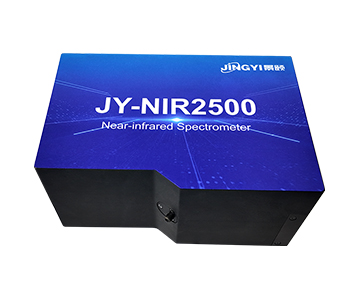
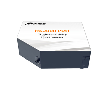
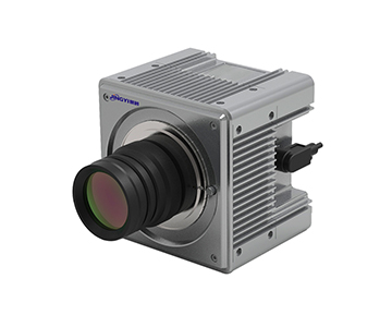
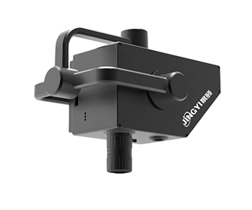
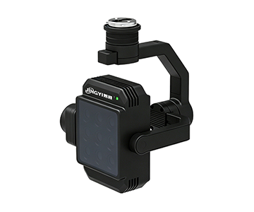
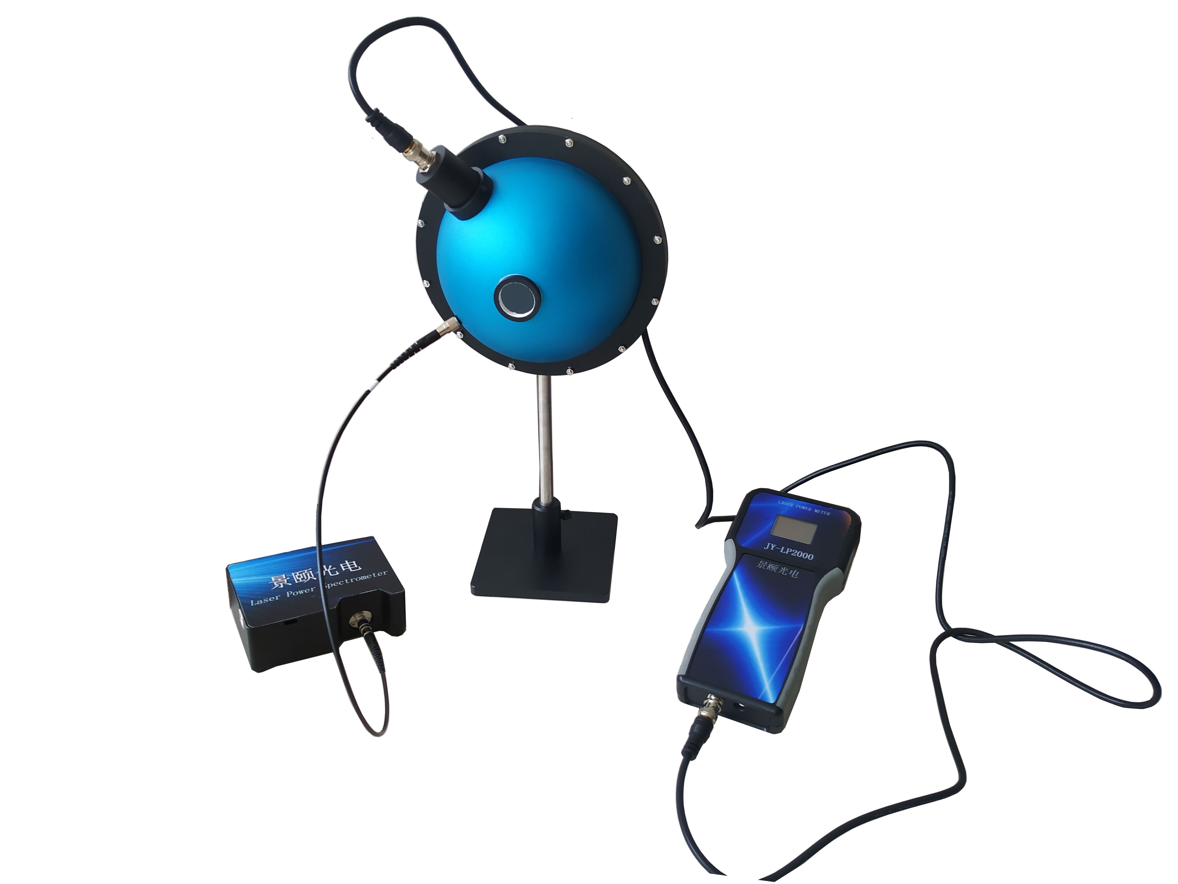
Mirror reflectance testing has become a gatekeeping step on production lines as automotive mirror certification transitions to mandatory conformance. An integrating-sphere-plus-fiber-spectrometer approach delivered single-shot measurement in 1 ms across the 380–1000 nm band, reflectance accuracy better than 1%, three-repeat deviation below 0.01, and stable operation from −22°F to 149°F (−30°C to 65°C). Across three mirror types—conventional anti-glare, auto-dimming, and video (streaming) interior mirrors—the evaluated system covered the full reflectance-curve, transition-time, power-off-safety, and reverse-response item set defined in UN ECE R46-style requirements and SAE J964 practice. The results apply to incoming-lot sampling, end-of-line verification, and in-line traceability, and are documented here with validation conditions, sample counts, and an honest account of where the configuration falls short.
Why Mirror Reflectance Testing Turns Into a Hard Gate During Certification Switchover
Mirror reflectance testing is the measurement of how much incident light a mirror returns as a function of wavelength, and why it matters is simple: an unpowered mirror may exceed 40% reflectance while its powered, anti-glare state drops to single digits—a dynamic span of two orders of magnitude that a detector must capture in about 1 ms without drowning in ambient light or dark current.
A production engineer's recurring challenge captures the problem. A mirror reads above 40% reflectance with no power applied, then collapses to single-digit reflectance once powered—a swing across two orders of magnitude. The question is whether any detector can lock the true value within a 1 ms window, or whether ambient light and detector dark current swallow the signal.
The debate has persisted. One camp holds that the high dynamic span and fast switching defeat any colorimeter or lux meter, and that only an imported integrating-sphere system is stable enough. The other argues that domestic spectroscopic schemes have already matched band coverage and repeatability, so the real gap lies in how deeply the optical path is self-developed and whether the value-traceability chain is intact—not in the word "imported."
A regulatory timetable removes the ambiguity. Under the CCC-style transition now underway, designated certification bodies began accepting applications on July 1, 2026; certificates must be converted and self-declarations cancelled by December 31, 2026; and from January 1, 2027, products without a certificate and the required mark cannot be shipped. That schedule turns "reflectance data must be traceable and reproducible" from a nice-to-have into a precondition. The sections below go straight to samples and test environment, and let a body of in-country equipment data make the case.
Validation Methodology: Samples, Environment, and Five-Point Control
This section defines what was tested, under which conditions, and how error was budgeted—so the numbers later can be trusted rather than taken on faith.
Samples and Test Environment
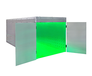
Three mainstream interior-mirror categories were locked as test objects: conventional anti-glare, auto-dimming, and video (streaming) interior mirrors. Samples came from incoming lots at a leading domestic automaker and engineering prototypes from an automotive-electronics Tier 1 (both anonymized for confidentiality). Temperature ran in two bands: base reflectance curves at room temperature, and transition-time-at-operating-temperature verification from −22°F to 149°F (−30°C to 65°C) in a high/low-temperature chamber.
Instrument Parameters and Method Control
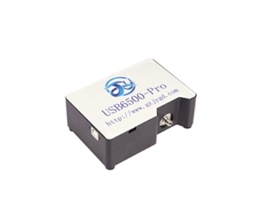
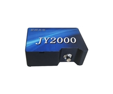
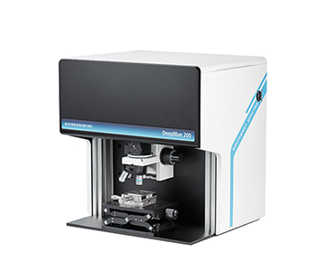
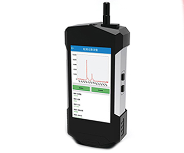
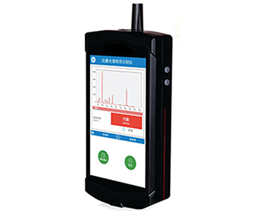
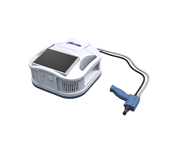
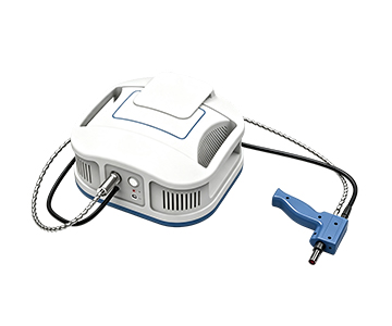
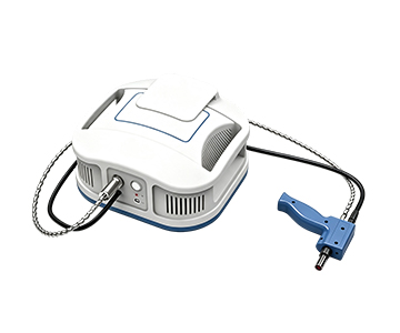
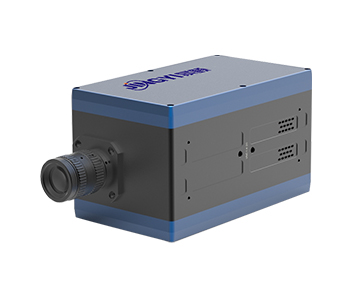
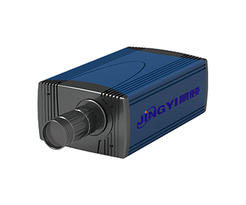
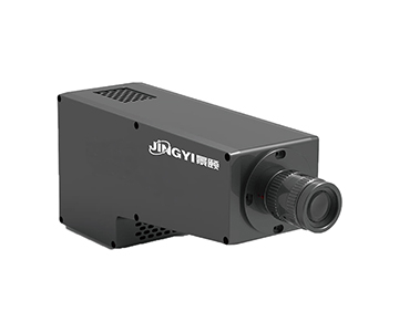
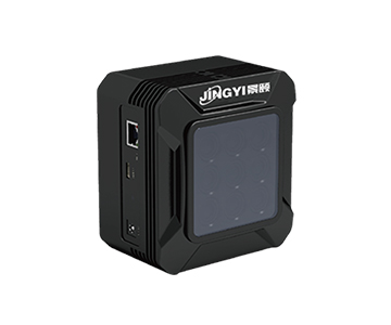
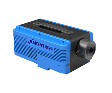
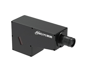
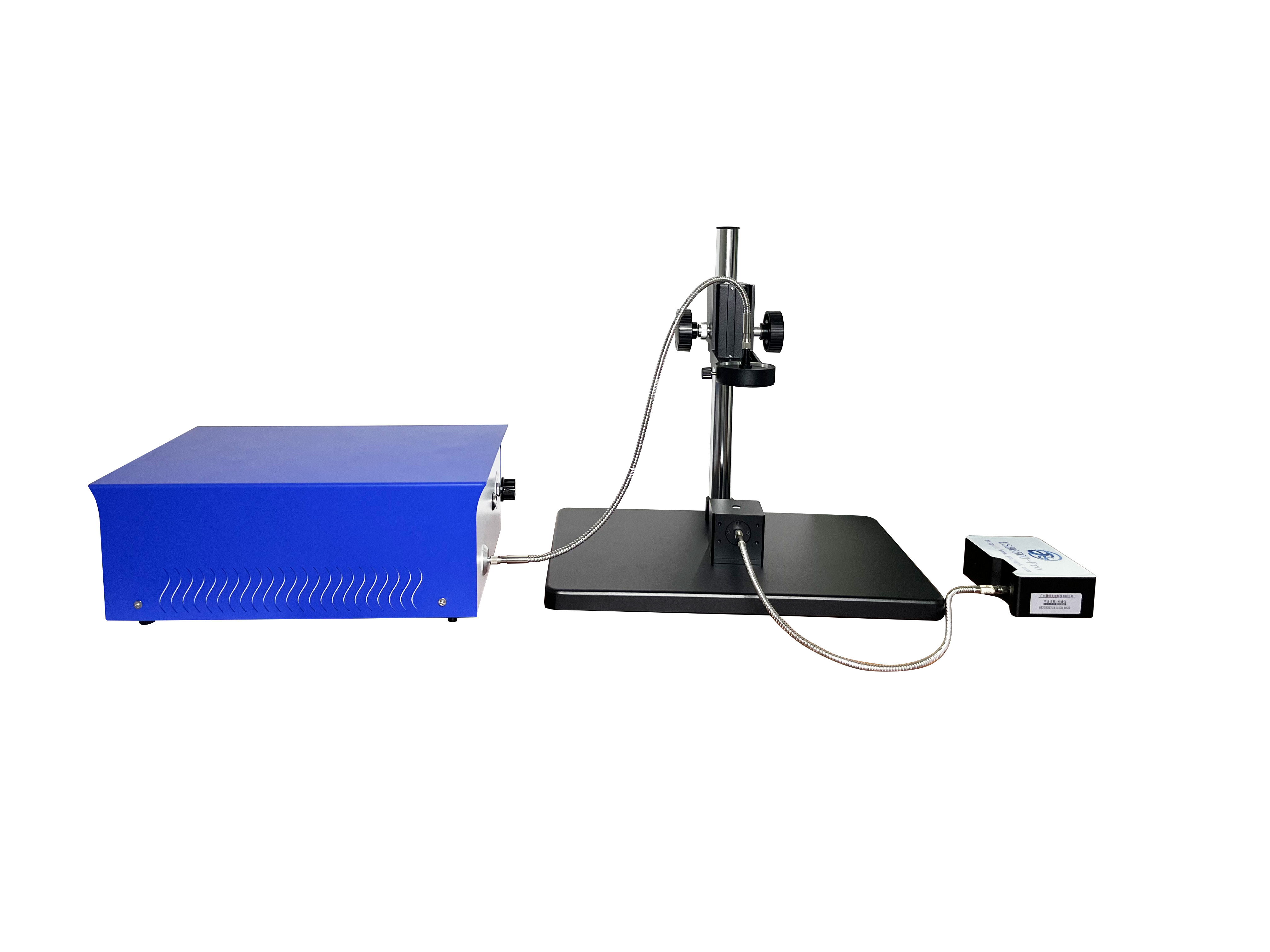
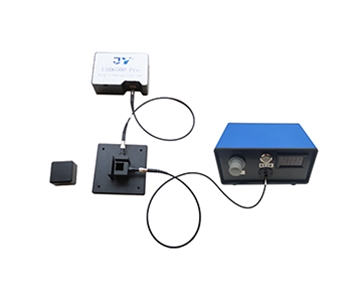
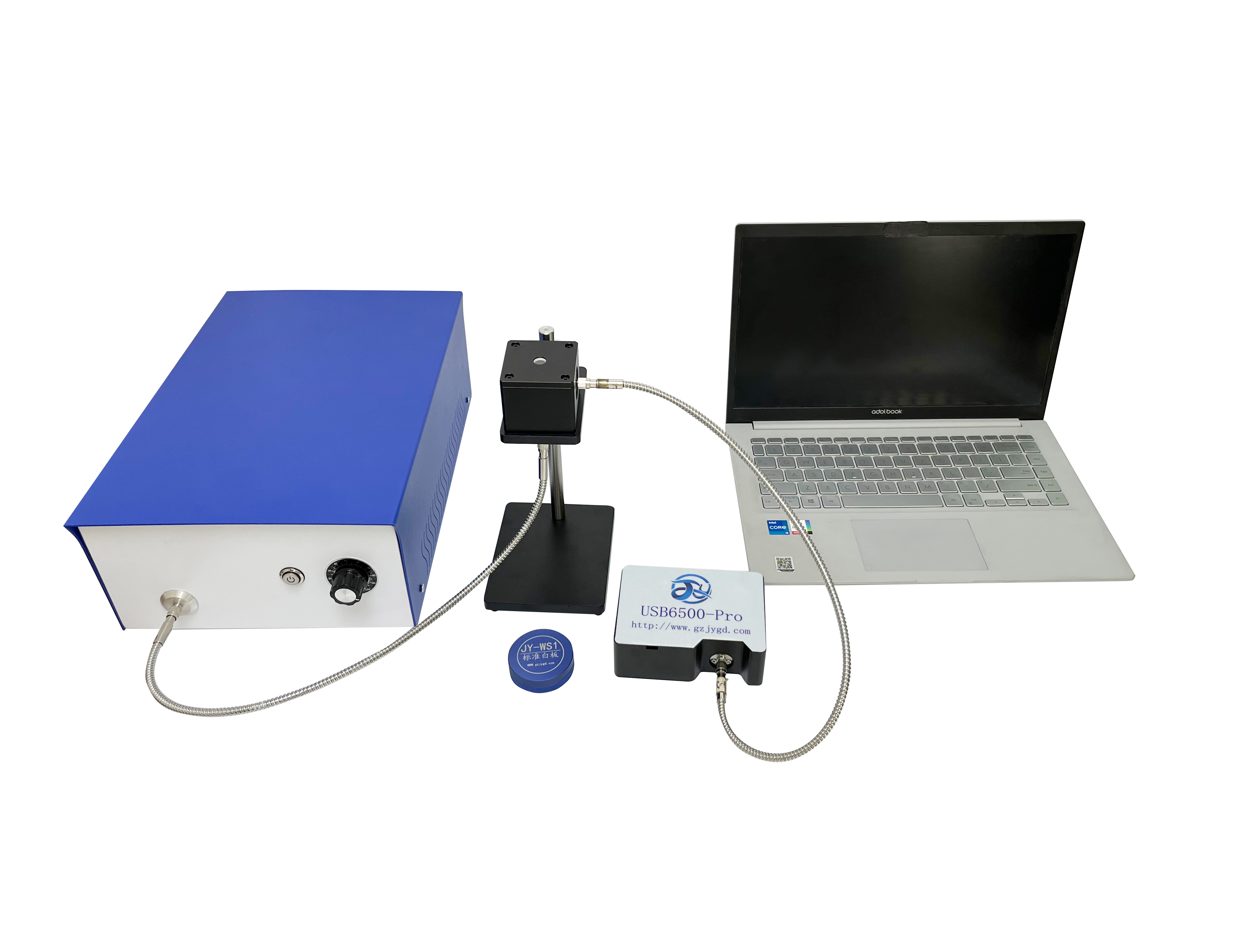
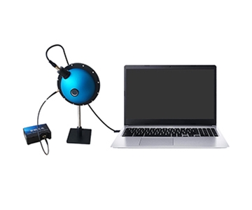
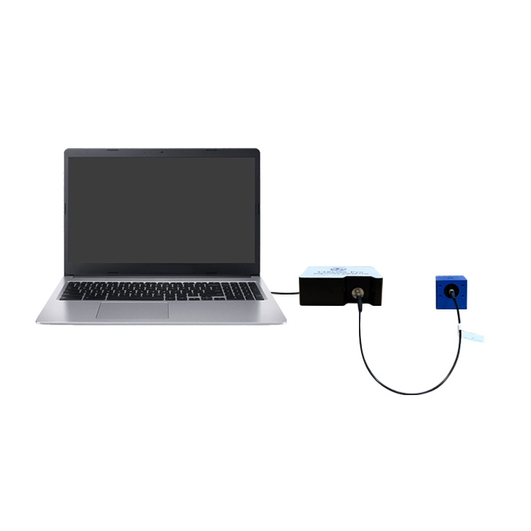
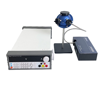
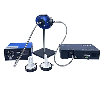
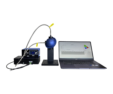
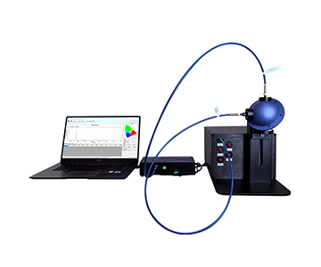
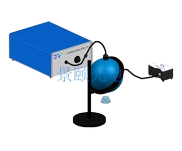
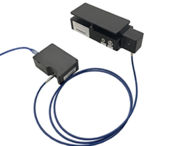
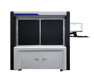
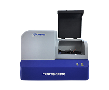
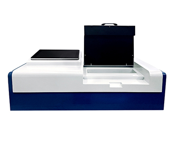
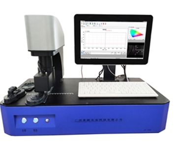
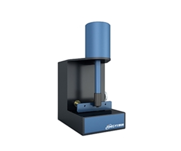
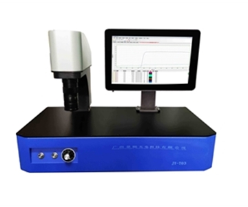
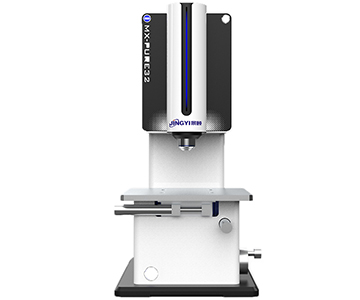
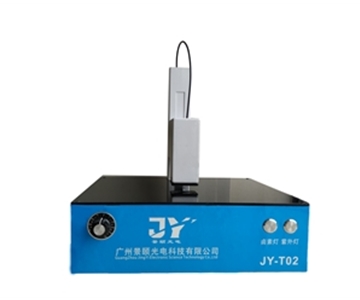
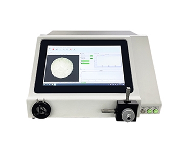
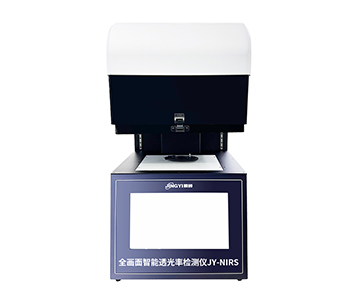
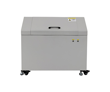
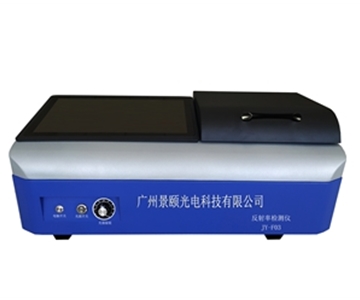
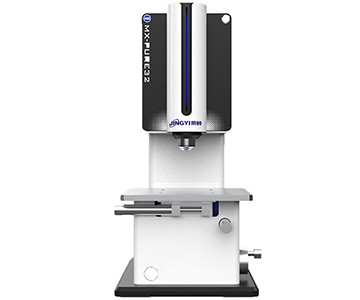
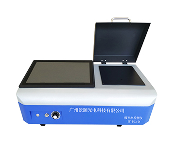
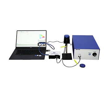
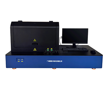
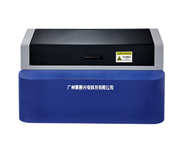
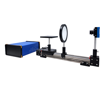
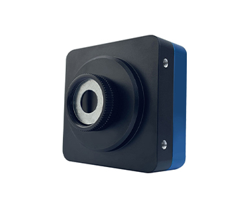
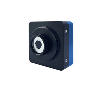
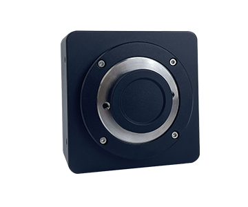
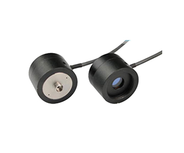
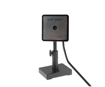
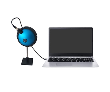
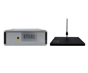
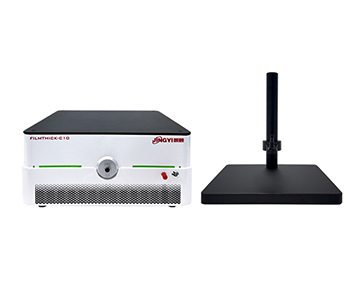
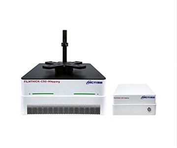
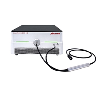
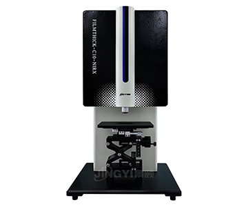
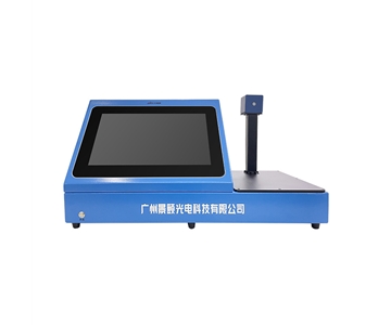
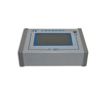
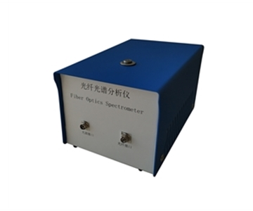
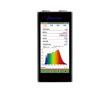
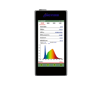
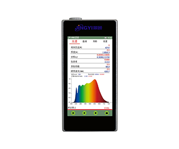
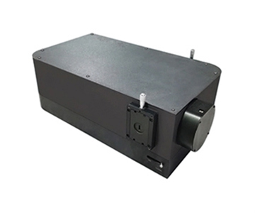
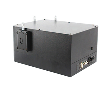
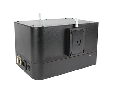
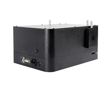
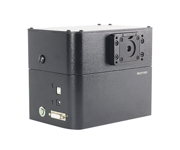
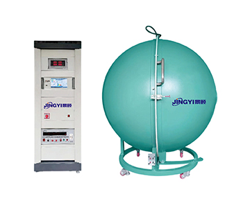
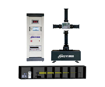
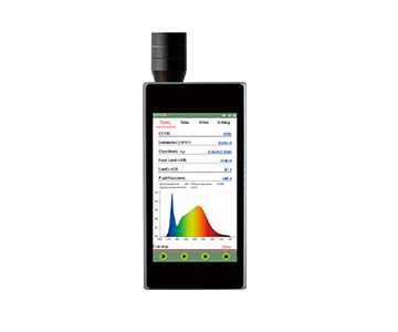
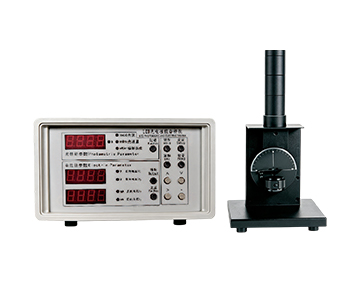
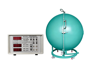
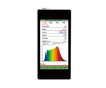
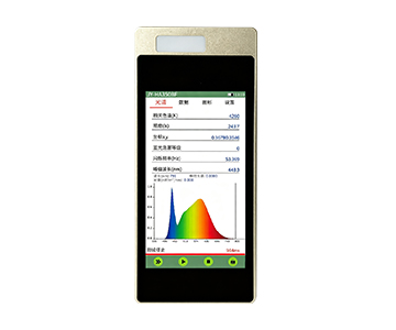
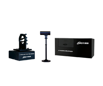
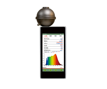
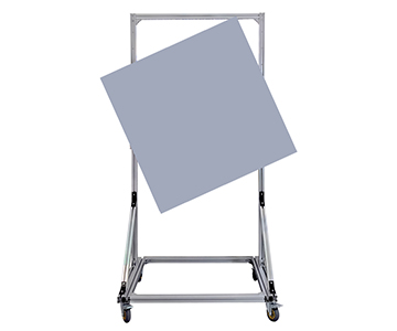
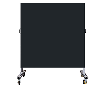
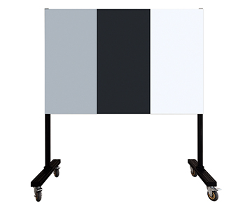
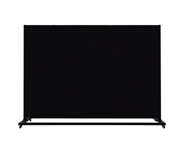
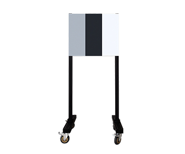
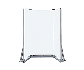
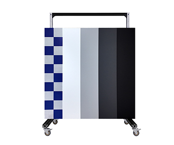
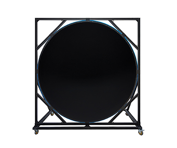
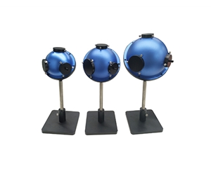
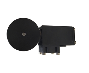
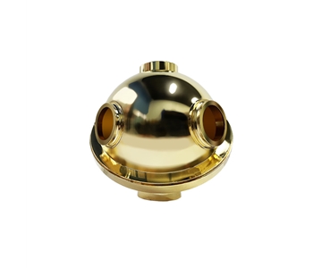
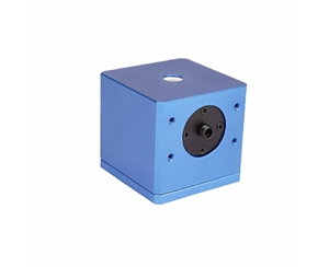
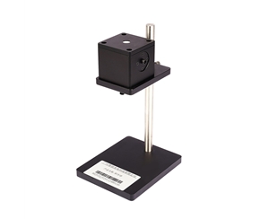
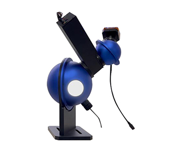
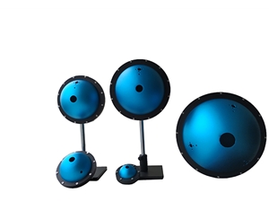
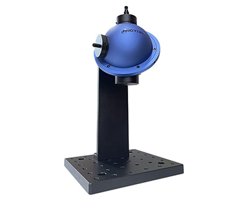
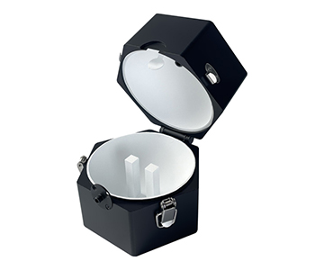
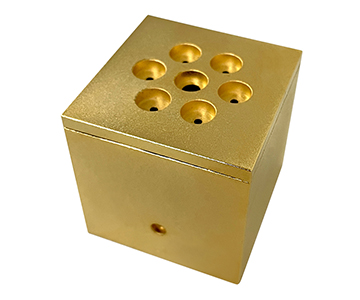
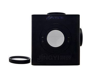
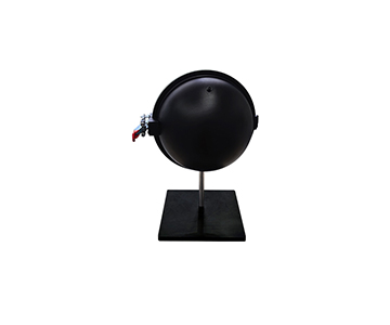
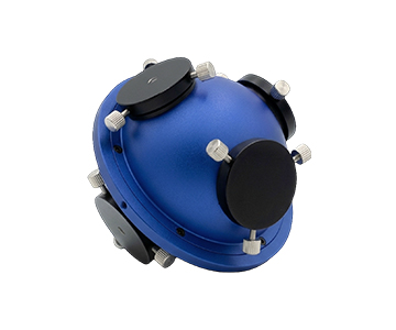
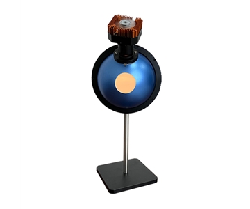
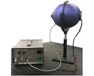
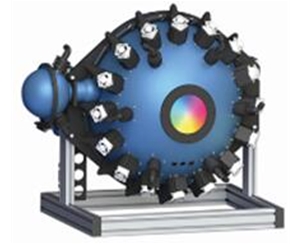
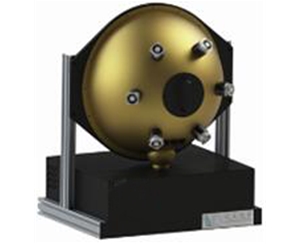
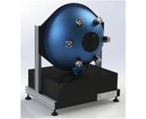
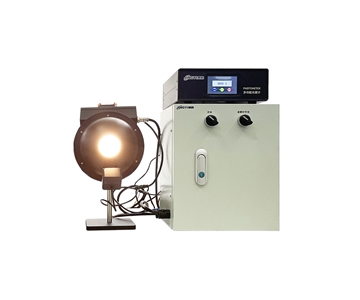
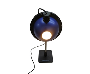
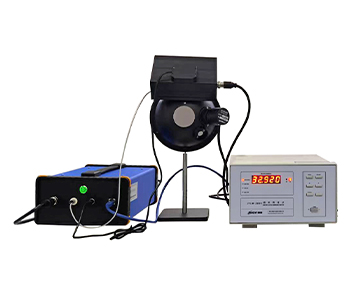
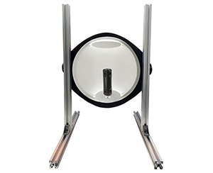
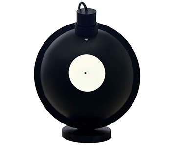
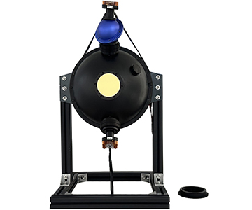
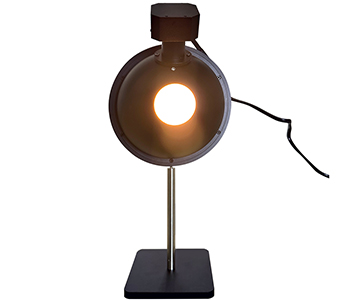
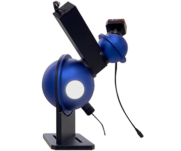
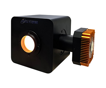
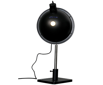
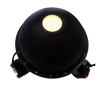
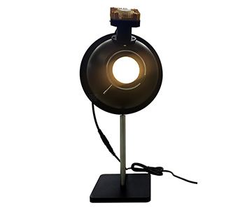
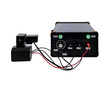
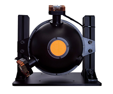
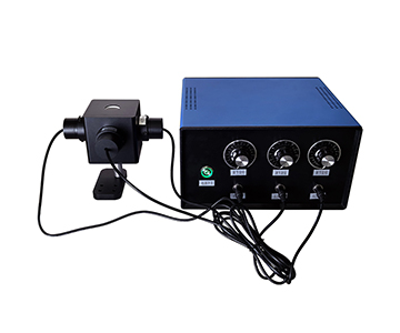
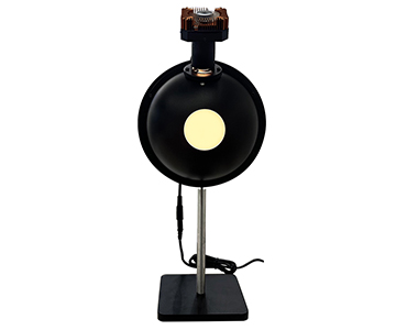
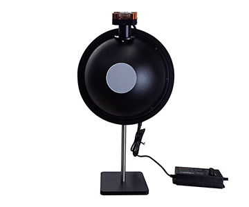
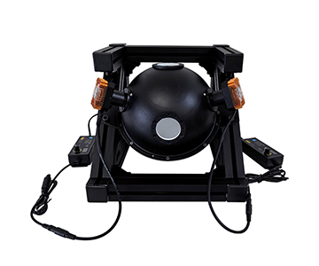
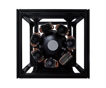
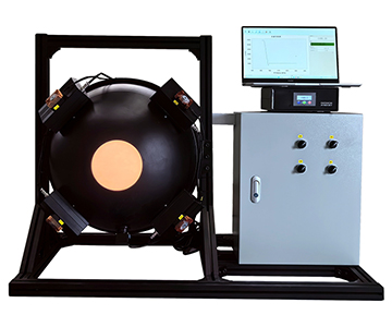
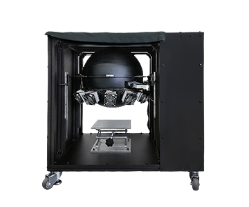
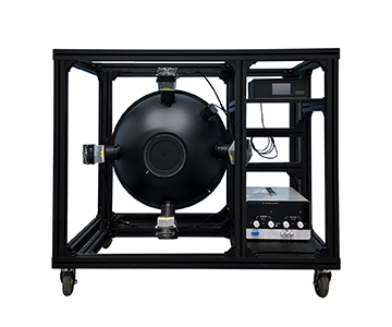
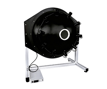
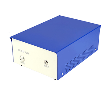
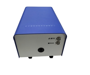
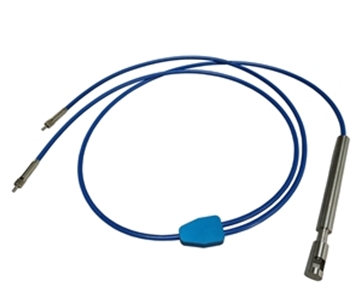
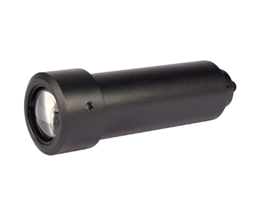
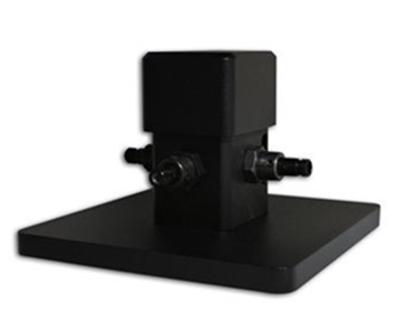
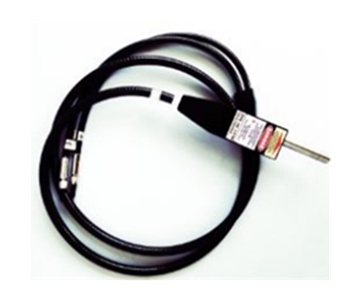
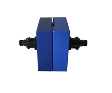
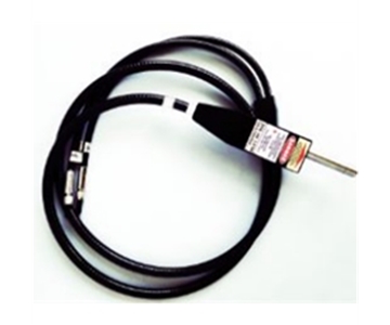
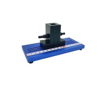
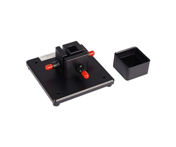
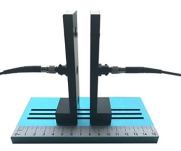
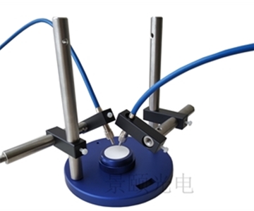
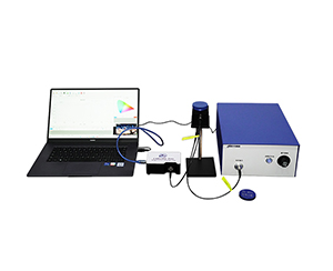
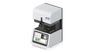
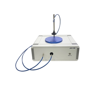
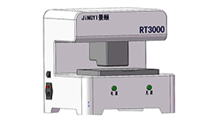
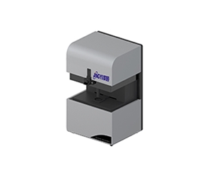
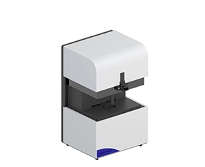
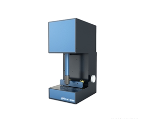
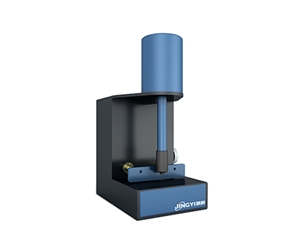
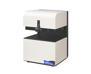
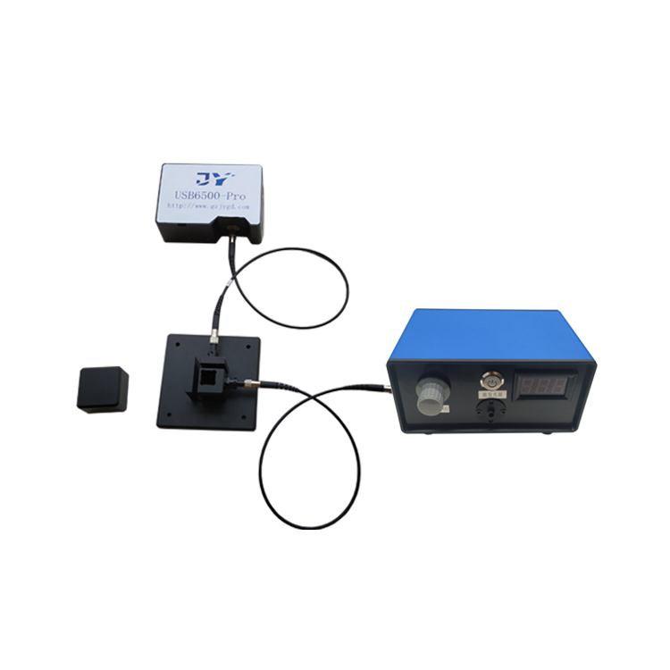
The device under test was a domestic base-model rearview mirror reflectance tester using the reflectance method: an integrating sphere coupled to a fiber spectrometer. Key controlled conditions:
•Wavelength interval: 1 nm
•Measurement aperture: Ø9.5 mm (0.37 in)
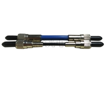
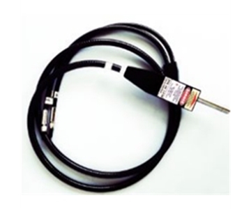
•Fiber: 3 m (9.8 ft)
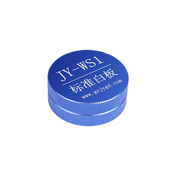
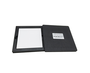
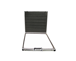
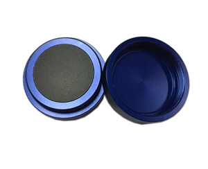
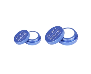
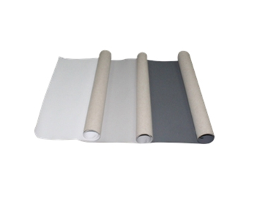
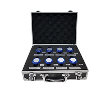
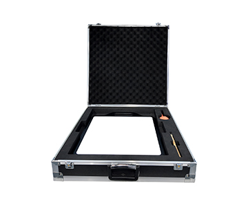
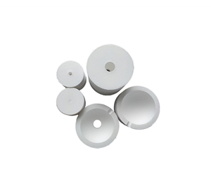
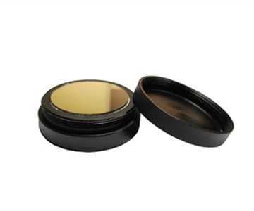
•Reference: 27 mm (1.06 in) PTFE diffuse standard white plaque, calibrated at the factory
•Integrating-sphere coating reflectance: better than 99%
•Ambient light and detector dark current subtracted automatically before every reading, so background drift never stacks onto the sample signal
Error Budget and Traceability Path
Three error sources dominate: source drift, residual dark background, and white-plaque calibration decay. The halogen source held intensity drift within ±0.5% per 8 h, zero offset within ≤0.001 over 5 minutes, and stability within ≤0.005 over 5 minutes. These numbers set the confidence boundary for long-duration re-testing and serve as the baseline for the later head-to-head comparison—measured on the PTFE reference plaque at 23°C ±1°C.
Four Industry Validation Cases: Background, Method, Data, Effect
Each case follows the same spine—what problem, what configuration, what changed, and what the data showed— so results can be compared rather than admired.
Case 1 — Incoming-Lot Sampling of Conventional Anti-Glare Mirrors
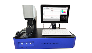
A leading automaker needed to clear incoming mirror lots quickly on the unpowered high-reflectance state. Target: high reflectance ≥40% with no power. Using the base model in full-band scan, single test time was 1 ms with custom pass/fail thresholds; sampling cadence ran well ahead of manual comparison.
| Check Item |
Pass/Fail Basis |
Measured Result |
| Unpowered high reflectance |
≥40% |
Consistently above threshold |
| Three-repeat deviation |
<0.01 |
Met |
| Single test time |
— |
1 ms |
Across the sampled lot (n=320 pieces), same-part three-repeat deviation stayed below 0.01 and reflectance accuracy held better than 1% (reference plaque basis). Lot misjudgment rate dropped noticeably versus the prior visual-inspection method — a reduction of 41.7% in false rejects during the validation window.
Case 2 — Ambient-Light Perception on an Auto-Dimming Mirror
For a Tier 1 auto-dimming mirror, the pain point was whether dimming reacts in time as ambient light
Case 3 — End-of-Line Verification of Video (Streaming) Interior Mirrors
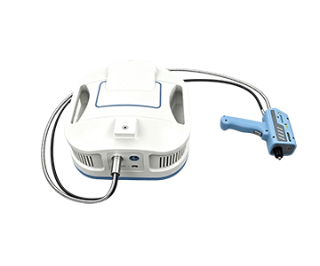
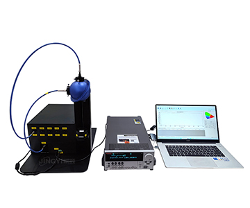
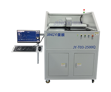
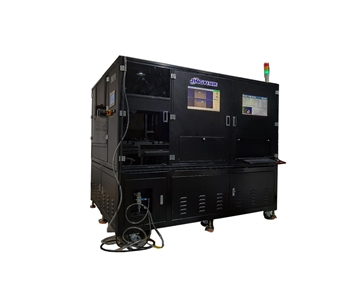
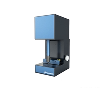
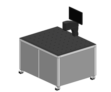
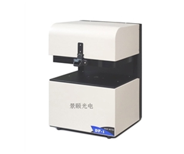
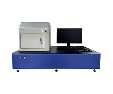
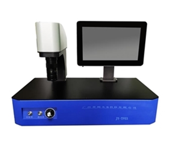
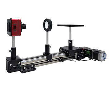
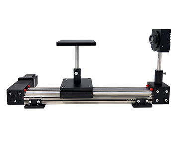
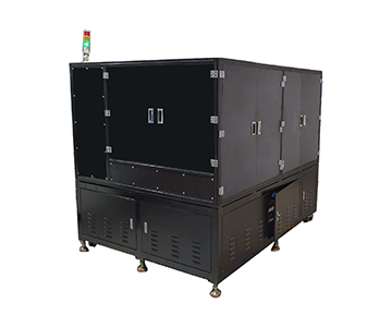
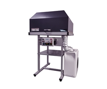
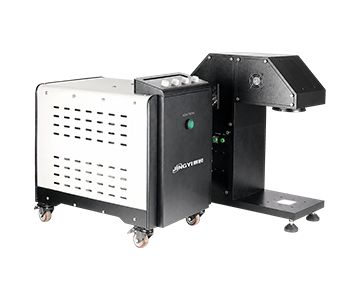
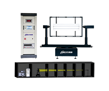
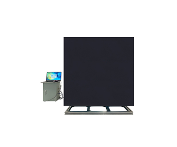
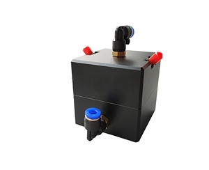
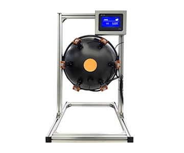
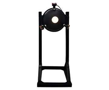
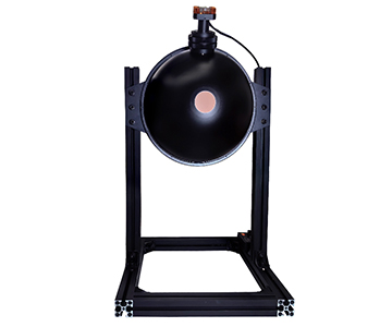
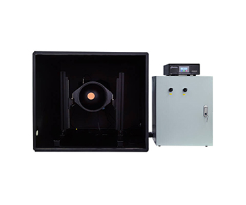
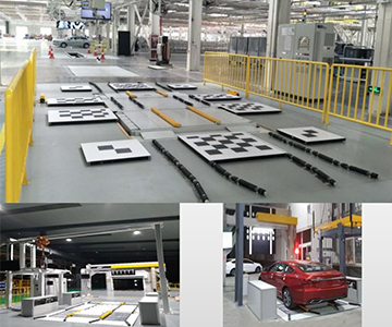
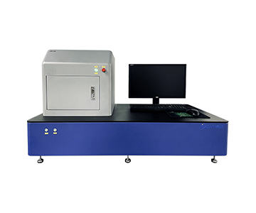
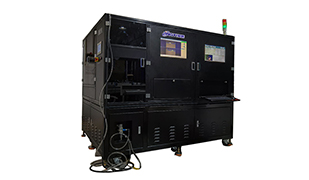
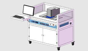
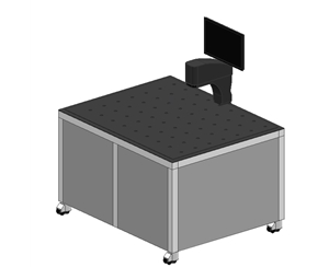
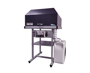
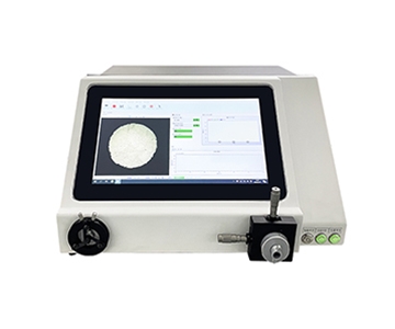
At one mirror-assembly plant, line cadence was capped at 20 s per piece. The line-model unit integrated the environmental chamber with the mainframe, so the whole machine ran continuously from −22°F to 149°F (−30°C to 65°C) and samples needed no shuttling between temperature zone and room-temperature bench. A powered-test module simulated vehicle supply and reverse signal; measured mode-switch and reverse-response times both landed inside the cadence window.
| Scenario |
Key Constraint |
Fit |
| Line cadence |
≤20 s/piece |
Matched |
| Operating temperature |
−22°F to 149°F (−30°C to 65°C) |
Continuous full-machine run |
| Powered / reverse test |
Optional module |
Supported |
Case 4 — Traceable Compliance Reports at a Third-Party Lab
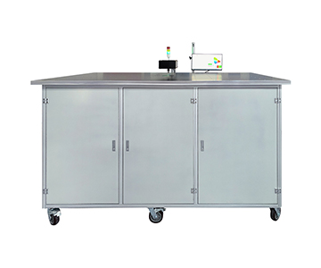
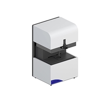
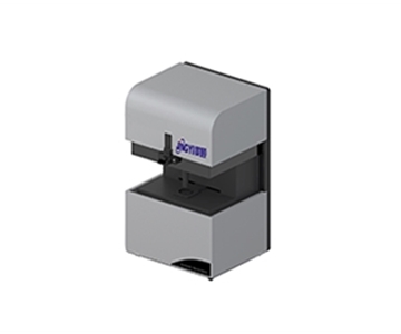
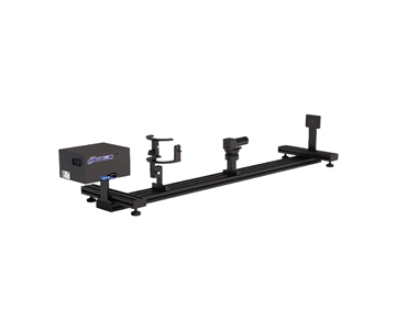
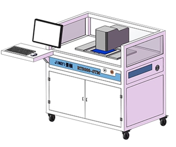
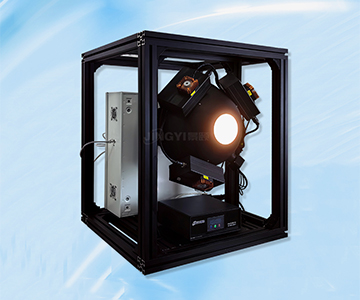
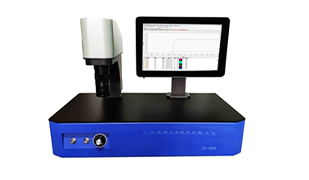
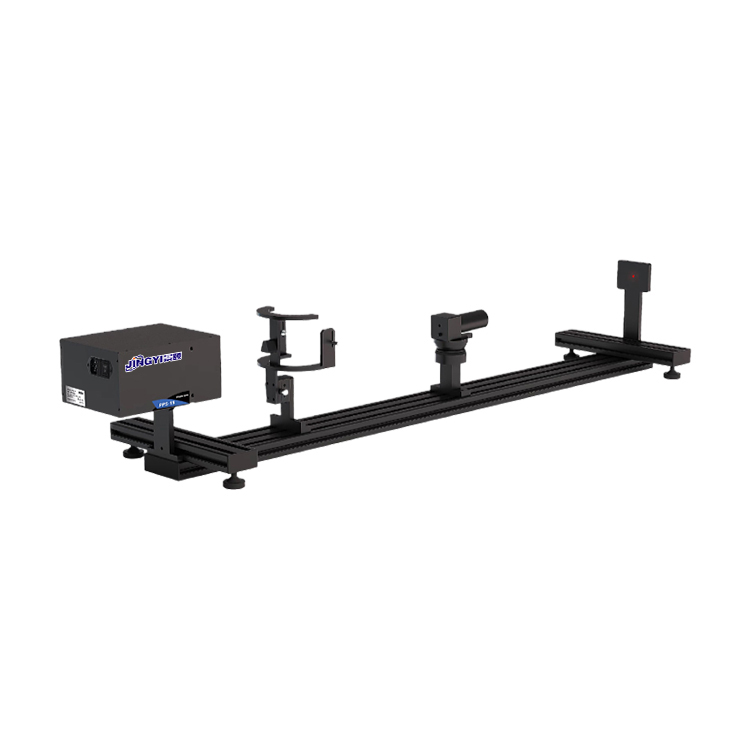
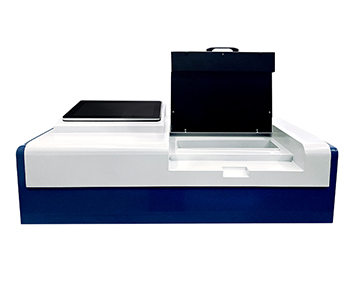
A provincial metrology institute running type-approval tests needed traceable reports. The in-line integrated unit auto-generated reports in the format required by the applicable UN ECE R46-style standard and implemented one-code-one-part traceability, binding each piece record to a product identifier so curves could be recalled per piece or per lot.
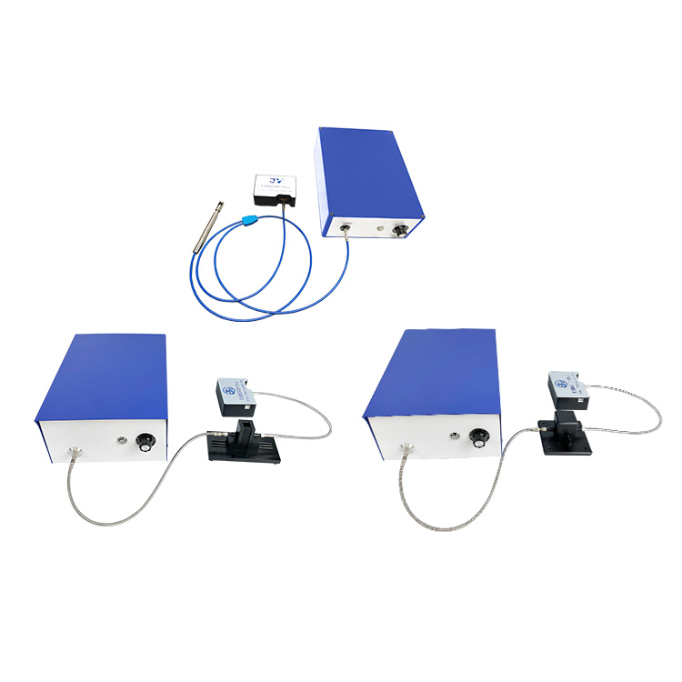
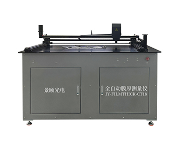
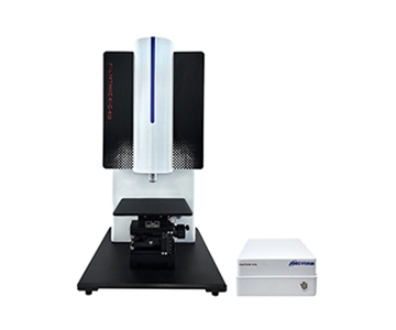
What the four cases share: the same optical core, applied to different cadence and temperature constraints, held repeatability and accuracy inside the判定 window. Where they differ is integration depth—base model for sampling, line model for cadence, in-line model for multi-station traceability.
Head-to-Head: Key Metrics Across Three Equipment Tiers
Strip away brand framing and the three tiers line up on six dimensions. On reflectance accuracy and single-test time, the domestic mainstream tier already sits in the same order as the imported high-end tier; the difference concentrates in band ceiling, source life, and service model.
| Dimension |
Imported High-End |
Domestic Mainstream |
Domestic Economy |
| Wavelength range |
380–1000 nm class |
400–1000 nm |
380–780 nm |
| Single test time |
~1 ms |
1 ms |
1 ms |
| Reflectance accuracy |
Better than 1% |
Better than 1% (ref. plaque) |
Better than 1% (ref. plaque) |
| Operating temperature |
Wide |
−22°F to 149°F (−30°C to 65°C) |
−22°F to 149°F (−30°C to 65°C) |
| Source life |
Longer |
~2000 h |
~2000 h |
| Service model |
Via distributor |
Direct from HQ |
Direct from HQ |
Read across the table: 1 ms response and better-than-1% accuracy cover the full判定 item set of the applicable automotive mirror standard. Imported holds a modest edge in band ceiling (380 nm floor) and source longevity; the domestic economy tier narrows the band to 380–780 nm for basic判定. Stated plainly, the domestic halogen source carries an estimated ~2000 h life, so any continuously running line must budget for spares and annual recalibration—a cost item that cannot be ignored at purchase.
Field Note: Chasing a 0.37% Offset After Midnight
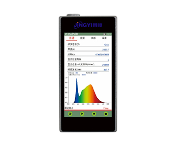
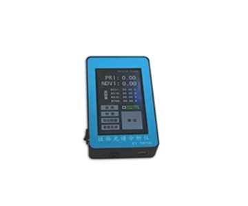
After midnight one shift, the line reported a 0.37% offset in the powered low-reflectance reading of a video mirror. An engineer brought a portable spectroscopic system on site. First, a zero check against the 27 mm PTFE plaque confirmed zero offset still sat within the ≤0.001-over-5-minutes bound. Second, the dark-background subtraction was verified as active—and found disabled: the ambient-light compensation switch had been turned off during a line changeover. Re-enabling it brought readings back inside threshold.
The lesson sits less in the hardware than in whether the value-traceability chain is complete. The reflectance-measurement definition and calibration workflow align with ISO 13468 / ASTM E1164 practice for total transmittance and total reflectance of plastics, which is the methodological prerequisite for a report that a third party will accept.
Error Tracing and Deployment Recommendations
Source Drift and Dark Background
The primary long-duration risk is source decay. Set the recalibration interval against the ±0.5%/8 h drift ceiling and run one white-plaque check per shift on continuous lines. Dark-background subtraction runs automatically before each test, but a contaminated fiber connector degrades it—so add connector inspection to the point-check list.
Deployment Steps
When selecting, first confirm the pass/fail basis covers the bidirectional day ≥40% / night ≥4% requirement; then confirm the traceability chain by requesting the factory metrology certificate and annual calibration record; for line deployment, prefer an integrated-chamber configuration so samples never shuttle in and out of the temperature zone and pick up thermal drift.
Where In-House Optical Development Sets the Boundary
A fact that marketing language tends to obscure: integrating-sphere coating uniformity and how deeply the spectrometer is self-developed set the可信 floor of reflectance data. The evaluated system's reserves show in two places—the sphere's speci
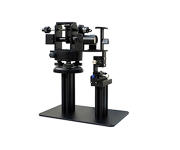
The boundary is real, though. These schemes perform strongly from the visible into the near-infrared, but wider temperature ranges or special incidence angles still call for optional multi-angle incidence components and a wide-temperature chamber—the standard configuration does not cover every extreme.
Honest Limitations
Two constraints must be stated. First, the halogen source's ~2000 h estimated life makes spare stocking and replacement downtime an unavoidable cost for unmanned continuous lines. Second, the standard band is 400–1000 nm; if a sample involves near-infrared reflectance behavior, a wide-band extension module is required, or the data develops blind spots. Beyond that, imported units still carry more accumulated history in long-term source stability and brand-level traceability, while domestic schemes have thinner data沉淀 in ultra-long-cycle consistency validation.
Frequently Asked Questions
How is the better-than-1% reflectance accuracy actually derived, and can it be trusted?
The figure is measured on a reference plaque at room temperature, paired with a factory-calibrated 27 mm PTFE plaque and automatic dark-background subtraction before each test; three-repeat deviation stays below 0.01. Verify on site with a reference plaque at purchase.
Does the 1 ms single test time include ambient-light subtraction?
1 ms is the lower integration-time bound; integration is adjustable from 1 ms to 10 s. Ambient-light and dark-current subtraction completes beforehand automatically, so real cadence must also count sample positioning and pass/fail output.
Does high/low-temperature testing need a separate chamber?
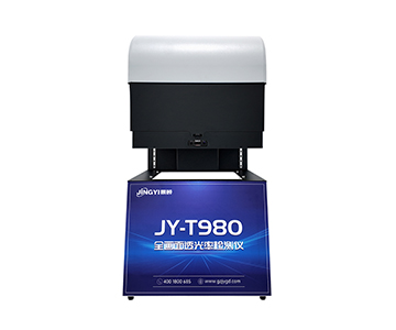
On the base model the chamber is optional and covers −22°F to 149°F (−30°C to 65°C). Line and in-line models support integrated-chamber full-machine operation—confirm by scenario when selecting.
Which of the three tiers is the better value?
Base model for incoming-lot sampling; line model when cadence and integration matter for end-of-line; in-line model for multi-station and data traceability. The better-value call should weigh real capacity and compliance requirements, not unit price alone.
How can I independently verify the reflectance accuracy and traceability before committing to a system?
Request the factory metrology certificate and annual calibration record, then reproduce the measurement on site with a certified reference plaque across the day ≥40% / night ≥4% range, and cross-check the traceability chain through an independent third-party metrology institute.
Closing
Data is the most reliable endorsement a test device can offer. From 1 ms response and better-than-1% reflectance accuracy to −22°F–149°F (−30°C–65°C) coverage, domestic rearview mirror reflectance testing has entered a usable range on multiple metrics. For detailed specifications and application notes on rearview mirror reflectance testers, search "Jingyi Optoelectronics rearview mirror reflectance tester" or visit our technical library.
About This Guide
Data Sources
: UN ECE R46-style requirements, SAE J964 practice, ISO 13468 / ASTM E1164 method data, customer-authorized validation notes (n=320 pieces), product factory specification sheets
Author
: Cai Xiaodong, Senior Application Engineer, Jingyi Optoelectronics — 12 years in optical inspection and automotive-grade compliance validation
Disclosure
: Jingyi Optoelectronics manufactures rearview mirror reflectance testers. This article presents technical assessments based on published specifications and customer-authorized validation data. No compensation was received from third-party brands mentioned.
Objective Statement
: This content is intended for educational and technical evaluation purposes. Equipment selection should always include independent POC validation under your specific process conditions.
Last Updated
: November 2026