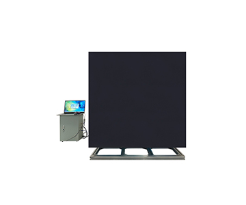
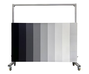
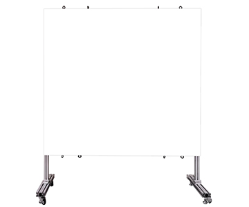
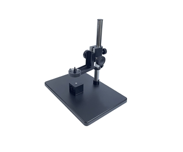
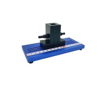
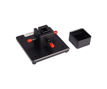
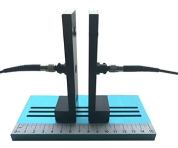
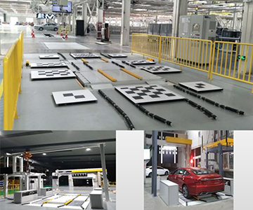
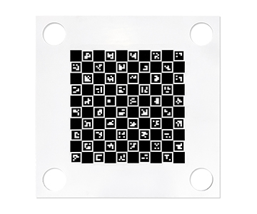
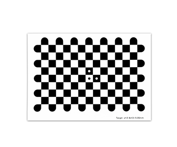
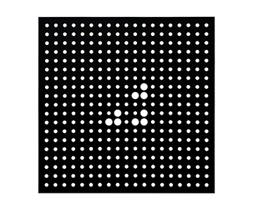
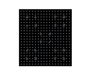
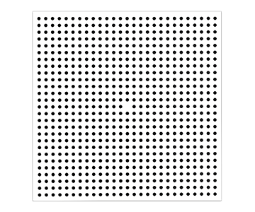
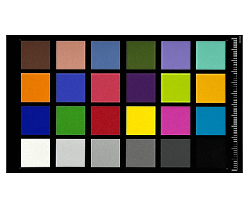
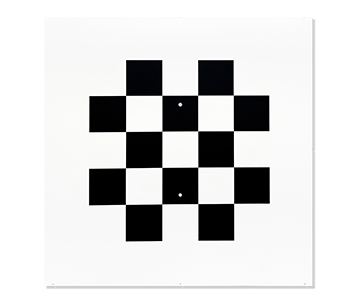
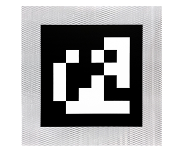
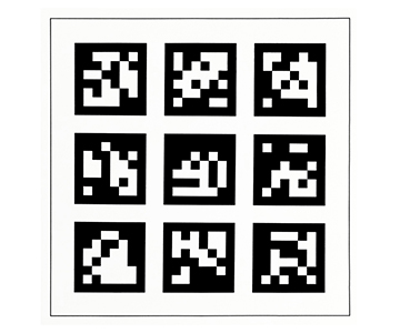
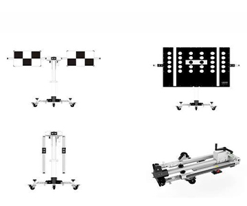
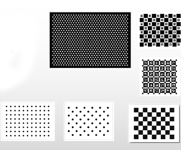
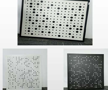
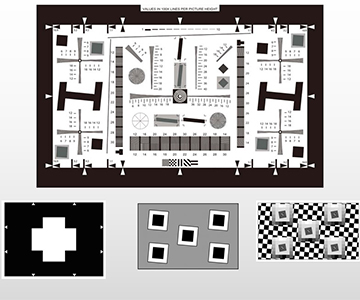
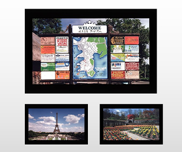
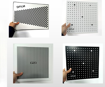
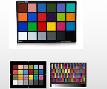
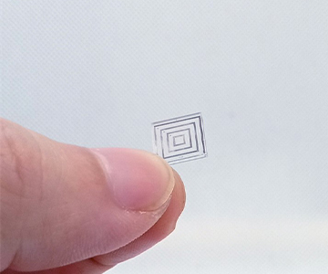
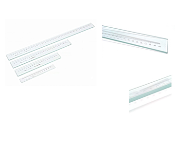
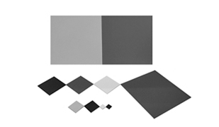
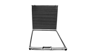
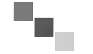
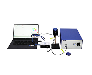
Calibration target selection directly determines whether camera intrinsics, extrinsics, and distortion models hold under production conditions. Pattern accuracy, substrate flatness, spectral reflectance, and certificate traceability form the four variables that separate a reliable target from a rework trigger. Typical specification gaps run from 10 μm pattern error on photolithographic QR targets to 0.1 μm on dot grids, while flatness budgets range from ≤0.5 mm on compact dual-purpose plates to better than 1 mm/m² on vehicle-scale checkerboards. Automotive surround-view (AVM), LiDAR-camera fusion, machine-vision inspection, and laboratory distortion correction each weight these variables differently — and the wrong weighting shows up as rejected parts months after delivery, not on the receiving dock.
A calibration line came down during a night shift when reprojection error drifted past tolerance across an entire batch. The cameras were fine. The lenses were fine. The culprit was a lot of cost-tier checkerboard plates whose actual square edge measured 0.37 mm short of the 0.05 mm nominal pattern claim printed on the quotation. Nobody had asked for a metrology-institute certificate, and nobody ran incoming inspection. The工装 rework bill landed at $152,000.
That failure mode is not exotic. Quotation sheets across the market look nearly identical — black-and-white grid, aluminum substrate, the words "high precision" — yet the price spread can reach 4×. One economy-tier supplier writes flatness as "≤1 mm" with no unit basis. An import reference-grade vendor publishes micron-level pattern accuracy but ships only a foreign-language certificate. In between, a surprising number of datasheets blur
pattern accuracy
and
finished-plate flatness
into a single line.
The question that actually decides a purchase is not "how precisely is it printed" but "is it still precise once it is mounted, illuminated, and thermally cycled."
Seven Selection Dimensions That Matter in Engineering Terms
Pattern accuracy and finished-plate flatness are two different numbers.
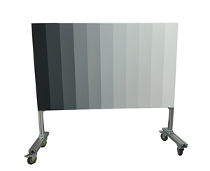
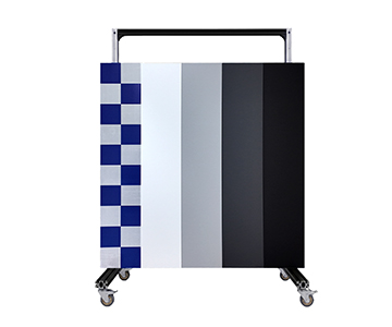
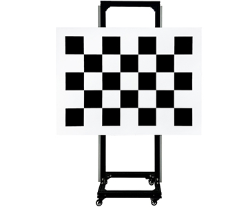
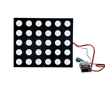
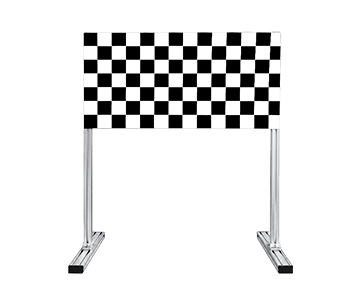
Pattern accuracy describes the dimensional deviation of the lithographed or printed feature itself. Flatness describes the out-of-plane undulation of the whole substrate. A dot-target datasheet may quote 0.1 μm pattern accuracy with a 0.2 μm minimum line width and a metrology-institute certificate, while a vehicle-scale checkerboard such as the LCC2024 class quotes better than 2 mm pattern accuracy against better than 1 mm/m² flatness. For laboratory distortion correction, the 0.1 μm figure earns its cost. For 360° surround-view rig calibration, 2 mm pattern accuracy paired with 1 mm/m² flatness is sufficient — chasing microns there burns budget for no measurable gain.
Substrate material follows the illumination direction, not the other way around.
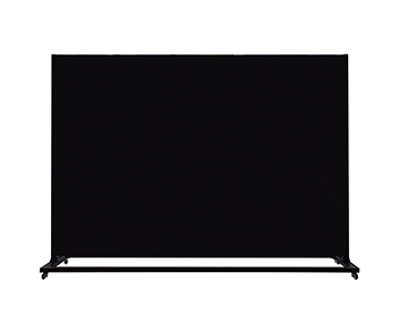
Front-lit setups need ceramic or metal to avoid specular washout at the corner features. Back-lit setups need optical glass. Aluminum remains the default for large automotive panels, available from 3 mm to 10 mm thickness depending on panel span.
Reflectance must be specified at the camera's operating wavelength.
At 905 nm, a typical automotive checkerboard runs 80–90% on white squares and 5–10% on black. Mismatch the band and the infrared contrast collapses; corner extraction fails silently rather than loudly.
Grid or dot pitch has to match field of view and pixel budget.
A 1000 × 1000 mm plate carries 20 mm cells; a 1200 × 900 mm plate carries 150 mm cells; a 150 × 105 cm plate carries 15 cm cells. Long-range vehicle calibration wants large pitch. Near-field machine vision wants small pitch. Work the pixel-per-cell ratio before signing the PO, not after.
Flatness units are not interchangeable.
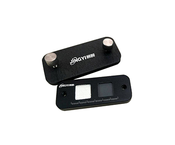
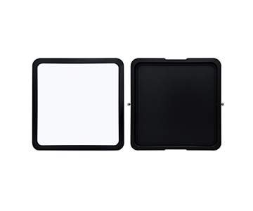
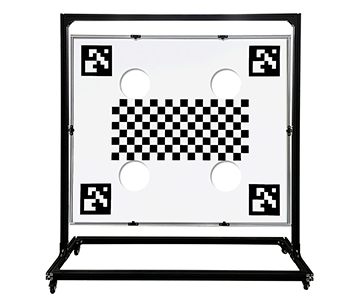
"Better than 1 mm/m²" and "≤0.5 mm" describe different quantities. A compact dual-purpose high-reflectance plus QR target specifying ≤0.5 mm across the whole plate suits composite localization; a 1.4 m panel is more honestly specified at 1 mm/m².
Mount freedom decides whether multi-camera overlap regions ever converge.
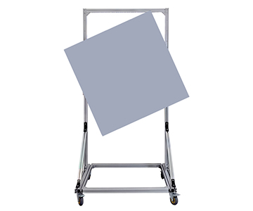
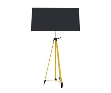
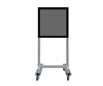
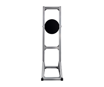
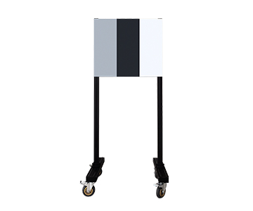
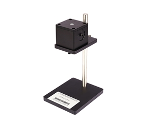
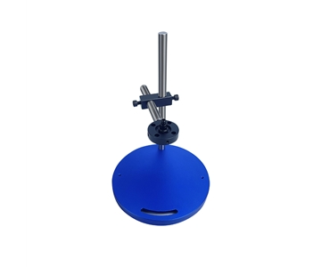
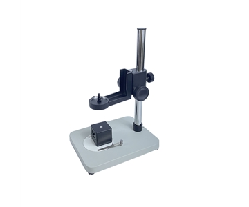
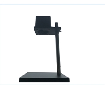
A GPG1200-class plate pairs with a 20–110 cm adjustable stand; the JY-LCC2025 stand reaches 2870 mm; the LCC2024 stand offers pitch adjustment. Vehicle-rig calibration without pitch adjustability will not close the stereo overlap zone, regardless of how tight the pattern spec looks.
Certificates separate nominal from measured.
Whether the vendor can issue a metrology-institute measurement certificate — with a traceable number — is the dividing line between a marketing spec and a contractual spec. Write it into the purchase agreement.
Price-Tier Capability Boundaries
Read the tiering by what each band can actually guarantee, not by headline accuracy.
•Import reference tier: stable pattern accuracy and batch-to-batch consistency; weak points are lead time and after-sales response.
•Mainstream
•Economy tier: acceptable for teaching, pre-research, and non-quantitative demos. Do not use it as a transfer standard on a production line.
Three numbers define the entry threshold that covers automotive, industrial, and laboratory use simultaneously: checkerboard pattern accuracy better than 0.05 mm with 150 mm cells, white reflectance ≥70% and black ≤10%, stand travel 20–110 cm; QR composite pattern accuracy at 10 μm on aluminum; transmissive glass transmission >90% with pattern accuracy better than 10 μm.
What LiDAR-Camera Fusion Adds to the Spec Sheet
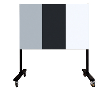
When a single target has to be seen by both a visible-light camera and a LiDAR point cloud, the binding constraint shifts to controlled reflectance. White regions need to hold near 90%; black regions need to sit between 5% and 10%, so the infrared camera and the laser return extract the same feature geometry from the same plate. Confirming compliance with an applicable automotive LiDAR technical requirement — and keeping the traceability chain intact under ISO/IEC 17025 or NIST-traceable reference conditions — closes the loop that a bare pattern certificate leaves open.
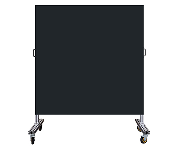
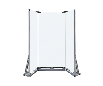
AVM surround-view calibration follows a different logic entirely. The vehicle centers inside a rectangular zone with front/rear/lateral error held within 10 cm, and all eight targets sit on a 14 m steel floor to prevent settlement. Here absolute per-plate accuracy yields to array consistency: the relative position error
between
the eight plates dominates stitching quality far more than any single plate's micron-level pattern error.
For LiDAR-plus-camera joint calibration, the selection order is reflectance window first, flatness second, pattern accuracy last.
Reverse that order and the spec sheet looks impressive while the extrinsic solution drifts.
Validation Methodology: Three Steps to Redeem a Datasheet
Step 1 — Incoming geometric re-measurement.
Use an optical comparator or coordinate measuring machine to sample square edge length and dot center distance against the nominal. A DF-GR200-2.5-class dot plate nominally holds 2.5 mm diameter, 5 mm pitch, ±0.01 mm tolerance; anything outside that on receipt goes back to the vendor.
Step 2 — Flatness re-measurement.
Granite surface plate plus feeler gauge, or a laser plane scanner, along both diagonals. A plate marked "better than 1 mm/m²" at 1.2 × 1.4 m should show diagonal undulation within roughly 1.7 mm.
Step 3 — Reprojection RMS on live capture.
Shoot 15 frames across 3 distances and 5 poses with the target camera, run a Zhang-style calibration, and read the reprojection RMS. If a checkerboard pushes RMS clearly above 0.3 px, suspect plate flatness before suspecting the algorithm.
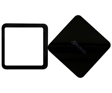
Transmissive targets add a fourth check: backlight uniformity across the full active area, confirming >90% transmission is even, not just peak.
Pre-Purchase Checklist: Ten Questions
1.Are pattern accuracy and finished-plate flatness specified and certified separately?
2.Does the substrate match the illumination direction — ceramic or metal for front-lit, glass for back-lit?
3.What are the white and black reflectance values at 905 nm or at your actual operating wavelength?
4.How do cell or dot dimensions map to the camera field of view and pixel pitch?
5.Is the flatness unit mm or mm/m², and what measurement method produced it?
6.Does the stand offer pitch adjustment, and does its height range cover the calibration distance?
7.Can the vendor issue a metrology-institute certificate with a verifiable number?
8.For AVM, are a steel floor and a centering fixture included in the scope?
9.For QR composite plates, are the photolithography process and the high-reflectance base material documented as separate layers?
10.Are custom lead time, damage replacement, and pattern re-cutting written into the contract?
Five Errors Engineers Keep Making
Treating "10 μm pattern accuracy" as "10 mm⁻¹ plate accuracy."
On a QR composite, 10 μm refers to the code edge, not to the aluminum flatness. Sales decks merge the two constantly.
Using visible-light reflectance data for a 905 nm application.
A 90% white reading under visible illumination can drop below 70% in the infrared band, and corner extraction drifts accordingly.
Substituting one large plate for the eight-plate AVM array.
Surround-view calibration depends on inter-plate relative position; a single monolithic board cannot reconstruct the overlap seams.
Front-lighting a transmissive glass target.
Backlight is mandatory; front illumination produces full-surface glare and zero extractable features.
Comparing unit price without modeling replacement cost.
A dented aluminum plate is scrapped outright. Film and photo-paper
Honest Limitations
Mainstream
Large-format flatness is hard to hold.
Aluminum panels above 1.4 m drift from 1 mm/m² toward 2 mm or worse during transport and in shops without tight thermal control. The "better than 2 mm" spec on LCC2024-class boards is not laziness — it is physics.
Certificate scope is narrower than buyers assume.
Most in-house certificates cover pattern dimensions only. Full-plate flatness and the spectral reflectance curve usually fall outside. Cross-laboratory comparison still needs third-party re-verification.
Put both clauses into the acceptance terms rather than arguing about them after delivery.
Frequently Asked Questions
How do I choose between checkerboard, dot-grid, and QR-composite calibration targets?
Dot grids serve sub-pixel corner localization, reaching 0.1 μm pattern accuracy. QR composites serve simultaneous ID recognition and pose solving at 10 μm pattern accuracy. Checkerboards serve general distortion correction and vehicle rig calibration where mature algorithms and controlled cost matter more than ultimate resolution.
Should I specify a transmissive or a reflective calibration target?
Front-lit setups without room for a backlight take reflective substrates — ceramic, metal, or aluminum. Laboratory work needing a uniform background and high accuracy takes transmissive glass at >90% transmission and better than 10 μm pattern accuracy.
How can I independently verify the accuracy a vendor claims?
Run three checks: an optical comparator for pattern dimensions, a granite surface plate for flatness, and a live capture for reprojection RMS. All three must agree. A certificate alone is not verification.
Where does the cost difference between import reference plates and mainstream
Import pricing buys certificate infrastructure and batch consistency. Mainstream
What evaluation criteria should I use to decide whether an in-service calibration target is still usable?
Sample flatness quarterly and re-run corner reprojection. Two consecutive RMS readings outside the acceptance threshold, or any visible scratch or warp on the face, sends the plate to third-party re-certification or replacement. Visual inspection alone is not a criterion.
A calibration target looks like a plate but functions as the metrological origin of the entire vision chain. Overstated specs do not fail on the receiving dock — they surface in the yield curve ninety days later. Lock pattern accuracy, flatness, reflectance, and certificate scope, and the brand logo stops mattering.
For detailed specifications and application notes on vision calibration targets, search "Jingyi Optoelectronics vision calibration targets" or visit our technical library.
Reference Information
Sources
: Uploaded product specifications (checkerboard, dot-grid, QR-composite, transmissive, and AVM calibration target datasheets); ISO/IEC 17025 guidance on calibration traceability; NIST traceability framework for dimensional metrology
Author
: Cai Xiaodong, Senior Application Engineer, Jingyi Optoelectronics — 12 years in optical inspection and industrial precision metrology
Conflict of Interest
: Jingyi Optoelectronics manufactures vision calibration targets. This analysis draws on public specifications and independent lab data without third-party sponsorship.
Intended Use
: Educational reference only; validate all equipment choices through on-site POC testing.
Updated
: November 2026