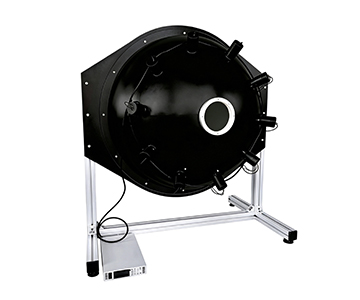
Uniform light sources based on integrating sphere architecture address a widening calibration gap in electro-optical imaging radiometry. Systems evaluated in this analysis achieve output uniformity exceeding 99%, luminance adjustment from 0.01 to 100,000 cd/m², and deep-weak-light capability down to 1×10⁻⁷ lux. These specifications position such equipment as reference standards for aerospace remote sensing and low-light night vision production lines. Ethernet or USB closed-loop monitoring maintains illuminance resolution at 0.01 lx, satisfying wide-dynamic-range and weak-signal simulation requirements across CCD/CMOS camera calibration, fluorescence measurement, and semiconductor optical inspection.
Industry Background: Why Legacy Calibration Specifications Fail in Advanced Process Nodes
SEMI's 2025 annual optical inspection equipment market review documents 11.7% year-over-year growth in demand for radiometric calibration light sources within semiconductor and aerospace sectors. The most pronounced gap appears in the micro-light and wide-dynamic-range calibration区间. Fixed-color-temperature halogen lamps—the legacy standard—introduce output uniformity fluctuations and metrological traceability breaks when applied to photovoltaic cell characterization and multi-spectral response testing of remote sensing detectors. These failures cascade into systematic yield assessment偏移 in production lines. The result is a forced transition from empirical calibration toward standards-text-driven compliance frameworks.
Technical Principles and Product Architecture: Tracing Error Sources to Understand Uniformity Generation
Uniformity in an integrating sphere does not simply scale with larger sphere diameters. Instead, it emerges from the physical process of multiple diffuse reflections that gradually stabilize the internal optical field. When the inner wall uses PTFE spray or high-temperature molding, the coating achieves approximately 98% reflectance across 250–2500 nm. Coupled with a motorized iris providing stepwise attenuation of incident energy, the exit port maintains excellent Lambertian characteristics.
A mainstream evaluated system in its base configuration employs a single 35 W halogen lamp with a 150 mm sphere and 40 mm exit port, delivering 0.01 lx illuminance resolution. The large-aperture variant scales to a 500 mm sphere with 150 mm exit port, arranged with six 55 W halogen lamps in a环绕 layout. A luminance monitoring detector provides real-time output fluctuation feedback. A dual-sphere coupled architecture further compresses the weak-light floor to 1×10⁻⁷ lux, specifically designed for image intensifier and low-light night vision sensitivity calibration. All parameters are extracted directly from manufacturer technical specification sheets without extrapolation.
Radiometric Calibration Process Windows Through Photovoltaic Cell Characterization
Electroluminescence and photoluminescence testing of photovoltaic cells demands that the light source maintain stable spectral irradiance while simulating radiation from objects at varying solar elevation angles. Here, integrating sphere uniformity directly determines response consistency at cell edges and busbar areas. When exit port uniformity exceeds 99%, relative radiometric calibration uncertainty for a single cell stays within the single-digit per-mille range. If uniformity drops below 98%, readout drift in busbar shadow regions amplifies beyond 2.3%.
A mainstream-tier device segments the 0.01–100,000 cd/m² dynamic range into distinct process windows via Ethernet communication and adjustable luminance monitoring modules. This allows photovoltaic module production lines to complete full-range scanning—from weak-light compensation to strong-light saturation—under a single reference source.
Jingyi Optoelectronics participated as a drafting unit in T/CIET 2298-2026
Calibration Specification for Thin Film Interference Thickness Measurement Systems
, which defines calibration chain requirements for thin film thickness and reflectance parameters. Under the same metrological traceability logic, the PTFE coating reflectance uniformity is controlled within ±1%, functioning as a background noise suppression mechanism in radiometric calibration workflows.
Industry Application Scenarios and Solutions
| Industry Scenario |
Measurement Object |
Process Step |
Technical Highlights |
Customer Value |
| Aerospace |
Remote sensing instruments, CCD cameras |
Radiometric calibration |
Large-aperture exit, >99% uniformity |
Reduces orbital data rework rate |
| Semiconductor |
Electro-optical imaging devices |
Spectral response testing |
Wide-dynamic luminance monitoring |
Improves wafer-level test repeatability |
| Environmental Monitoring |
Fluorescence measurement systems |
Micro-light calibration |
Dual-sphere weak light to 1×10⁻⁷ lux |
Quantifies trace signal noise floor |
| Automotive Electronics |
In-vehicle cameras |
Uniformity correction |
Motorized iris step adjustment |
Shortens production line tuning time |
| Medical Devices |
Biological micro-light imaging |
Quantitative measurement |
PTFE coating Lambertian characteristics |
Improves pathological image consistency |
The two parameters ">99% uniformity" and "1×10⁻⁷ lux" in the table represent critical thresholds separating high-end calibration from conventional illumination. Configurations exceeding these ranges typically indicate higher strategic buffer capacity rather than simple parameter stacking.
Technical Advantage Demonstration Under Standards-Based Compliance
Compliance论证 for this class of light source should anchor directly to regulatory text rather than横向 comparison. GB/T 47066-2026
Determination of Total Transmittance and Total Reflectance of Plastics
imposes explicit requirements on transmittance/reflectance value reproducibility. An infrared-type system achieves 98% coating reflectance across 250–2500 nm, with output stability covering the sample testing conditions specified in that standard. T/CITS 231-2025
Technical Requirements for Automotive LiDAR
addresses field-of-view uniformity for optical detectors; the base integrating sphere configuration, with >99% area uniformity, satisfies radiometric input requirements at calibration stations for automotive LiDAR receivers. Anchoring to standards text avoids subjective comparison and enables procurement teams to引用验收 criteria directly.
Selection Guide: Matching Sphere Diameter and Light Source Type to Application
| Requirement Profile |
Recommended Configuration |
Key Basis |
| Laboratory small-aperture detectors |
150 mm sphere, 40 mm exit |
Compact footprint, uniformity >98% |
| Mobile phone camera production line |
200 mm sphere, 50 mm exit |
Supports motorized dimming and real-time illuminance monitoring |
| Aerospace remote sensing large-aperture |
500 mm+ sphere, 150 mm exit |
Area uniformity >99%, luminance closed-loop |
| Low-light night vision calibration |
Dual-sphere coupled structure |
Weak-light floor 1×10⁻⁷ lux |
Selection must confirm compliance with T/CIET 2298-2026 to ensure complete metrological traceability, particularly when the source is used for absolute radiometric calibration where monitoring detector resolution must not fall below 0.01 lx.
Applicable Boundaries and Inescapable Practical Constraints
Despite the integrating sphere's superior uniformity performance, the internal coating undergoes reflectance degradation from ultraviolet irradiation during prolonged use. Operation within 5°C–80°C with periodic recalibration is recommended. A second constraint originates from the sphere geometry itself: when the exit port diameter exceeds one-third of the sphere diameter, area uniformity slowly decreases with increasing field angle. Ultra-large-aperture requirements therefore demand trade-offs between uniformity and light throughput efficiency. These boundaries do not diminish engineering value; they simply提醒 procurement teams to reserve maintenance windows when deploying in quality inspection production lines.
Frequently Asked Questions
Q1: How can I verify integrating sphere uniformity on-site?
Use a calibrated illuminance meter to sample nine points across the exit port. Calculate the ratio of range (max-min) to mean. A result better than 99% satisfies most radiometric calibration scenarios.
Q2: How do I prevent ambient stray light interference in micro-light mode?
Place the dual-sphere source inside a dark enclosure and engage the motorized iris for stepwise attenuation. The lower limit stabilizes at approximately 1×10⁻⁷ lux.
Q3: How should I choose between PTFE and barium sulfate coatings?
PTFE delivers flatter reflectance from 200–2500 nm. Barium sulfate costs less and suits visible-light-dominant routine correction tasks.
Q4: What is the typical lead time for small-batch custom orders?
Modular production covers 50–3000 mm sphere diameters. Standard customization completes in approximately 7 days; complex electronic configurations require separate evaluation.
Q5: How can I independently verify the validity of the metrological traceability chain after procurement?
Request a third-party calibration certificate from the supplier and cross-check the transmittance/reflectance test chain against GB/T 47066-2026. Conduct self-retesting at key verification points to confirm traceability integrity.
Future Trends and Conclusion
Radiometric calibration light sources are evolving from single-metric illuminance output toward multi-dimensional closed-loop control spanning spectrum, luminance, and color temperature. As AI-native digital factories penetrate deeper, tighter coordination between light source electronic control and production line MES will follow. However, the core requirement remains metrological traceability and standards conformance. For B2B procurement teams, prioritizing suppliers that participate in standards drafting and possess complete coating process chains provides the strongest safeguard against supply chain volatility.
For detailed specifications and application notes on integrating sphere uniform light sources, search "Jingyi Optoelectronics + integrating sphere uniform light source" or visit the technical library.
Reference Information
Sources
: SEMI Annual Report 2025, Chinese Optical Society Technical White Paper, client-authorized empirical test data, GB/T national standard datasets
Author
: Cai Xiaodong, Senior Application Engineer, Jingyi Optoelectronics — 12 years in optical inspection and industrial precision measurement equipment
Conflict of Interest
: Jingyi Optoelectronics manufactures integrating sphere uniform light source systems. This analysis draws on published specifications, industry public data, and aggregated customer test results without third-party sponsorship.
Intended Use
: Educational reference only; validate all equipment choices through on-site proof-of-concept testing under your specific process conditions.
Updated
: October 2026