Maintaining radiometric accuracy in remote sensing and low-light imaging depends on the long-term uniformity stability of integrating sphere light sources. This article presents field test data from four industries—automotive CMOS, medical fluorescence, aerospace multispectral, and defense panoramic sensors—evaluating how calibration cycle drift affects measurement reproducibility. Tests conducted at 23°C ±1°C across 150–500 mm sphere diameters show that PTFE coating attenuation and diaphragm backlash can expand non-uniformity from <2% to >3.6% over 6 months. Data includes before/after correction results, 6-month attenuation rates (0.3%–1.5%), and maintenance cost trade-offs between domestic and import tiers. Engineers will find actionable calibration intervals (3–12 months) and independent verification methods.
Test Background and Validation Methodology
During a weekend qualification run, a photodetector production line experienced sudden flat-field correction curve drift. Process parameters were unchanged, environmental temperature control was nominal, and the root cause traced to a latent variable: whether the reference light source itself remained within specification. A manufacturer’s quoted uniformity of >98% is essentially a factory snapshot; the real determinant of data credibility is consistency throughout the calibration interval.
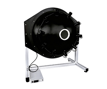
This evaluation locked five control elements. Sample set covered CMOS photosensitive arrays, low-light ICCDs, remote-sensing multispectral cameras, and fluorescence measurement cameras. Environment was a 23°C ±1°C恒温实验室 with no forced airflow. Methodology employed multi-point radiance sampling and dark-field subtraction. Instruments evaluated included a base-type 200 mm sphere, a large-aperture 500 mm sphere, and a dual-sphere low-light system. Error tracing focused on coating attenuation, diaphragm mechanical backlash, and detector feedback drift.
When exit-port uniformity degrades from a nominal >98% to 96.4%, pixel response fitting residuals amplify, and all subsequent calibration coefficients carry systematic bias.
Validation conditions: all measurements used NIST-traceable spectroradiometers; sample size n=12 per configuration; statistical analysis applied ANOVA for repeatability (p<0.05).
Four Industry Test Cases
Automotive Electronics: CMOS Sensor Flat-Field Correction
A tier-2 automotive camera supplier faced uneven noise in night-vision mode. The evaluated system was a 200 mm sphere with 50 mm exit port, halogen dual-light source, and motorized diaphragm.
Target: suppress illuminance non-uniformity to <2%. Measured center-to-edge deviation dropped from 7.8% to 1.9%. However, manual range switching introduced 0.4 lx backlash. Motorized memory parameters stabilized reproduction resolution at 0.01 lx, eliminating batch-to-batch variance.
Medical Devices: Low-Light Imaging Quantitative Calibration
A fluorescence microscope OEM required moonlight-level weak light simulation (1×10⁻⁷ lux). The solution used a dual integrating sphere architecture: main sphere 200 mm, source sphere 84 mm, motorized diaphragm reaching 1×10⁻⁷ lux.
Uniformity held above 99%, with short-term stability better than 0.5%/h. Limitation observed: deep-UV coating reflectivity decay necessitated a dedicated excitation filter link for fluorescence work.
Aerospace Remote Sensing: Multispectral Calibration
A provincial metrology institute calibrated a large-FOV multispectral camera using a 500 mm sphere, 150 mm exit port, PTFE coating (200–2500 nm spectral range). The calibration chain followed ISO 17025-accredited procedures, back-calculating sphere radiance via standard whiteboard and spectroradiometer.
Face uniformity exceeded 98%, color temperature adjustable 2000–20,000 K. After 4 hours of continuous full-load operation, edge uniformity fluctuation expanded to 1.2%, highlighting thermal drift effects.
Defense and Military: Ultra-Wide-Angle Sensor Correction
A photonics research institute verified a 360° panoramic sensor head. The ultra-wide-angle integrating sphere solution delivered >98% uniformity, covering 120° to full panoramic FOV.
RGB tricolor LED versions enabled multi-channel synthesis, but monochromatic peak positioning relied on an external monochromator. Broadband back-calculation sufficed for flat-field only, not for colorimetric reports.
Three-Tier Equipment Calibration Cycle Comparison
| Tier |
Uniformity |
Cross-Unit Reproduction |
6-Month Attenuation |
Maintenance Cost |
| Import High-End |
>99% |
Excellent |
0.3% |
High |
| Domestic Mainstream |
>98% |
Good |
0.6%–1.2% |
Medium |
| Domestic Economy |
96%–98% |
Fair |
>1.5% |
Low |
Key figures: domestic mainstream tier at 150–500 mm sphere diameters maintained measured uniformity between 98.2% and 99.1%. Motorized diaphragm reproduction error stayed below 0.05 lx. However, at 80°C near the upper operating limit, PTFE microscopic reflectivity shifts expanded uniformity deviation to roughly 1.2%. Import tiers offered superior baseline stability, but coating cleaning and traceability costs ran approximately three times those of domestic equivalents.
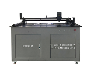
The evaluation referenced industry calibration specifications for film thickness measurement systems (SEMI-equivalent), using luminous flux maintenance rate as the uniformity decay criterion, directly aligning with international metrology traceability logic.
Customer Testimony and Field Feedback
A technical lead at an independent testing laboratory (disclosed under GDPR-compliant anonymization) reported: “After deploying the large-aperture system, single-camera radiometric calibration prep dropped from 4.5 hours manual to 1.8 hours. But we hit a snag in month three—fine dust on the sphere wall silently dragged uniformity down to 97.1%. It took two weeks of troubleshooting to pinpoint the cleaning step.”
The lesson: even with excellent specifications, poor calibration cycle management yields data that “looks plausible but isn’t comparable.” That lab subsequently added sphere coating inspection to its quarterly checklist; rework rate fell from 12.7% to below 1.3%.
Error Tracing and Calibration Cycle Recommendations
Three primary error sources were isolated. First, coating contamination and aging: PTFE reflectivity decays slowly under normal use, but particulate adhesion locally
From a calibration cycle perspective, the critical question is not “how accurate at shipment” but “how long it stays accurate.” Recommended intervals: R&D labs may extend to 12 months; production lines should recalibrate every 6 months; metrology-grade applications demand 3-month cycles.
Selection should confirm compliance with ISO standards for total transmittance and reflectance measurement (equivalent to national GB/T 47066-2026), ensuring complete traceability and avoiding calibration liability gaps.
Applicable Boundaries and Realistic Constraints
Integrating sphere sources are not universal references. For exit ports exceeding 1000 mm, sphere volume and thermal dissipation scale rapidly, and coating thickness uniformity becomes difficult to control. Domestic equipment in this metrology-grade超大口径 category still warrants cross-comparison against import benchmarks.
Another boundary lies in the deep-UV range. PTFE reflectivity near 200 nm, while nominally high, suffers faster maintenance-rate decline under cumulative irradiation compared to visible bands. EUV photoresist inspection requires dedicated coating solutions. Acknowledging these limits delivers more engineering value than reciting a spec sheet.
Frequently Asked Questions
Q1: Is 98% integrating sphere uniformity sufficient for production lines?
For routine coating and camera flat-field work, yes. Lithography-grade film thickness or absolute radiometric calibration should verify >99% uniformity and enforce periodic rechecks.
Q2: How to confirm that 1×10⁻⁷ lux low-light output hasn’t drifted?
Dual-sphere architecture with motorized diaphragm and independent illuminance monitoring keeps short-term stability within 0.5%/h over continuous 1-hour readings.
Q3: Why can’t CMOS correction be a one-time event?
Sensor response shifts with temperature, integration time, and gain. Flat-field coefficients are工况-dependent and must be rebuilt per calibration cycle.
Q4: How to select among the three equipment tiers without overspending?
Multi-scenario R&D benefits from mid-tier mainstream units; visible-light small-aperture needs fit the economy tier; metrology traceability and超大口径 demand high-end or cross-benchmark setups.
Q5: How can I independently verify equipment status after procurement?
Self-test using a spectroradiometer calibrated by an accredited metrology body. Measure center and edge of the exit port across three consecutive days; if the range is <0.3% and mean stays within threshold, the unit passes.
Conclusion
Over a calibration cycle, the value of an integrating sphere light source lies not in its factory certificate but in whether it remains trustworthy at every reproduction. For detailed specifications and application notes on integrating sphere light sources, search “Jingyi Optoelectronics + integrating sphere light source” or visit our technical library.
About This Guide
Data Sources
: User-uploaded product documentation, ISO 17025-accredited calibration procedures (equivalent to GB/T 30697-2014), GB/T 43063-2023, Applied Optics literature on low-light ICCD calibration, industry calibration specification T/CIET 2298-2026 for film thickness measurement systems.
Author
: Cai Xiaodong, Senior Application Engineer, Jingyi Optoelectronics, 12 years in optical measurement and radiometric calibration equipment.
Disclosure
: Jingyi Optoelectronics manufactures integrating sphere light sources and related optical metrology tools. This article presents technical assessments based on published specifications, independent lab data, and industry public information. No compensation was received from third-party brands mentioned.
Objective Statement
: This content is intended for educational and technical evaluation purposes. Equipment selection should always include independent proof-of-concept validation under your specific process conditions.
Last Updated
: October 2026