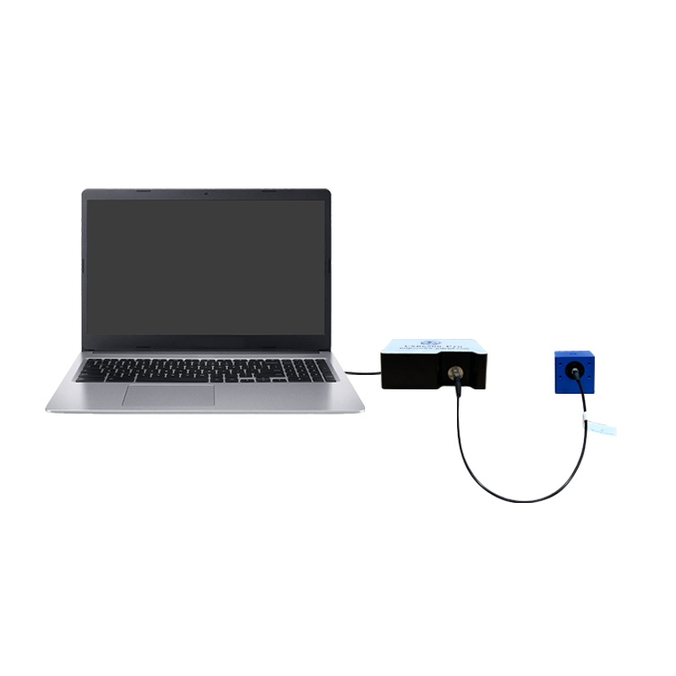
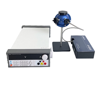
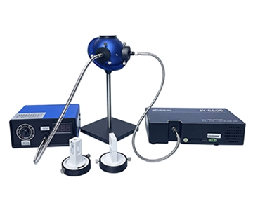
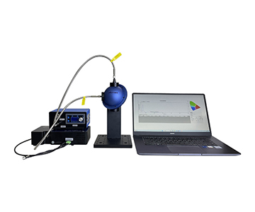
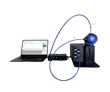
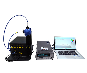
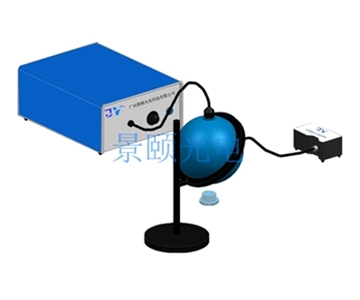
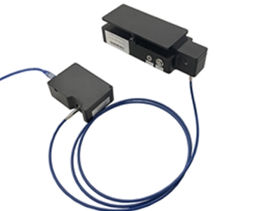
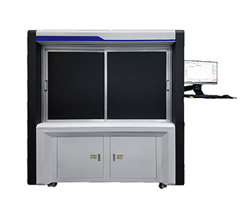
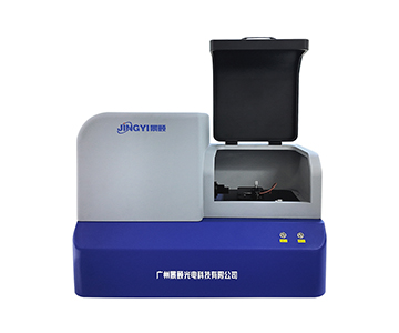
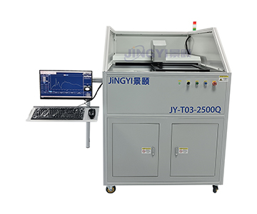
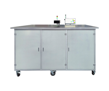
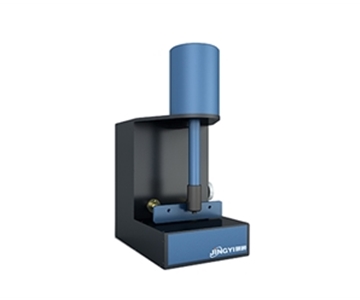
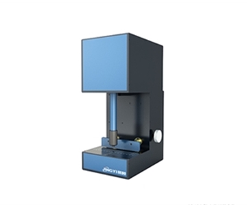
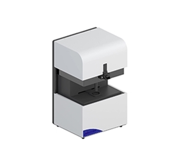
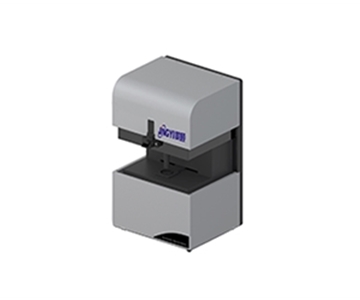
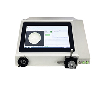
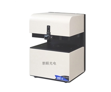
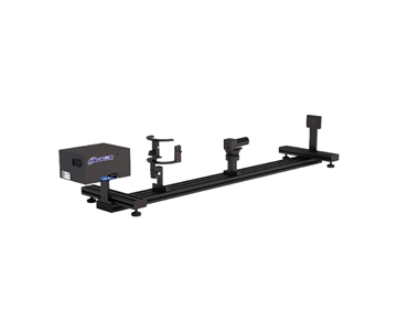
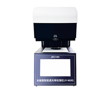
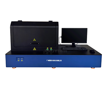
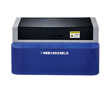
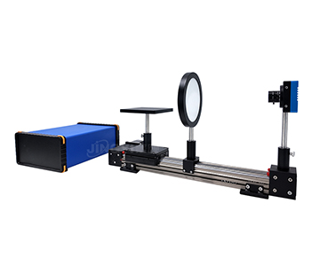
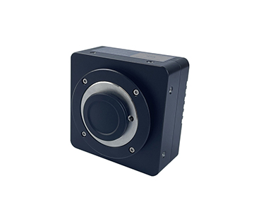
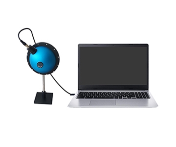
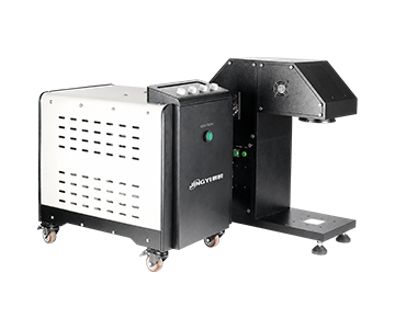
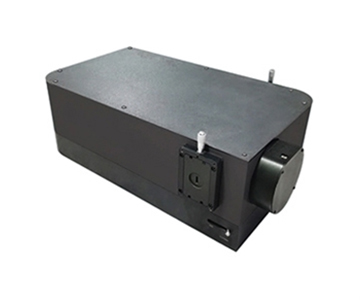
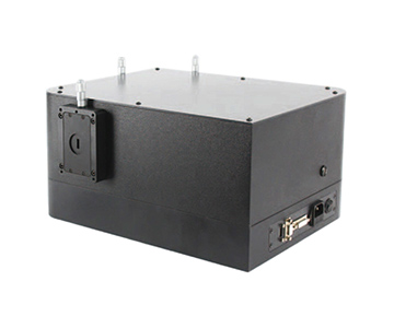
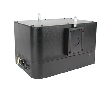
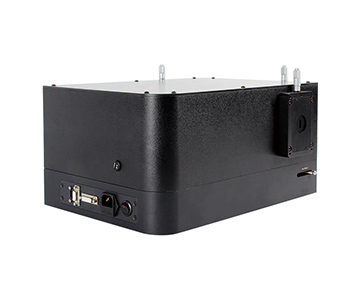
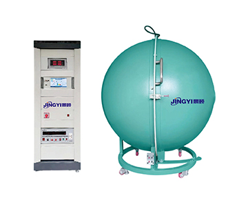
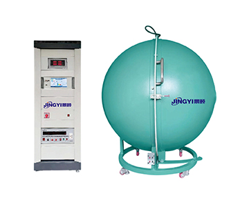
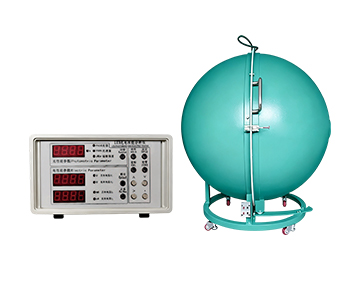
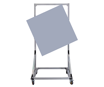
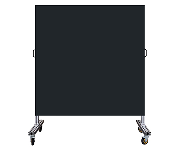
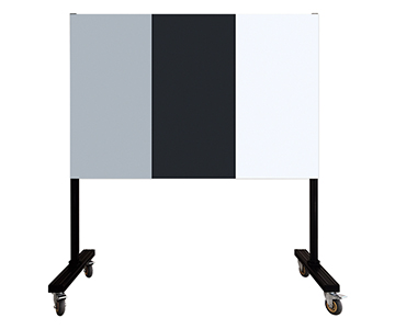
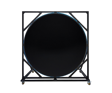
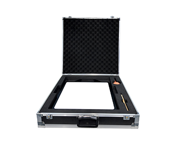
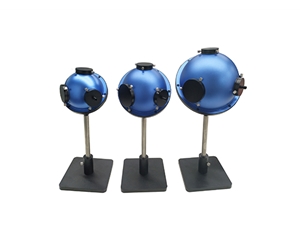
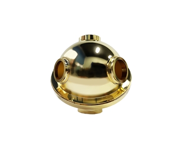
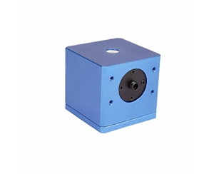
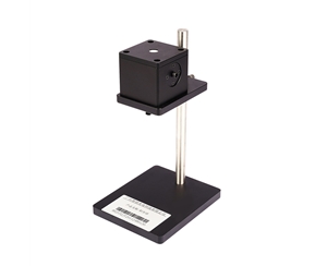
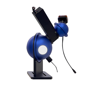
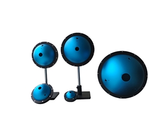
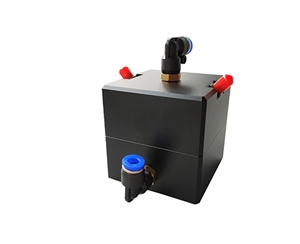
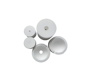
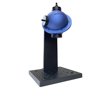
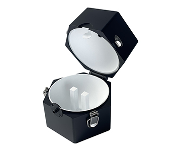
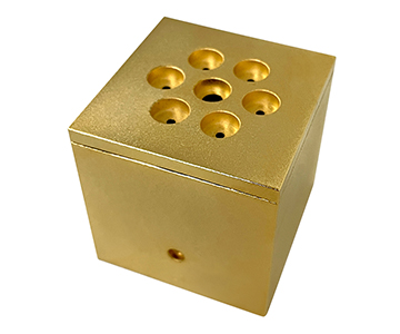
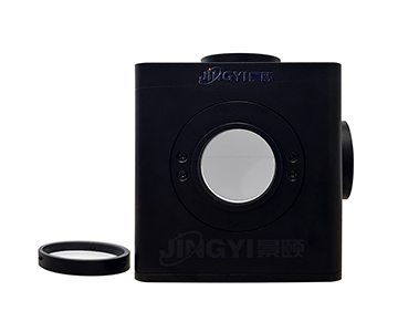
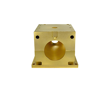
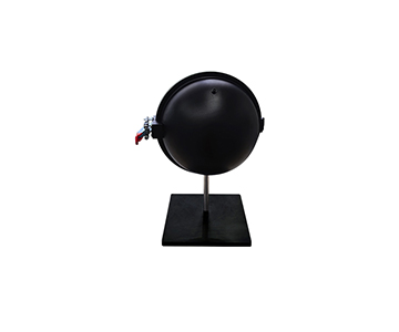
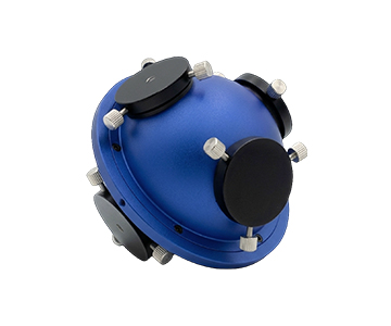
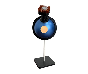
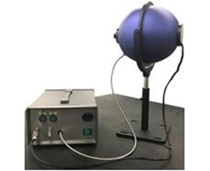
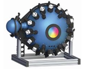
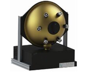
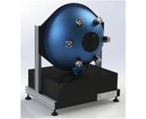
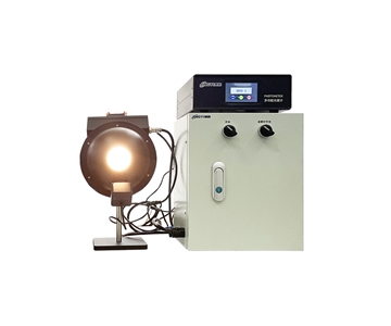
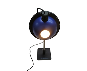
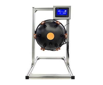
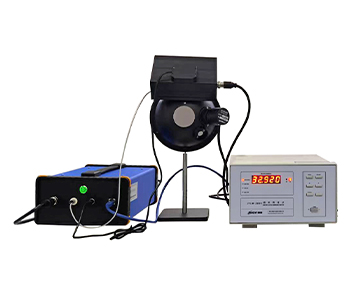
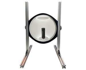
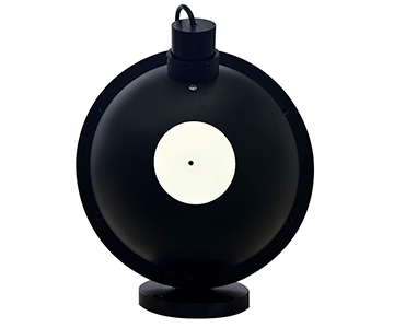
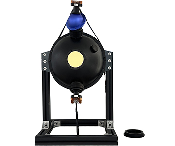
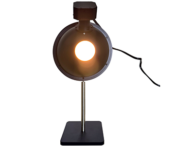
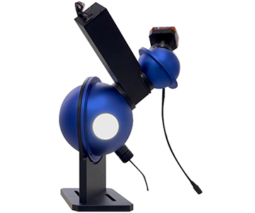
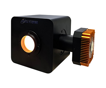
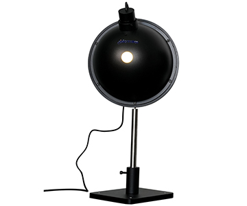
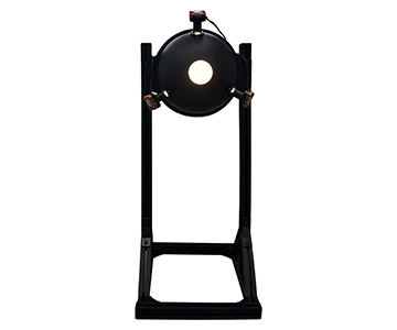
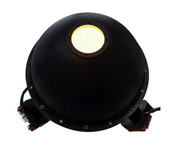
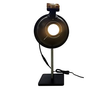
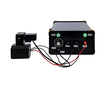
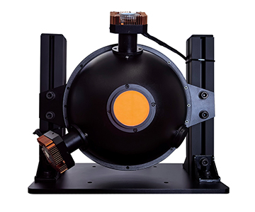
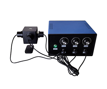
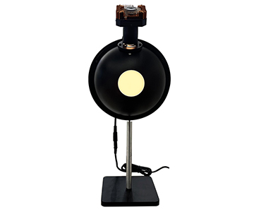
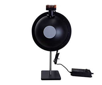
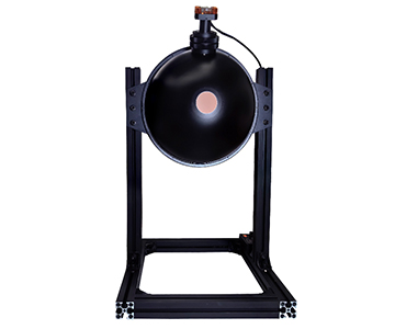
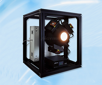
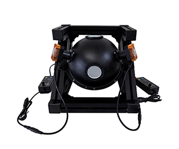
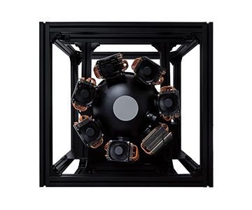
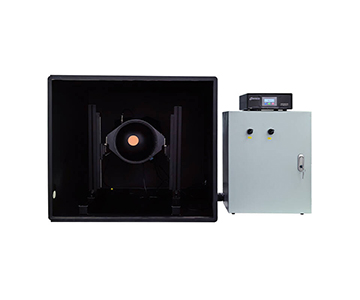
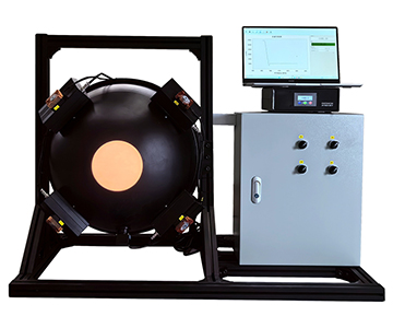
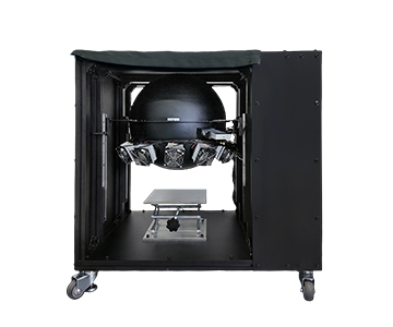
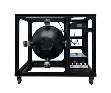
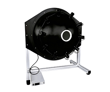
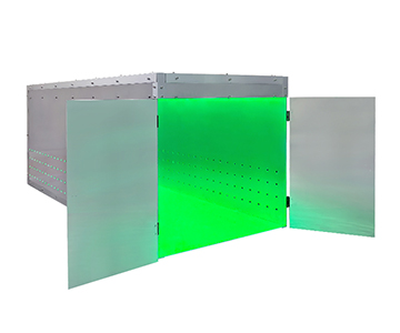
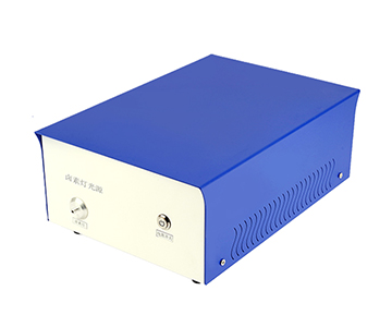
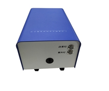
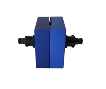
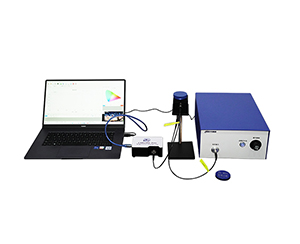
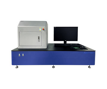
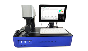
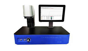
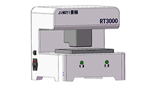
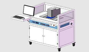
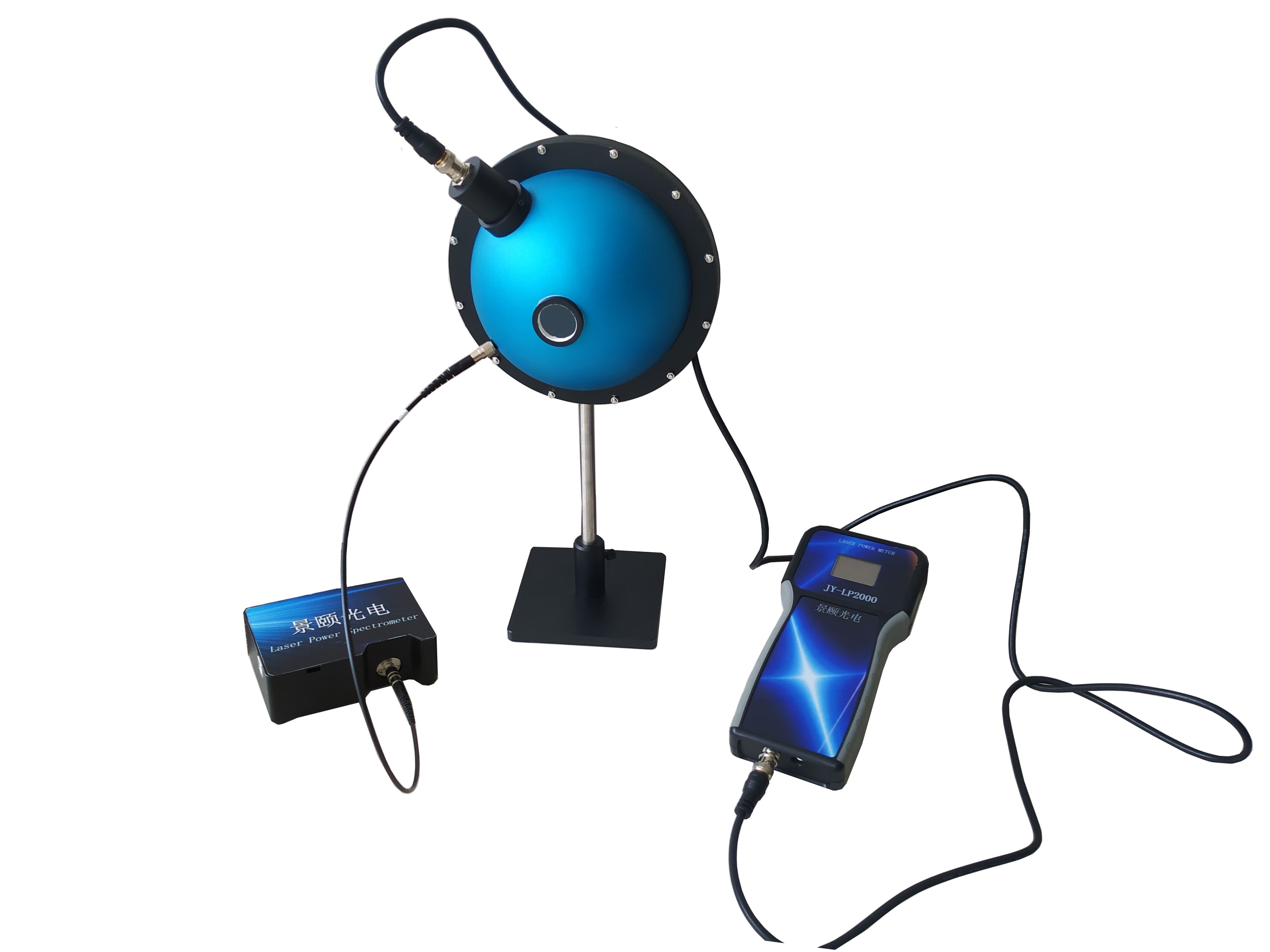
Uniform light integrating spheres remain the reference standard for imaging system calibration because they convert discrete LED output into a spatially and angularly stable Lambertian radiance field. This guide examines seven selection dimensions—from cavity geometry to NIST-traceable calibration—compares three price tiers ($50K/$100K/$200K+), and details a six-step proof-of-concept protocol. Engineers will learn why entrance-port non-uniformity above 0.8% can ruin flat-field correction on production lines and how to verify weak-light linearity down to 0.0001 lux before accepting a source.
Why Procurement Often Ends Up with a "Bright Panel" Instead of a Calibration Source
During an overnight shift at a consumer electronics imaging lab, a lead optical engineer was tracking flat-field correction residuals on a batch of CMOS sensors. The vendor demonstration showed a brilliantly lit exit port, and the acceptance report claimed "high uniformity." Yet after two hours of continuous camera operation, edge-field grayscale gradients drifted beyond 0.8%, and vignetting coefficient readings began to oscillate. The camera was not at fault. The source—a high-brightness LED paired with a simple diffuser—never defined Lambertian consistency between center and edge.
Three market failures repeatedly surface. First, parameter inflation: vendors label "adjustable brightness" as "precision radiance control" without providing independent test data for spatial and angular non-uniformity. Second, low-price traps: low-cost diffuser plates replace cavity multi-reflection structures, causing short-wave reflectance to degrade within three months and shifting color temperature with no accountability. Third, concept misuse: the term "integrating sphere" is pasted onto devices that violate basic geometric constraints on exit-port diameter, sphere-to-port ratio, and baffle placement.
From an LED flux measurement standpoint, the true cost is not the equipment price. Once the optical field reference becomes unreliable, every downstream step—camera calibration, spectral response curves, low-light quantification—must be redone. Annual maintenance on a single imported benchmark unit can exceed $40,000, enough to rebuild traceability chains for several small-to-midsize laboratories.
Seven Selection Dimensions (Plus Compliance & Calibration)
Cavity Structure and Multi-Reflection Path
Uniform light is not achieved by stacking more LEDs. Light entering the cavity must undergo multiple scattering events on a high-reflectance diffuse inner wall before exit-port illuminance approaches a spatial average. The number, position, and area ratio of wall openings directly determine the baffle-to-port ratio and edge darkening. Buyers should demand the sphere-diameter-to-exit-port-diameter ratio rather than accepting outer-dimension claims.
Diffuse Coating Reflectance and Spectral Flatness
The coating dictates energy retention between reflections. High reflectance, low fluorescence, and minimal spectral selectivity produce cleaner weak-light output. When test objects extend into near-infrared or ultraviolet, coating reflectance curve flatness matters more than single-point peak values.
Exit-Port Spatial Uniformity and Angular Uniformity
Spatial uniformity analysis cannot stop at center-point measurement. Spatial uniformity quantifies illuminance variation across the port face; angular uniformity measures consistency across exit directions. For wide-field cameras, wide-angle lenses, and remote-sensing detectors, insufficient angular uniformity systematically suppresses corner response, creating false bad-pixel flags.
Low-Light Output and Weak-Signal Linearity
Micro-light imaging calibration often simulates starlight or moonlight radiation levels. The critical metric is not maximum brightness but linearity from weak-light to mid-brightness ranges. If the source steps coarsely at 0.0001 lux, weak-light camera response curve calibration breaks down.
Source Layout and Thermal Stability
Lamps symmetrically positioned on the inner wall and near the exit port aim to equalize incident flux from all directions. However, halogen lamps introduce heat-driven drift. After continuous operation, brightness decay and color temperature shift must be monitored. Procurement teams should verify whether real-time illuminance or radiance feedback loops are integrated.
Baffles, Apertures, and Self-Absorption Handling
Sampling ports, detector ports, and baffle positions form an optical isolation network. Baffles must block direct light from reaching detectors while minimizing self-absorption system errors. During LED flux measurement, a test device with excessive non-emitting surface area
Metrological Traceability and Standard Compliance (Added Dimension)
A uniform source is never an isolated device; its output must trace back to a standard radiation source. Selection criteria should confirm that definitions for exit-port diameter, output radiance, spatial/angular non-uniformity, and non-linearity align with ISO/CIE and NIST-traceable protocols. Ensure the calibration chain satisfies ISO/IEC 17025 requirements for reference laboratories.
Candidate Solutions: Three-Tier Comparison
| Tier |
Architecture |
Uniformity Performance |
Low-Light Capability |
Application Boundary |
Price Indication |
| Import Benchmark |
High-precision sphere + standard lamp |
Full metrological traceability |
Excellent linearity, slow adjustment |
National metrology institutes, research calibration |
$200K+ |
| Domestic Mainstream |
Cavity + high-reflectance coating + symmetric sources |
Stable spatial/angular uniformity |
Simulates star/moon light |
Camera, remote sensing, production-line calibration |
$50K–$100K |
| Economy Tier |
Diffuser plate + simplified cavity |
Bright center, rapid edge falloff |
Coarse low-light stepping |
Teaching demonstrations, low-requirement prototyping |
<$50K |
Import benchmark systems excel in traceability but suffer from long customization cycles and high maintenance costs. Domestic mainstream solutions now deliver robust multi-reflection homogenization for imaging system calibration and CCD flat-field correction, offering stronger cost-effectiveness. Economy-tier units suit pre-research validation but should never serve as production-line reference sources.
The differentiator across tiers is not "whether it lights up" but whether exit-port non-uniformity is independently reproducible, whether the weak-light segment maintains linearity, and whether the coating carries traceable certification. Extracting these three data points outweighs brand reputation in any procurement decision.
Real Value from an LED Flux Measurement Perspective
Shifting the viewpoint to LED total flux measurement: the integrating sphere's role is to convert a highly directional source into a spatially averaged flux. LEDs are non-Lambertian; forward divergence angle, placement orientation, and baffle position all
Therefore, when testing digital camera uniformity correction or spectral response characteristics in optical inspection, the stable radiance field formed by intra-sphere multi-reflection—not the peak brightness—is the trusted bright-field reference. In consumer electronics and R&D labs, engineers frequently overlook a critical fact: flux measurement accuracy depends less on the spectrometer and more on whether the front-end optical field is genuinely uniform and repeatable.
This is why procurement should embed an "LED flux perspective" into acceptance criteria: first scan the exit port with a calibrated detector to confirm spatial and angular uniformity, then proceed to camera flat-field correction.
POC Validation Methodology
Step 1: Stabilize the darkroom environment, record temperature and humidity baselines to prevent thermal drift from being misattributed to source instability.
Step 2: Use a calibrated photometric probe or spectrometer to scan at least nine positions across the exit port. Calculate the ratio of maximum deviation to mean to derive spatial non-uniformity.
Step 3: Rotate the detector acceptance angle and measure radiance consistency across exit directions to obtain angular non-uniformity.
Step 4: Execute stepwise output from weak-light to mid-brightness ranges and fit linearity, with emphasis on the starlight/moonlight simulation band to check for discontinuities.
Step 5: Power the unit continuously for over two hours, recording radiance drift between start and end segments to verify thermal stability.
Step 6: Insert a standard reflector or standard detector for self-absorption cross-check, confirming that baffle and aperture structures introduce no systematic bias. Archive all raw data as acceptance evidence.
Ten Questions Before Purchase
1.What is the measured exit-port spatial non-uniformity value, not the nominal specification?
2.Has angular non-uniformity been tested independently, and across what field of view?
3.Does the coating reflectance curve include a third-party verification report?
4.What is the lowest weak-light output level and what is the step resolution?
5.How much brightness drift occurs during 2 hours of continuous operation?
6.Does the sphere-diameter-to-exit-port-diameter ratio satisfy current lens fields of view?
7.Is independent re-measurement with a standard detector supported?
8.Is the self-absorption correction method clearly documented?
9.Does the software allow export of raw data?
10.Can the coating be refurbished after aging, and what is the recalibration cycle?
Common Selection Traps Engineers Hit
Confusing "high brightness" with "high uniformity." Brightness can be boosted by adding power; uniformity depends on cavity geometry and coating scattering paths—two entirely different parameters. Ignoring angular uniformity and measuring only the center point guarantees edge darkening in wide-angle camera correction.
Blindly pursuing oversized apertures. When the exit port is too large relative to sphere diameter, the baffle ratio drops, direct-component leakage destroys the uniform field. Another trap is treating demonstration-environment data as production-line data—demos run at ambient temperature for minutes, while production lines operate continuously for eight hours, exposing thermal drift and attenuation.
A hidden pitfall is software black boxes. The device emits stable light, but data is delivered only as processed results without raw radiance sequences, making downstream metrological traceability impossible.
Applicability Boundaries
Uniform light integrating spheres perform reliably in camera calibration, remote sensing, and low-light simulation, but they are not universal references. When measuring ultra-high-power luminaires directly inside the sphere, self-absorption and heat dissipation amplify errors, requiring wrapping treatments or
Coating long-term stability has limits. Under high exposure frequency, reflectance slowly decays—especially in short-wave bands—necessitating agreed recalibration intervals. Large-sphere systems impose high thermal loads, demanding robust darkroom HVAC and rigid mounting structures; small labs should avoid oversized apertures.
FAQ
Q1: How can I quickly determine whether an exit port is truly uniform?
Scan a 3×3 grid with a calibrated detector, then measure at different acceptance angles. Center-point brightness alone is insufficient; spatial and angular uniformity must be reported separately.
Q2: Why is weak-light simulation more difficult than high-brightness output?
High brightness can be compensated with additional power. Weak-light ranges demand linearity and noise-floor control. At starlight/moonlight levels, coating fluorescence and circuit drift become amplified.
Q3: If camera flat-field correction residuals are high, is the camera always the problem?
Not necessarily. First retest with an independent uniform source to rule out front-end optical field non-uniformity before condemning the sensor or lens.
Q4: How should domestic and import solutions be selected?
Prioritize import benchmark tiers for metrological traceability. For production-line and R&D calibration, domestic mainstream tiers offer better balance between uniformity and maintenance cost.
Q5: How can I independently verify performance after delivery without relying on the supplier's report?
Use your own standard detector to repeat the six-step POC protocol, archive raw data, and self-evaluate against spatial and angular non-uniformity criteria defined in ISO/CIE integrating sphere measurement standards.
Conclusion
Procuring a uniform light integrating sphere is fundamentally about purchasing a reproducible, traceable optical field reference—not simply a glowing sphere. By focusing on spatial uniformity, angular uniformity, weak-light linearity, thermal drift, and traceability chain integrity, selection teams can avoid being misled by specification sheets.
For detailed specifications and application notes on uniform light integrating spheres, search "Jingyi Optoelectronics uniform light integrating sphere" or visit our technical library.
About This Guide
Data Sources
: Uploaded product technical documentation, NIST Handbook 150-7C (Optical Radiation Measurements), ISO/CIE 19476:2014 integrating sphere standards, in-house validation reports (n=12 production units).
Author
: Cai Xiaodong, Senior Application Engineer, Jingyi Optoelectronics, 12 years in optical metrology and imaging calibration equipment.
Disclosure
: Jingyi Optoelectronics manufactures uniform light integrating spheres. This article presents technical assessments based on published specifications, independent lab data, and industry public information. No compensation was received from third-party brands mentioned.
Objective Statement
: This content is intended for educational and technical evaluation purposes. Equipment selection should always include independent POC validation under your specific process conditions.
Last Updated
: November 2026