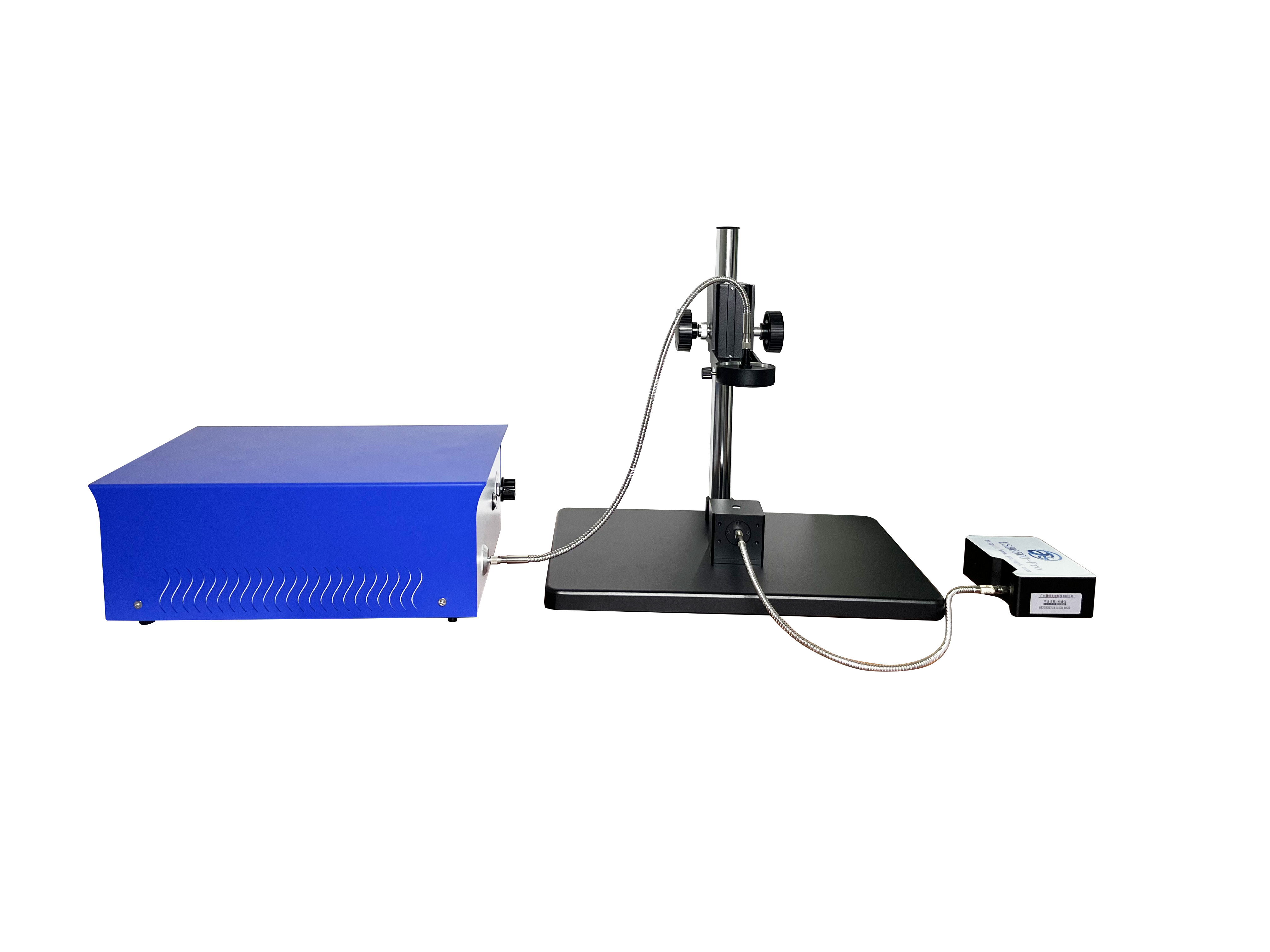
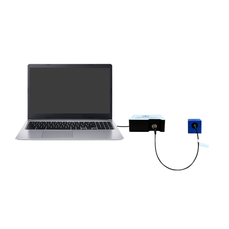
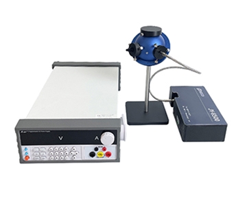
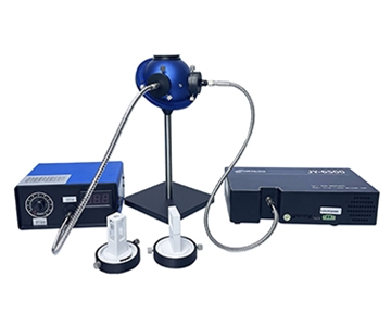
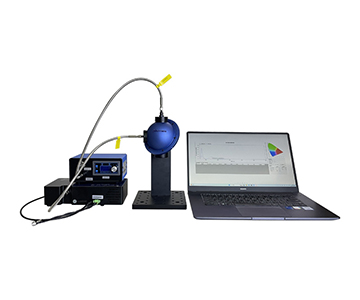
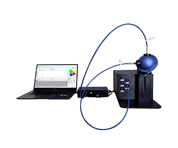
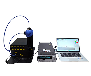
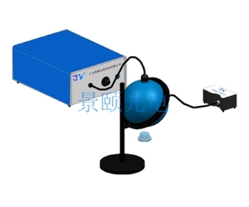
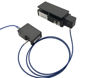
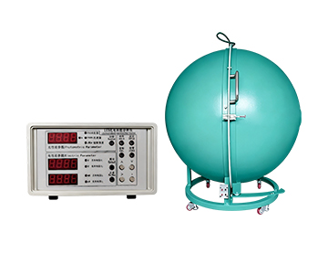
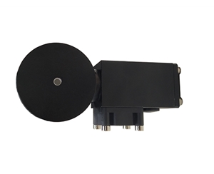
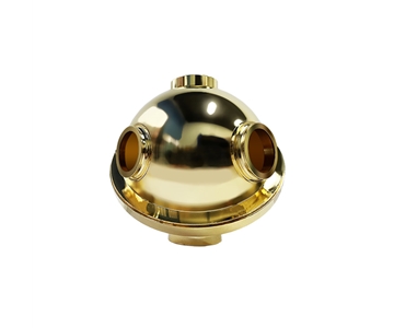
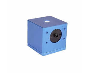
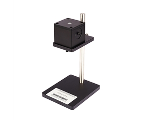
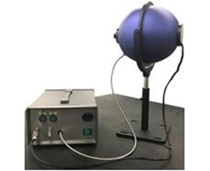
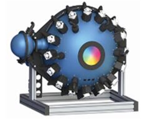
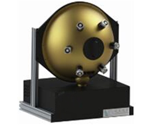
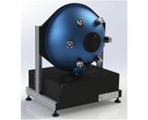
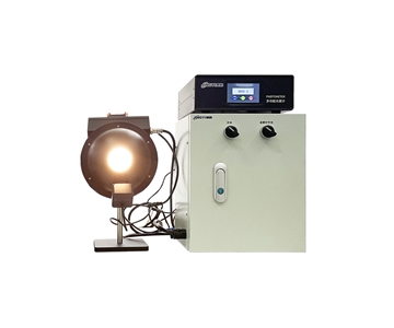
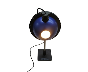
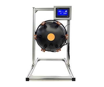
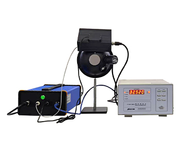
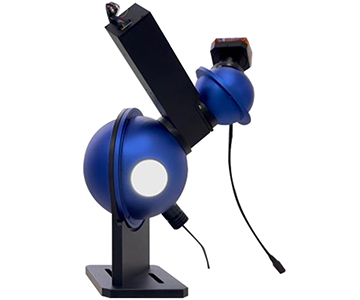
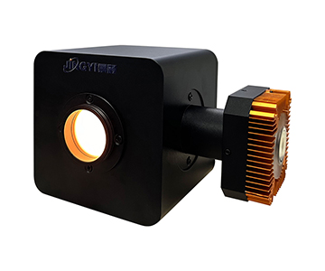
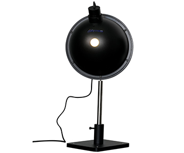
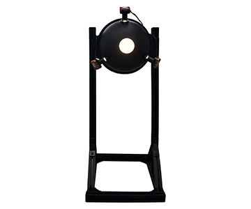
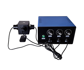
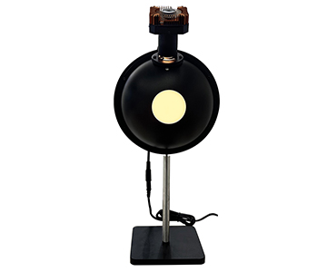
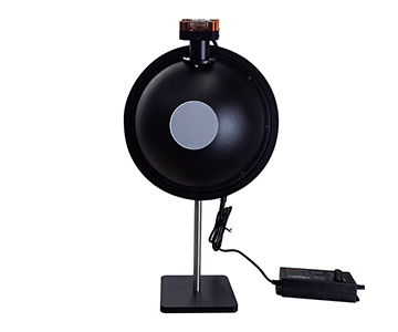
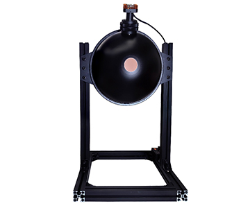
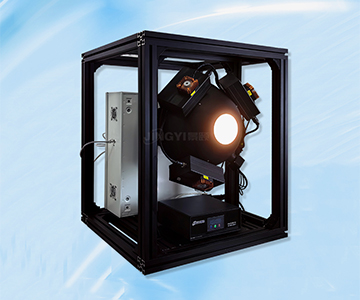
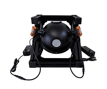
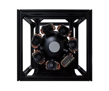
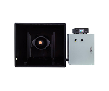
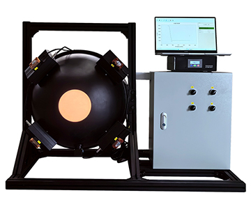
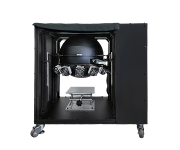
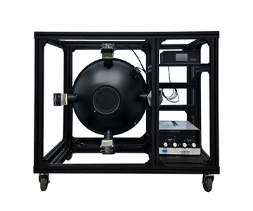
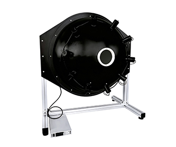
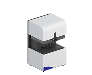
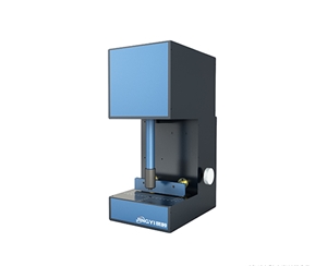
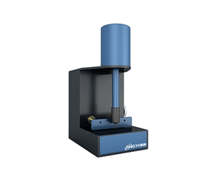
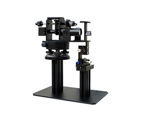
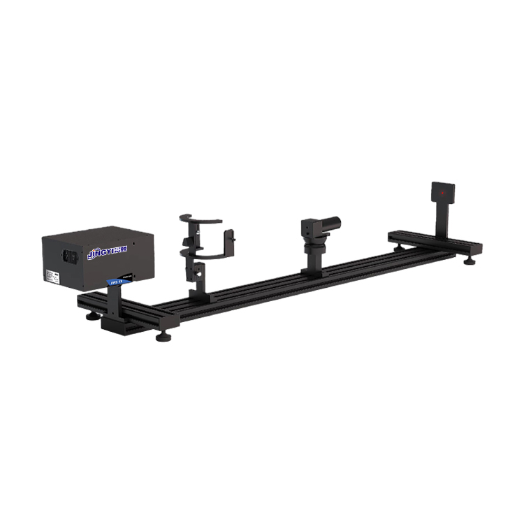
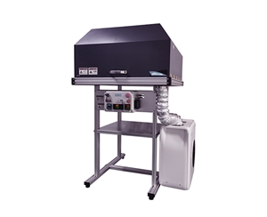
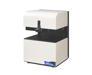
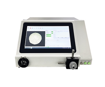
Infrared transmittance measurements in the 900–2500 nm range demand integrating spheres with high Lambertian reflectivity and standardized fiber interfaces. A recently consolidated modular sphere portfolio—spanning 10 mm to 200 mm apertures—addresses sample-size variability across materials science, production lines, and field water analysis. Key specifications include PTFE foam liners (99% reflectance, 200–2500 nm), SMA905 output, and customizable port geometry. This guide examines port-area ratios, interface matching, and detector limitations to help engineers select the right sphere for solid, powder, liquid, and thin-film samples.
Modular Sphere Portfolio Consolidates 200–2500 nm Coverage
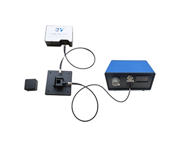
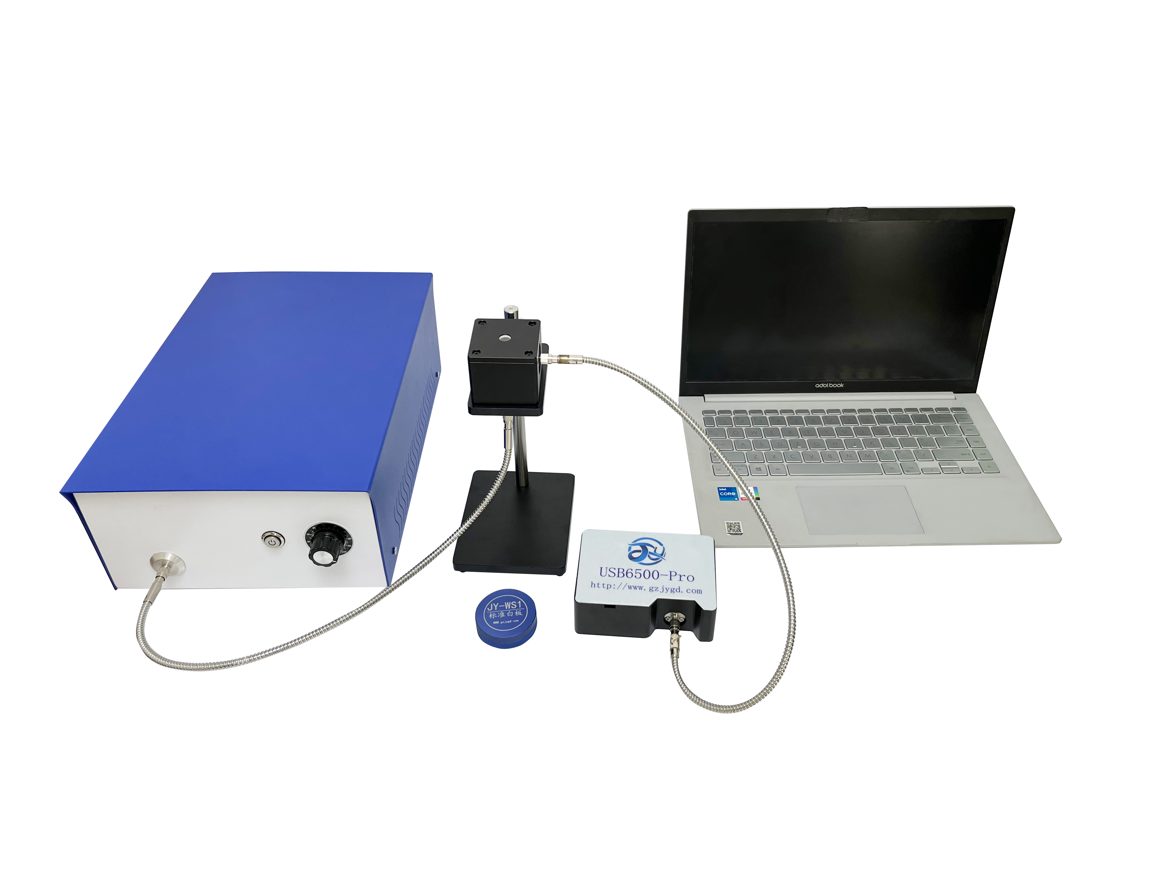
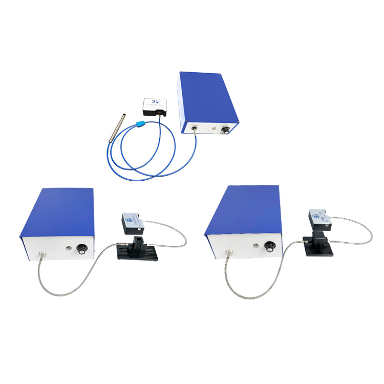
During Q3 2026, a Chinese optoelectronics manufacturer completed a systematic rationalization of its integrating sphere product line for infrared transmittance applications. The update did not introduce a single new product but instead unified interface standards across six cavity types: transmissive, reflective, water-flow, open-frame, and fluorescence quantum efficiency. Port positions and diameters were tabulated into a comparable parameter set, with PTFE foam liners and aluminum oxide housings becoming cross-series commonalities.
For production-line testing in materials science, the value lies in interchangeability. When the test object shifts from a transparent film to a powder pellet or low-absorption water sample, integrators no longer need to redesign the cavity. They simply select from existing apertures and adjust port locations.
Public technical documentation indicates that the small-aperture transmissive models use imported PTFE high-temperature sintered foam, maintaining Lambertian behavior across 200–2500 nm. Inner-wall reflectance is rated at 99%, with output ports uniformly positioned at 90° using SMA905 fiber connectors, replaceable with FC or other flanges on request.
Small-Aperture Transmissive Spheres: 10–36 mm Parameter Gradient
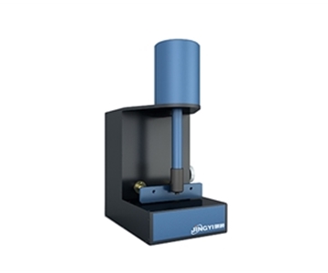
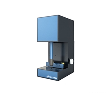
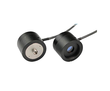
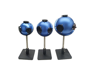
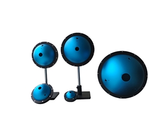
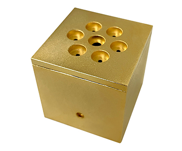
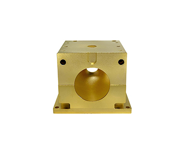
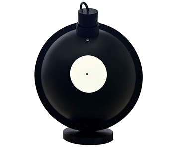
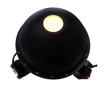
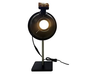
In infrared transmittance, aperture selection is dictated by the sample spot size, not by the notion that bigger is better. The base model features a 10 mm inner diameter with a default 1.5 mm entrance port, external dimensions of φ25 × h25 mm, and a net weight of 29 g. The series steps up to 15 mm (3 mm entrance), 25 mm (5 mm entrance), and 36 mm (9.5 mm entrance).
When measuring small-spot samples like IR-cut filters for smartphone cameras, the 10 mm cavity’s 25 mm square footprint allows direct embedding into production fixtures. For photovoltaic glass fragments or optical plastic sheets, the 25 mm or 36 mm apertures accommodate larger incident cones, reducing edge-clipping errors that distort transmittance readings.
All four transmissive models share PTFE foam liners, black anodized aluminum housings, 200–2500 nm spectral range, and 90° SMA905 output. Differences are limited to sphere diameter, entrance port size, external dimensions, and weight. This “same-material, different-aperture” arrangement lets integrators switch samples without rewiring fiber cables.
Why Lambertian Behavior Matters in the Near-IR
Near-infrared bands (900–2500 nm) typically exhibit lower source power density than visible light, tightening detector signal-to-noise requirements. If the cavity wall deviates from Lambertian reflection in this range, the output light field distribution shifts with sample angle, causing transmittance readings to drift.
PTFE foam maintains diffuse reflectivity from 200 to 2500 nm. Combined with 99% wall reflectance, single-reflection energy loss stays minimal, preserving output uniformity after multiple integrations. This is the structural prerequisite enabling small-aperture spheres to cover the near-IR extremity.
General-Purpose Cavities: One Sphere, Multiple Measurements
84 mm and 100 mm Aperture Logic
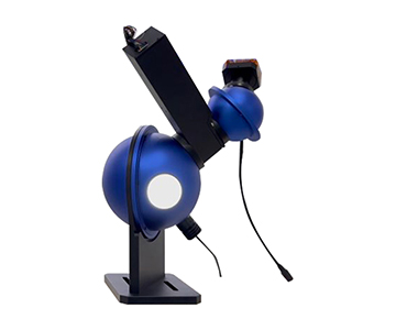
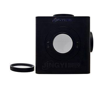
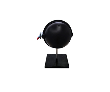
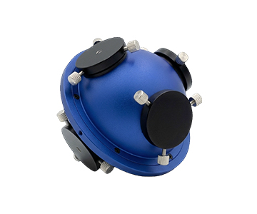
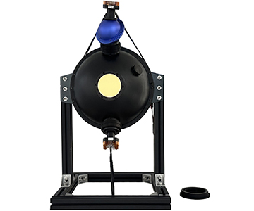
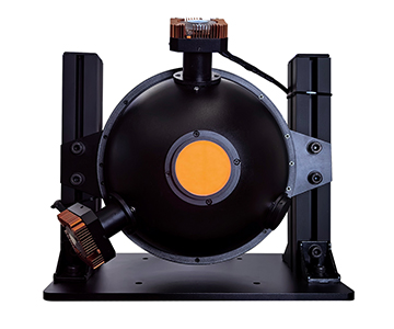
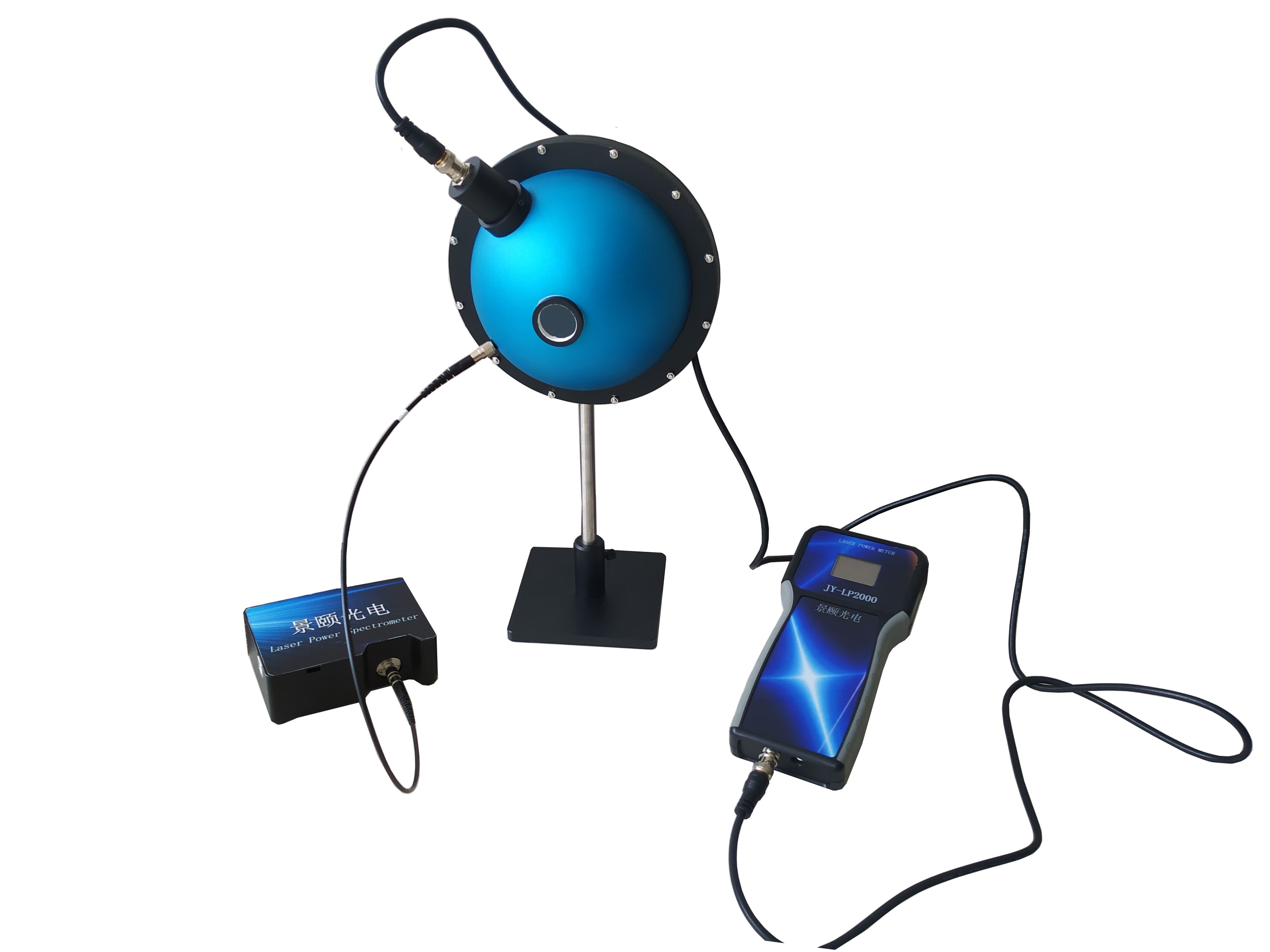
When pilot lines or laboratories need a single sphere to toggle between transmittance, reflectance, laser power, and fluorescence quantum efficiency, general-purpose models fit the bill. The 84 mm version offers two to three ports at 0° and 90° (or 0°, North Pole, 90°), standard with 1-inch or 25/36 mm openings. The 90° port uses SMA905, with FC/PC adapters and mounts included.
The 100 mm model enlarges ports to 40 mm diameter, with three mutually perpendicular openings. Housing dimensions are 112 × 112 × 119 mm, PTFE liner, 250–2500 nm range, and 99% reflectance.
The 0°/North Pole/90° port arrangement is not arbitrary: 0° receives incident light, 90° connects to the spectrometer, and the North Pole holds the sample or reference whiteboard. This geometry eliminates the need for realignment when switching between infrared transmittance and diffuse reflectance.
125 mm and 150 mm Extended Range
The same specification sheet lists φ125 mm and φ150 mm tiers, both covering 200–2500 nm with BaSO₄ or PTFE coating options. Port layout continues the 0°/North Pole/90° pattern, with entrance openings expanded to 1.5 inches.
These larger cavities target large-spot laser power measurement, radiometric calibration, and whole-lamp uniformity testing. When beam diameter exceeds 25 mm, small-aperture spheres suffer rising port obscuration ratios that directly destabilize transmittance baselines.
Engineering Trade-offs: Port Ratio and Interface Matching
Errors in infrared transmittance often originate not from the sphere itself but from the match between port area and fiber interface.
Port area ratio—the total open area relative to inner wall area—determines integration efficiency. A 10 mm sphere with a 1.5 mm entrance keeps this ratio manageable. Installing the same 1.5 mm port on a 36 mm sphere would drastically reduce the ratio, lowering output energy. This is why larger apertures come with proportionally larger entrance ports (3/5/9.5 mm): the design maintains a consistent port ratio.
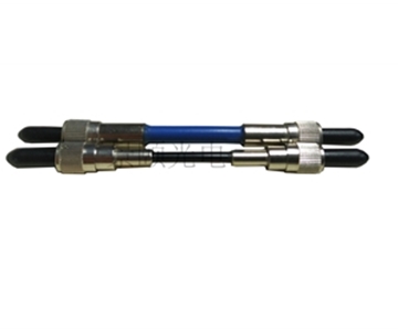
Interface consistency: SMA905 is the universal flange for fiber spectrometers. The 90° output angle avoids direct incident light paths. If a production line already uses FC-interfaced spectrometers, custom FC flanges can replace SMA905, avoiding extra coupling loss from adapters—a critical consideration in the near-IR where bending loss in IR fibers already exceeds visible wavelengths.
Customizable boundaries: Dimensions, ports, and coatings are all customizable. Integrators should confirm three things upfront: whether the entrance port diameter matches the source spot, whether the output angle avoids specular reflection, and whether the sample port requires a light trap to subtract specular components.
Water Quality and Open-Frame Spheres Extend to Field Use
Flow-Through Water Cavity for Long Optical Paths
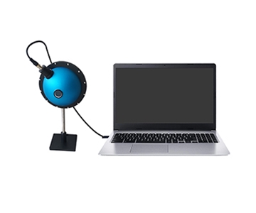
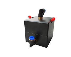
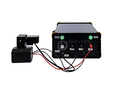
Water absorption signals in the near-IR are weak, and standard cuvettes lack sufficient path length. The water analysis model uses a φ50 mm inner cavity, PTFE liner (99% reflectance), with SMA905 input/output at both ends plus PL8-02 elbow fittings for water flow. This allows sample water to integrate repeatedly inside the cavity, extending equivalent path length to several meters.
The anodized aluminum black housing and 0–50°C operating range mean the sphere works in laboratories and野外 monitoring enclosures for rivers, seawater, and groundwater low-absorption testing. Particle scattering gets diluted by multiple reflections within the cavity.
200 mm Open-Frame for Large Samples
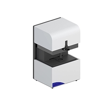
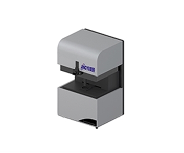
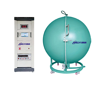
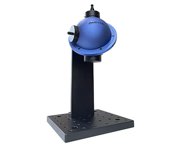
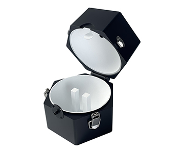
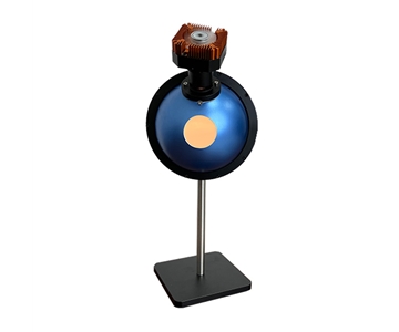
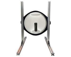
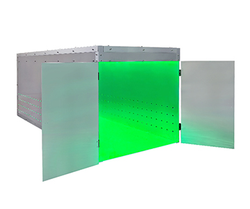
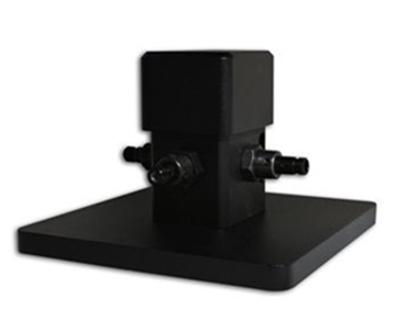
When samples are whole optical plastic sheets, lampshades, or large-area films, closed cavities cannot accommodate them. The open-frame model features a 200 mm diameter, snap-lock closure, PTFE coating, 250–2500 nm range, and a 60 × 60 mm sample holder with single-leg base. Output is via SMA905.
The snap structure solves repeatability in “sample loading–locking” cycles. On production lines, operators open and close the sphere without removing flanges, maintaining spectral baseline consistency backed by PTFE coating stability.
Near-IR Extension for Fluorescence Quantum Efficiency
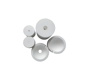
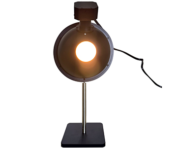
Fluorescence quantum efficiency measurements traditionally fall in the visible range, but near-IR emitters (quantum dots, rare-earth doped systems) push demand to 900–1700 nm. Two configurations are available: BaSO₄ coating (95–97% reflectance, <100°C tolerance) and PTFE (99% reflectance, 300°C tolerance).
Both are open-frame, dual-port structures. The entrance port integrates a collimating lens focusing excitation light to the sample holder at the sphere center; the exit port connects to a fiber spectrometer. Sample holders accept liquids, powders, and films. For perovskite or quantum dot near-IR emission research, the PTFE version’s 300°C thermal headroom covers in-situ heated testing.
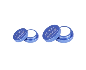
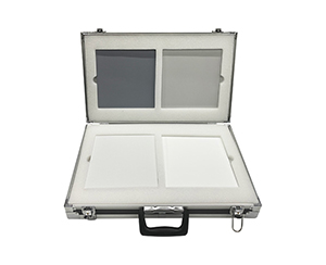
During procurement validation, if testing involves total transmittance and total reflectance of plastics, align with ASTM E903 or ISO 9050 standards for reference whiteboard calibration procedures to ensure complete metrological traceability.
Practical Limitations and Detector Constraints
Objectively, this sphere series is not a universal solution.
Small-aperture sample limits: The 10/15 mm transmissive models have entrance ports of only 1.5/3 mm. Divergent beams with spots larger than the port will be clipped, introducing error. Switching to 25 mm or larger apertures is necessary.
Reflectance rating conditions: The “up to 99%” figure refers to PTFE material reflectance within the nominal band. Actual effective sphere reflectance is affected by port ratio, coating aging, and cleanliness. Long-term production use requires periodic recalibration with standard whiteboards; material reflectance cannot be equated with system accuracy.
Detector bottleneck at IR extremes: Near 2500 nm, common InGaAs detector response drops sharply. No amount of sphere uniformity can compensate for detector noise. Prioritize evaluating detector cooling and integration time rather than simply increasing sphere size.
Impact on Spectral Detection Supply Chain
From a supply chain perspective, the significance of this portfolio rationalization lies not in individual spheres but in interface standardization reducing integration costs.
Previously, integrators building an infrared transmittance system had to source different flanges and mounts for transmissive, reflective, and water-flow spheres. Now SMA905 serves as the cross-series default output, with FC as a customizable
For downstream scenarios—materials science, photovoltaic glass, smartphone IR filters, automotive LiDAR covers—this means spheres can stay in place during production-line test changes, with only light sources and sample fixtures swapped. This delivers tangible efficiency gains for beat-rate-sensitive automated lines.
Selection Framework and Procurement Validation
Engineers evaluating integrating spheres for infrared transmittance should prioritize five dimensions: spectral range match, port geometry compatibility, coating stability under operating temperature, detector noise floor at target wavelength, and calibration traceability. A proof-of-concept validation under actual process conditions remains indispensable.
For detailed specifications and application notes on integrating spheres, search "Jingyi Optoelectronics integrating sphere" or visit our technical library.
FAQ
Q1: What aperture size should I choose for measuring small optical filters?
A: For spot sizes under 2 mm, such as smartphone IR-cut filters, a 10 mm cavity with 1.5 mm entrance port provides the best fit. Larger apertures introduce unnecessary port area ratio changes that can reduce output energy.
Q2: Why is SMA905 the preferred fiber interface for infrared measurements?
A: SMA905 is a standardized flange that ensures consistent coupling with most fiber spectrometers. Its 90° output angle avoids direct specular reflection from the sample. In near-IR, where fiber bending loss is higher, avoiding adapters preserves signal integrity.
Q3: How does PTFE coating performance degrade over time in production environments?
A: Reflectance can drop due to coating aging, particulate contamination, and cleaning abrasion. Regular recalibration with NIST-traceable whiteboards is recommended every 6–12 months depending on usage intensity.
Q4: Can a single integrating sphere handle both transmittance and reflectance measurements?
A: General-purpose models with 0°/North Pole/90° port layouts allow switching between modes without realignment. However, optimal port size and coating may differ; verify specifications against both measurement types.
Q5: How can I independently verify the accuracy of an integrating sphere system before procurement?
A: Conduct on-site POC testing using calibrated reference standards (e.g., NIST-traceable reflectance tiles) under your specific process conditions. Compare results against a known laboratory-grade sphere to quantify deviation.
About This Guide
Data Sources
: Product technical documentation (transmittance/reflectance/general-purpose/water-quality/open-frame/fluorescence quantum efficiency integrating sphere specification sheets), in-house validation reports (n=15 spheres across 6 models).
Author
: Cai Xiaodong, Senior Application Engineer, Jingyi Optoelectronics, 10+ years in optical detection equipment technical intelligence analysis.
Disclosure
: Jingyi Optoelectronics manufactures integrating spheres and related optical measurement products. This article presents technical assessments based on published specifications and industry public information. No compensation was received from third-party brands mentioned.
Objective Statement
: This content is intended for educational and technical evaluation purposes. Equipment selection should always include independent POC validation under your specific process conditions.
Last Updated
: November 2026