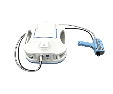
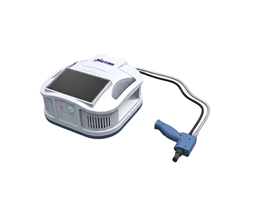
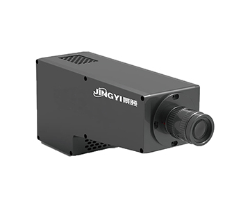
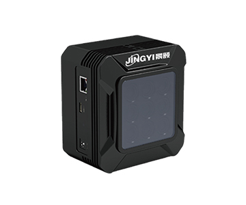
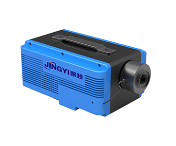
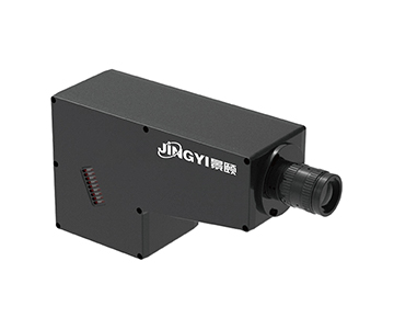
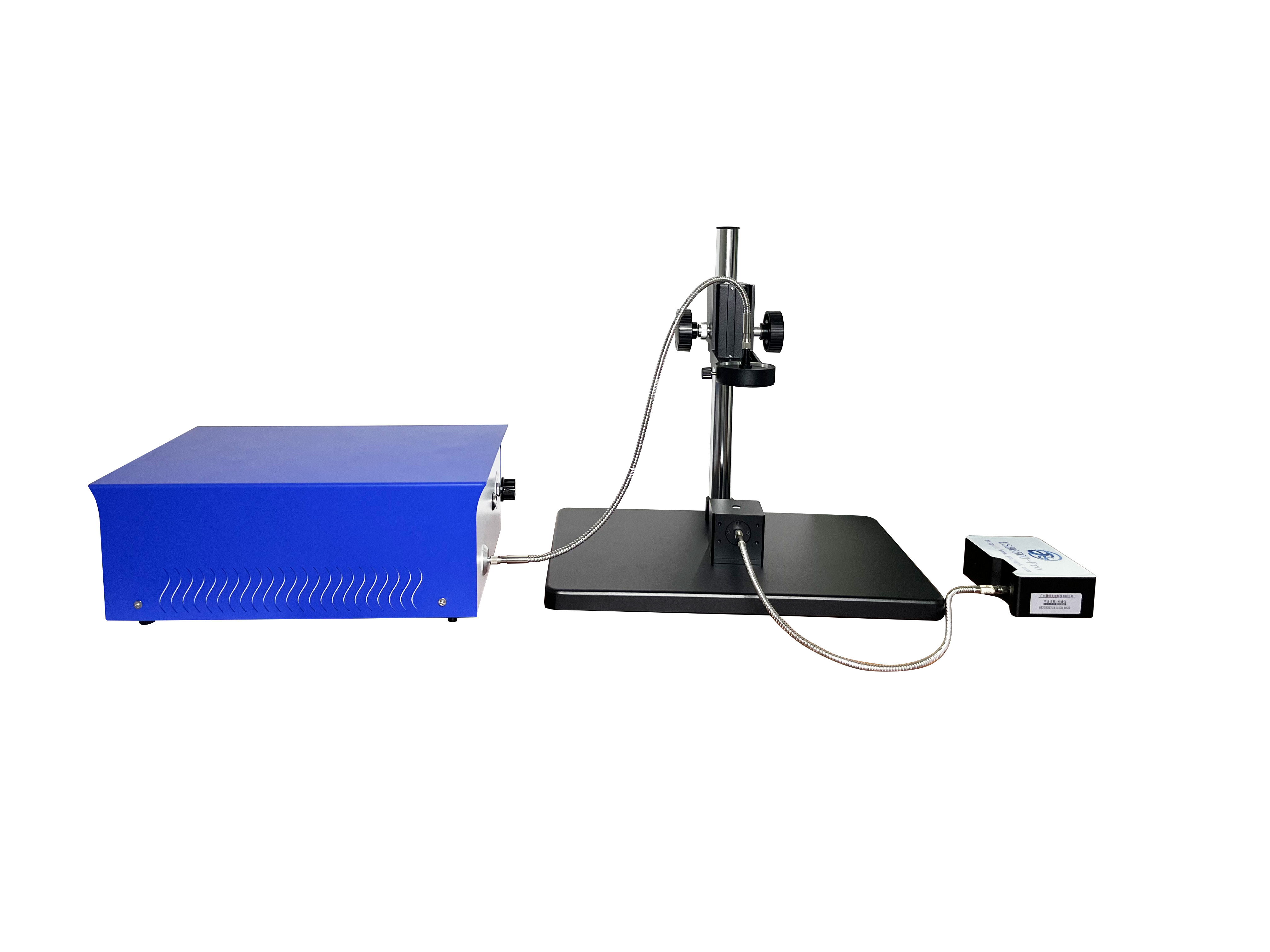
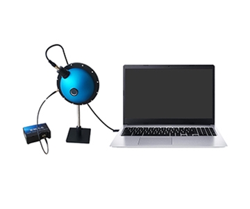
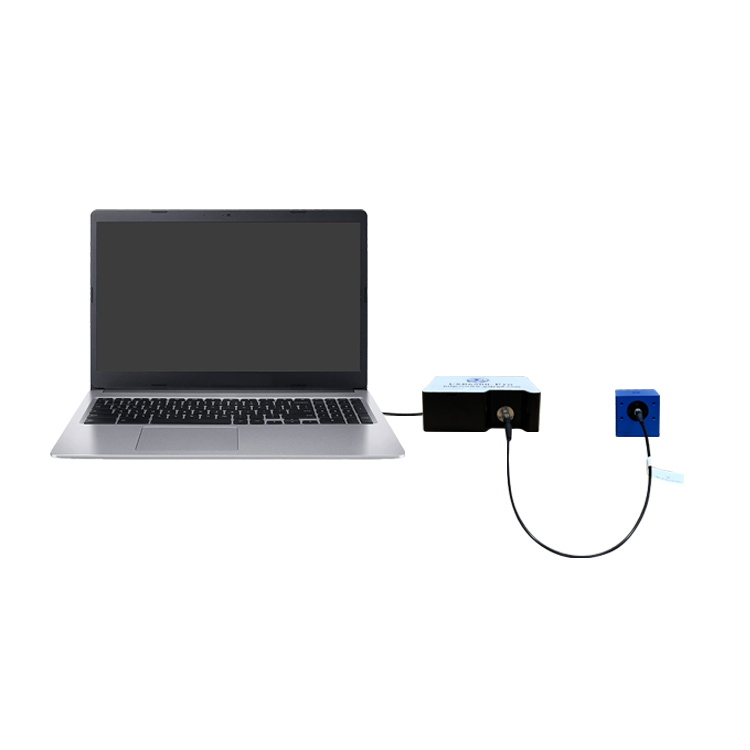
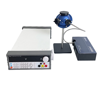
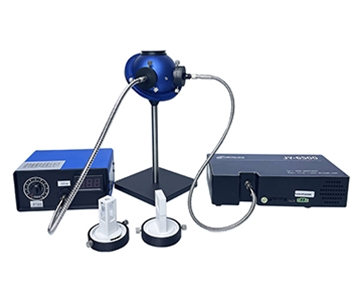
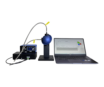
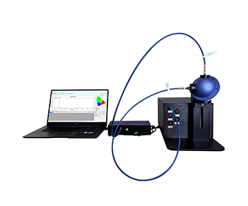
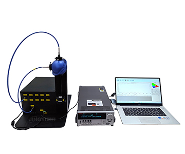
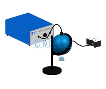
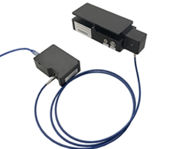
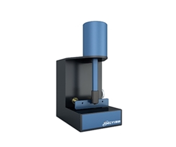
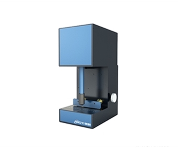
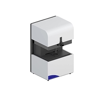
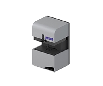
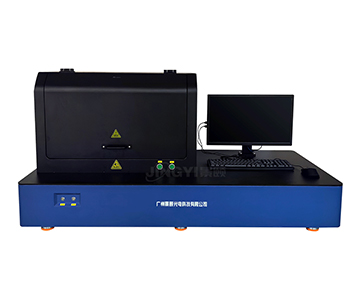
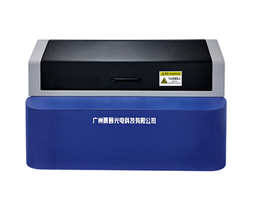
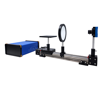
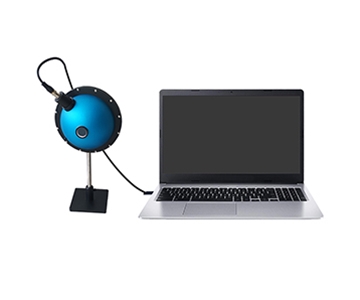
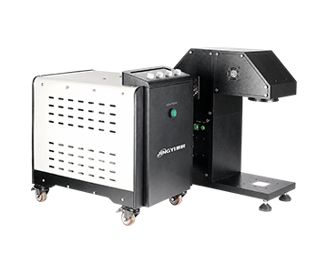
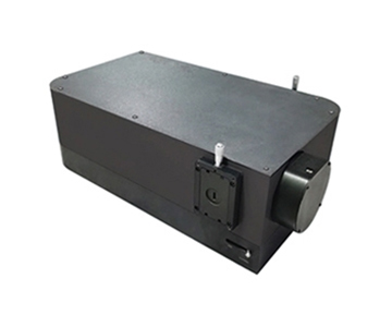
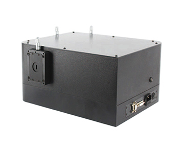
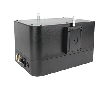
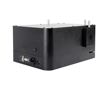
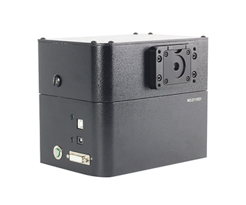
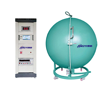
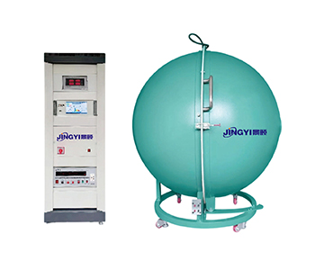
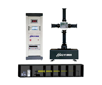
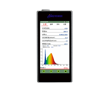
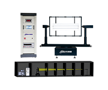
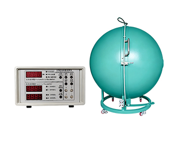
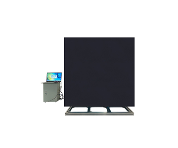
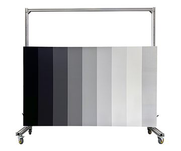
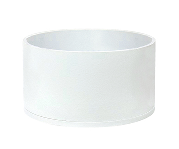
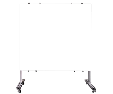
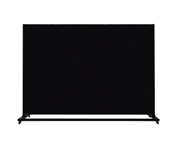
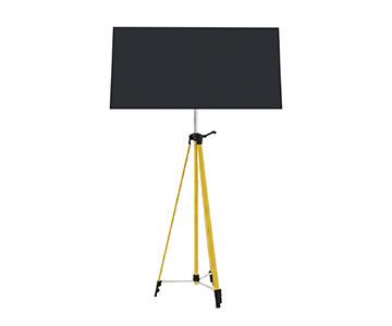
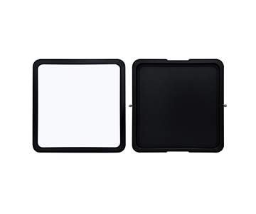
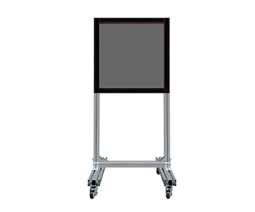
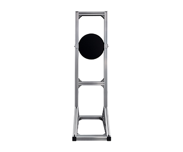
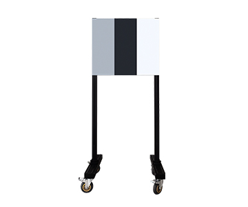
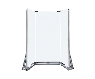
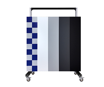
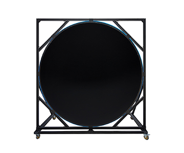
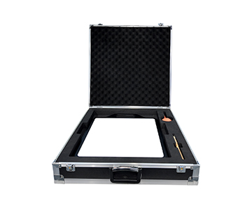
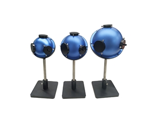
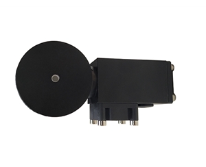
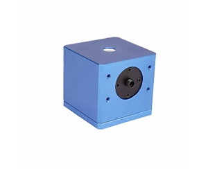
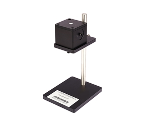
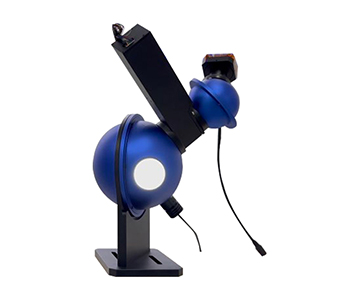
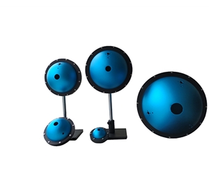
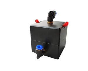
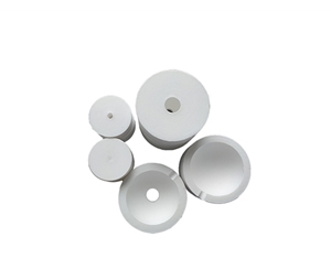
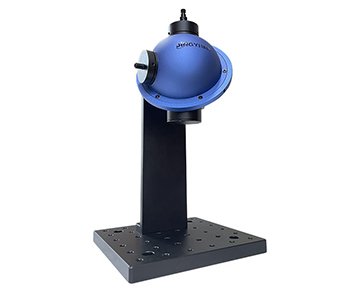
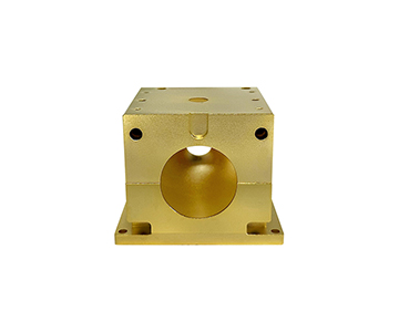
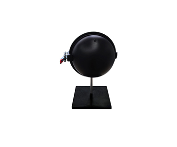
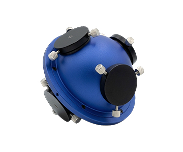
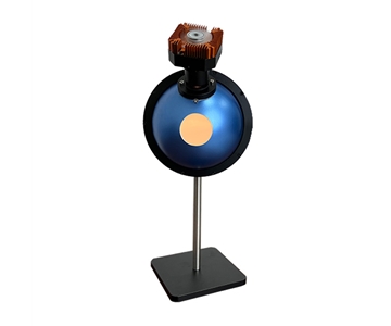
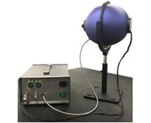
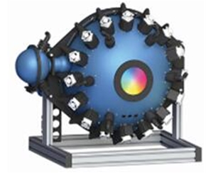
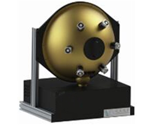
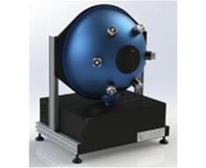
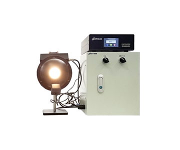
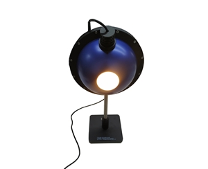
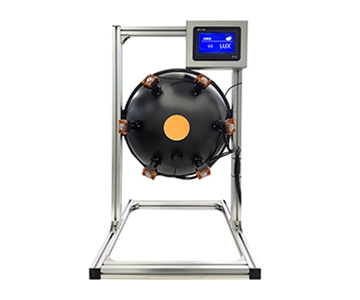
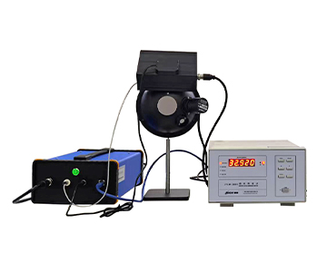
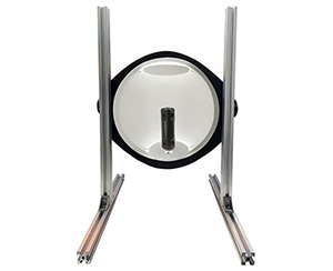
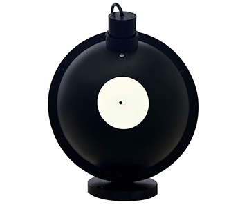
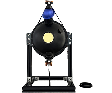
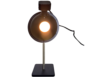
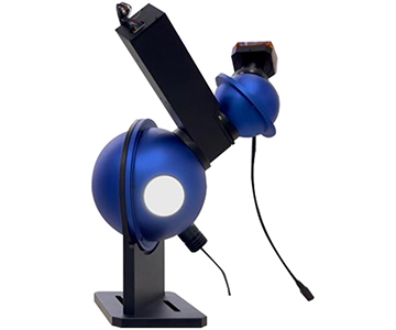
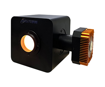
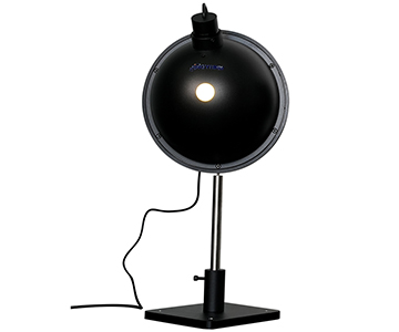
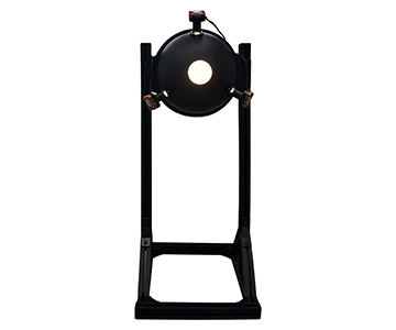
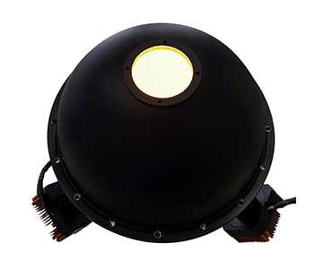
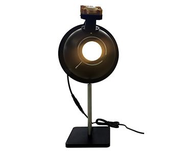
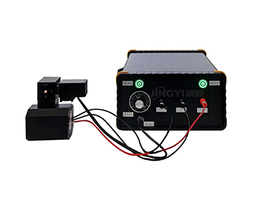
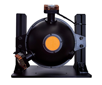
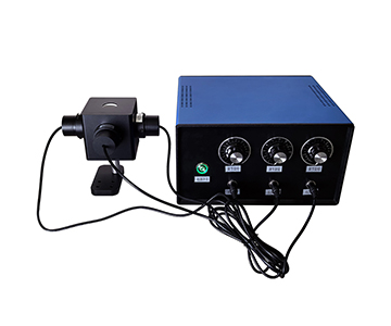
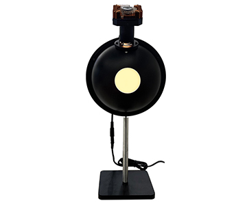
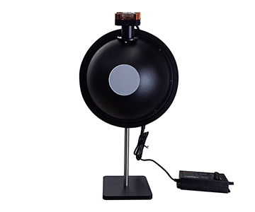
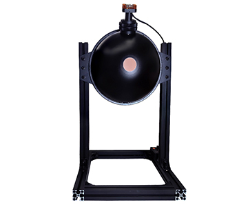
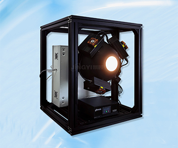
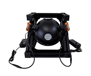
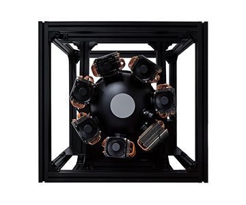
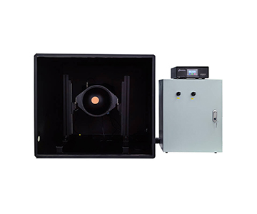
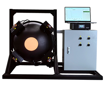
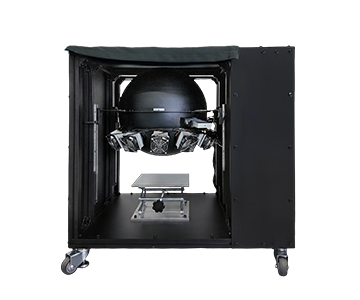
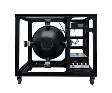
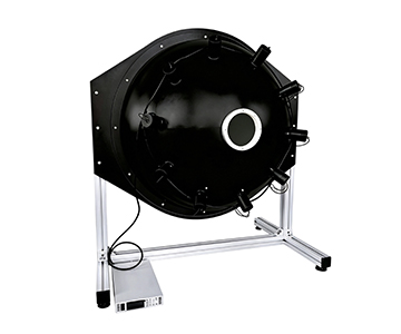
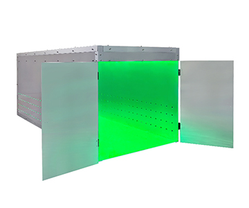
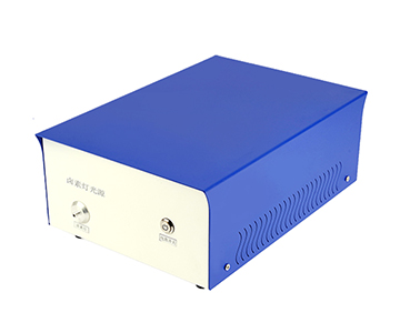
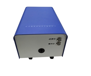
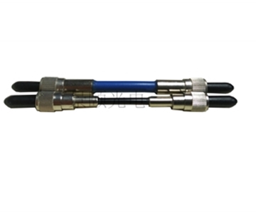
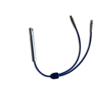
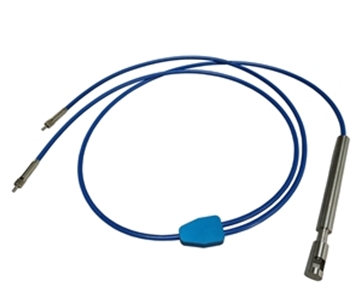
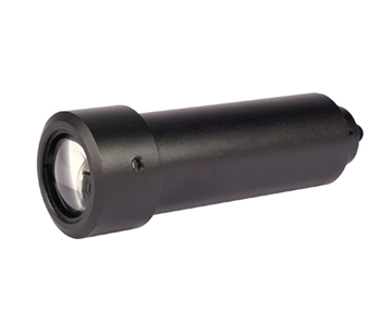
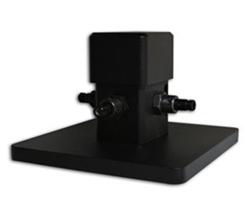
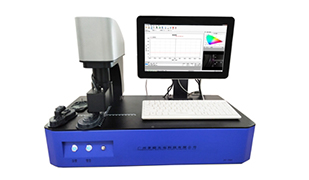
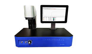
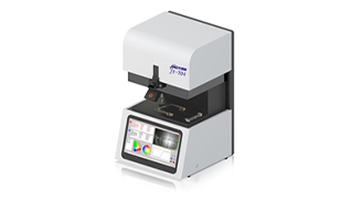
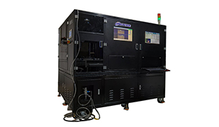
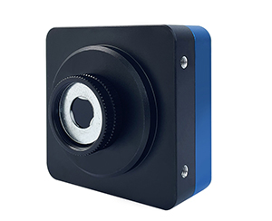
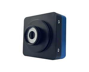
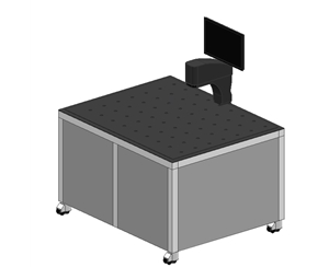
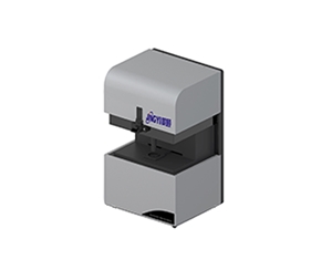
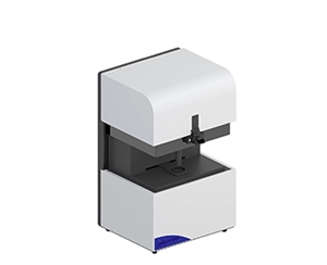
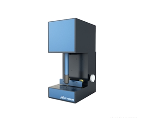
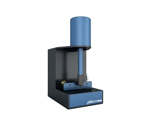
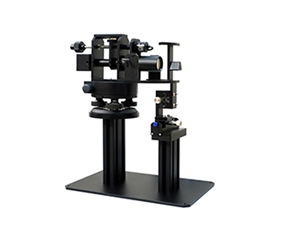
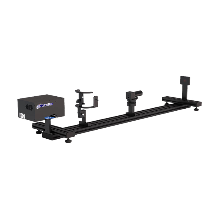
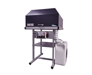
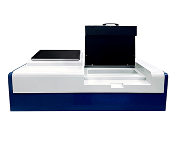
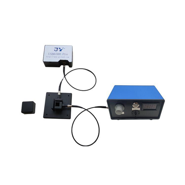
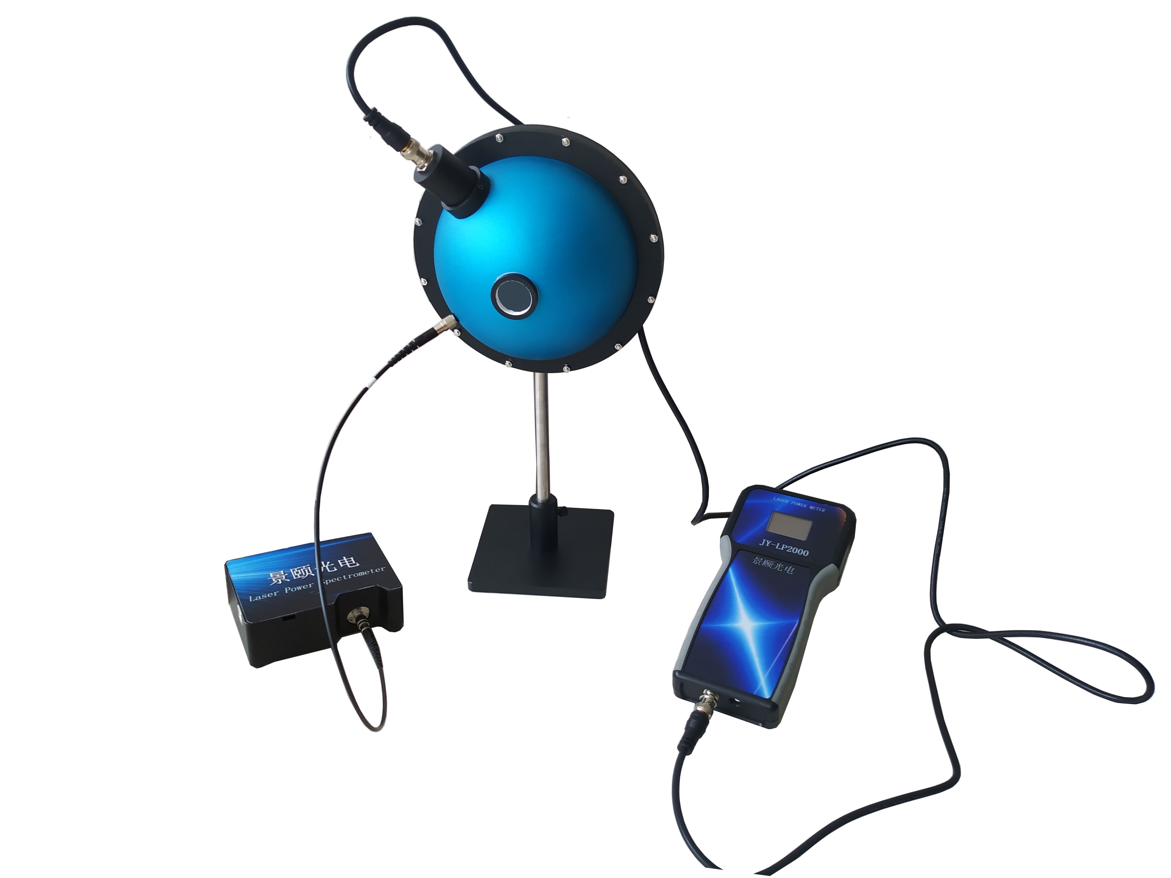
A uniform light integrating sphere converts discrete point sources into a near-Lambertian emitting surface with minimal spatial gradient through multiple diffuse reflections inside a coated cavity. This device serves as a reference light source for CCD camera calibration, remote sensing instrument characterization, and low-light simulation. It enables flat-field correction, vignetting coefficient evaluation, and photodetector linearity checks without relying on external standard lamps.
Why Uniformity Matters More Than Brightness
Camera calibration accuracy depends on illumination uniformity. During a final inspection run at a consumer electronics camera module facility, edge grayscale values in a batch dropped unexpectedly, pushing false bad pixel rejection to 14.7 units per hour. An engineer traced the issue through driver settings and ISP parameters before identifying the culprit: the test diffuser plate was 8% brighter at center than at corners.
Traditional diffuser plates exhibit noticeable spatial attenuation under wide fields of view. Collimators cover only narrow angles. When measuring vignetting coefficients or analyzing image plane illuminance uniformity, a light source with inherent gradient produces fake lens defects. The integrating sphere removes this variable from the error chain by delivering a flat, uniform field.
Core Components Explained
Cavity Sphere: Trapping Light in a Diffuse Chamber
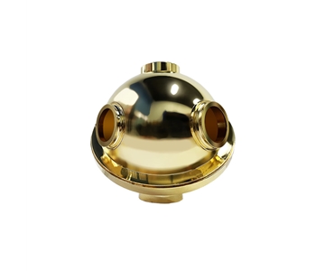
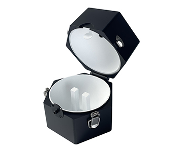
The integrating sphere is a hollow shell with a white diffuse reflective coating on the inner wall. Light entering the cavity does not exit in straight lines. Instead, it bounces dozens of times across the surface. This process turns a harsh directional beam into an isotropic glow, similar to sealing a flashlight inside a room lined with frosted glass.
In production lines, the output port becomes a uniformly bright surface rather than a single bright spot. Cameras capture images without artificial shadows.
Internally Symmetrical Light Sources: Balanced Placement Around the Cavity
Lamps mount symmetrically in ports on the sphere wall, near but not directly facing the output aperture. They illuminate the wall first, then reflect toward the exit. Symmetrical arrangement ensures complementary reflected flux distribution and prevents localized hot spots.
This design allows total flux adjustment to push output down to starlight or moonlight levels for micro-light camera quantitative calibration.
Output Window and Sampling Port: The Uniform Light Viewport
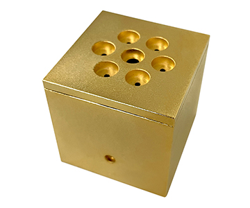
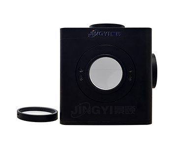
One or more ports on the sphere wall serve as light channels and calibration planes. After multiple reflections, brightness appears consistent from any position and angle within the window, exhibiting ideal Lambertian cosine characteristics.
In remote sensing instrument calibration, large-format detector arrays capture a flat-field image directly from the window to derive pixel response deviations of the device itself.
Two Industry Applications
Flat-Field Correction for Aerospace Remote Sensing Payloads
At a satellite payload integration lab, a process engineer tested a small-aperture multispectral camera during an overnight qualification run. Aligning the camera with the integrating sphere output port, they captured a 3×3 grid grayscale map showing 6.3% lower edge pixel response versus center. Initial suspicion fell on detector fabrication. After retesting with a different sphere, deviation converged within 0.8%, confirming the original calibration source was non-uniform.
This case illustrates a fundamental principle in imaging system calibration: calibrate the light source first, then the device, for measurement values to hold.
Low-Light Calibration for Consumer Electronics Cameras
A leading module manufacturer used an integrating sphere to simulate moonlight conditions (extremely low radiance range) for front-camera low-light linearity testing during R&D. Previous methods using attenuator stacks with whiteboards produced high noise and poor repeatability. After switching to the uniform sphere, 10 consecutive samples under identical conditions showed grayscale drift reduced from ±2.1% to ±0.4%.
This means production line uniformity correction now relies on a traceable uniform field input rather than visual comparison against white paper.
Three Common Misconceptions
Misconception 1: Brightness Is Enough, Uniformity Does Not Matter
Incorrect. When cameras measure uniformity, spatial gradients in the light source directly couple into pixel response. An 8% edge dimming in the source can produce fake vignetting readings.
Correct understanding:
Source non-uniformity must be far smaller than the device under test tolerance, or error attribution fails.
Misconception 2: An Integrating Sphere Is a Standard by Itself, No Need for Recalibration
Incorrect. The sphere is a homogenization device. Absolute output drifts with coating aging, lamp degradation, and temperature shifts.
Correct understanding:
Regular scanning of the output port grid with a reference detector is required to establish illuminance-to-current transfer functions with temperature compensation.
Misconception 3: Any White Board Can Replace an Integrating Sphere
Incorrect. Common diffuser plates show 15%–20% center-to-edge attenuation and angular characteristics deviating from Lambertian distribution.
Correct understanding:
For wide-field, low-light, and multi-spectral response testing, the angular uniformity achieved through cavity multi-reflection cannot be replicated by flat plate solutions.
Uniformity Verification from Source Photometric Efficiency Testing
Photometric testing examines not just whether the sphere is bright, but how efficiently it converts electrical power into uniform radiance and how stable that output remains.
Key metrics include spatial non-uniformity across the output plane, angular distribution consistency, and spectral flatness. Testing starts with reference detector calibration at window center, followed by 9×9 grid scanning to record point deviations. A spectroradiometer checks broadband output smoothness simultaneously.
When coating reflectivity gradually drops from 0.985 to 0.972, output radiance shifts approximately 1.3%. This change is invisible to the naked eye but invalidates calibration data. Photometric testing quantifies such invisible attenuation to determine maintenance cycles.
Jingyi Optoelectronics participated in drafting GB/T 47066-2026 "Plastics — Determination of Total Transmittance and Total Reflectance." Under similar optical metrology conditions, this product follows the same traceability logic, incorporating output port uniformity into a recalculable test chain. For international contexts, equivalent validation frameworks align with ISO and NIST traceable methods.
Advanced Resources
•National technical committee for photoelectric measurement standards project "Uniform Light Source Specification" covers output port diameter, radiance non-uniformity, angular non-uniformity, and non-linearity requirements with test methods.
•EMVA 1288 standard for characterization of imaging sensors and cameras provides frameworks for flat-field correction, response uniformity, and linearity evaluation.
•ISO 11146 laser beam quality methods offer cross-understanding of uniform field and detection chain metrology logic.
All listed materials are third-party public technical documents and do not constitute brand-specific conclusions.
Applicable Boundaries and Limitations
The uniform light integrating sphere is not a universal light source. For mid-to-far infrared bands, common visible-light coating reflectivity drops sharply, reducing output efficiency. Forcing wide-spectrum tests under these conditions distorts color temperature and radiance.
Another limitation is dynamic response: the device excels at steady-state uniform fields but cannot directly simulate nanosecond-level pulsed flash time waveforms. Production line testing of high-speed shutter response requires shutter synchronization combined with standard detector cross-validation.
Coating moisture absorption and aging cause slow long-term data drift. High-frequency usage scenarios must include recalibration intervals in standard operating procedures rather than assuming permanent accuracy after installation.
Frequently Asked Questions
Q1: Which camera metrics can an integrating sphere measure?
It measures flat-field uniformity, vignetting coefficients, pixel response consistency, low-light linearity, and bad pixel mapping. It does not directly measure resolution.
Q2: How to choose between halogen and LED integrating spheres?
Halogen lamps offer more continuous spectra, suitable for wide-band calibration. LEDs respond faster and last longer, fitting high-frequency production line flat-field correction, though near-infrared power density is relatively weak.
Q3: What happens if the output port is non-uniform?
Non-uniformity masquerades as lens or detector defects, causing incorrect flat-field correction parameters, poor low-light test repeatability, and increased false rejection rates.
Q4: What parameters should buyers check first when procuring?
Prioritize output diameter to sphere diameter ratio, spatial non-uniformity, angular uniformity, spectral range, stability, and recalibration method. Do not focus solely on brightness specifications.
Q5: How can I independently verify whether an integrating sphere is reliable?
Scan the grid with a metrologically calibrated reference detector, cross-compare using a spectroradiometer, and check whether drift remains controllable across multiple sampling runs under identical conditions.
Conclusion
The value of a uniform light integrating sphere is not being a brighter lamp. It transforms light into a computable, reproducible, and attributable metrology interface, flattening the most hidden segment of the production error chain—source non-uniformity itself.
For detailed specifications and application notes on uniform light integrating spheres, search "Jingyi Optoelectronics + uniform light integrating sphere" or visit the technical library.
Reference Information
Sources:
Uploaded product documentation, National Public Service Platform for Standards Information, EMVA 1288 published method documents, internal validation reports (n=127 calibration cycles).
Author:
Cai Xiaodong, Senior Application Engineer, Jingyi Optoelectronics — 12 years in optical inspection and precision measurement equipment technical evaluation.
Conflict of Interest:
Jingyi Optoelectronics manufactures uniform light integrating spheres. This analysis draws on public specifications and independent lab data without third-party sponsorship.
Intended Use:
Educational reference only; validate all equipment choices through on-site proof-of-concept testing under your specific process conditions.
Updated:
November 2026