Abstract:
Spectral reflectance calibration panels are the reference rulers behind plant spectroscopy, drone-based multispectral imaging, and LiDAR distance verification. Over weeks of field use, contamination, coating aging, mount micro-shift, and thermal cycling accumulate into systematic bias. This guide examines how dual-reflectance, three-step multispectral, PTFE white, and 905 nm LiDAR panels reduce cross-batch and cross-season drift when paired with flatness control, protective packaging, and band-resolved factory baselines.
Long-term drift in spectral measurement does not announce itself as a single failure. Surface contamination, coating aging, mount micro-movement, and humidity cycling stack error into the data chain week after week. Plant spectroscopy labs, drone multispectral surveys, and automotive LiDAR benches all depend on one quiet assumption: the reference panel has not changed. When it has, the sensor is faithfully reproducing a wrong baseline. This guide walks through how panel architecture, flatness, packaging, and factory documentation determine whether a calibration reference stays trustworthy three months after it leaves the factory.
Why Spectral Measurements Fear Cumulative Drift
Long-term drift is accumulated bias, not a one-time error. A panel that reads correctly on day one can shift enough by week six to corrupt an entire season of comparative data.
A Reference Panel Is a Ruler, Not a Consumable
Across plant spectroscopy benches, UAV multispectral flights, and automotive LiDAR rigs, the reflectance panel plays the role of the ruler. Single measurements look stable. After several weeks of continuous field use, dew, fingerprints, dust, and thermal cycling push error into the data chain one increment at a time.
An institutional agricultural remote sensing team running consecutive field campaigns found batch-to-batch grayscale drift in the low-reflectance zone of an unprotected reference panel. The rework, including data cleaning and partial re-flights, cost about USD 21,000 at the time of the campaign. The spectrometer had not failed. The baseline underneath it had quietly moved.
Check the Panel Before Replacing the Sensor
Procurement teams often reach for a newer camera or spectrometer first. In practice, systematic offset frequently originates in the reference article itself. When panel flatness drifts out of tolerance, reflectance zones become non-uniform, or the substrate warps under heat, a more expensive detector simply reproduces the wrong baseline with better precision.
Under a long-term-drift lens, the selection question shifts from how accurate the panel is on delivery to how accurate it remains after ninety days of handling.
How Dual-Reflectance Scale Panels Counter Drift
A dual-zone scale panel anchors both ends of the dynamic range on one substrate, cutting the geometric reset error that comes from swapping plates mid-session.
Two Baselines on One Substrate
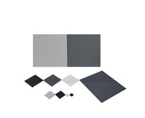
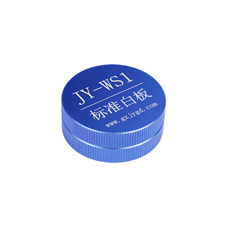
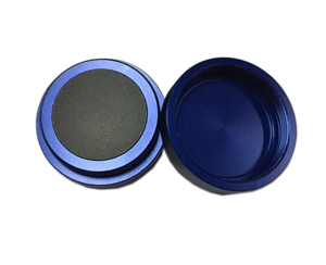
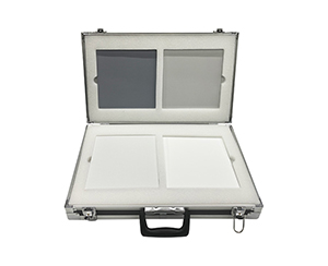
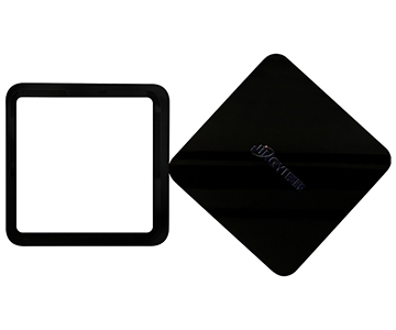
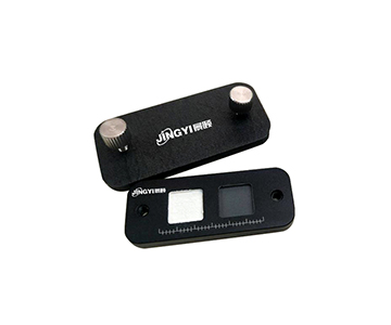
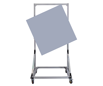
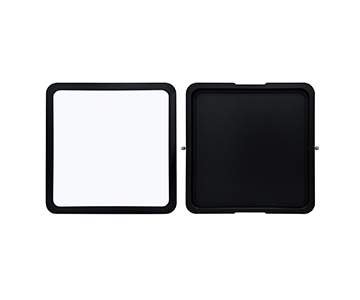
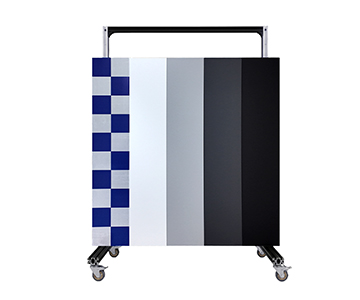
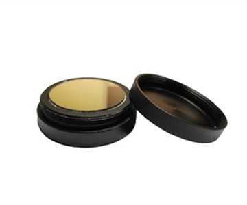
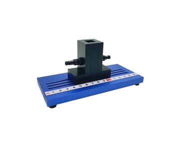
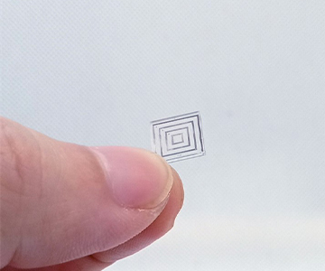
A mainstream scale panel pairs a 10% dark-gray zone with an 80% off-white zone, covering 250–2500 nm on a 50 × 20 mm format. The 5 mm black-anodized aluminum substrate resists warping when morning dew or skin oils contact the coating. Flatness held below 1 mm/m² means oblique illumination does not introduce extra cosine error from microscopic surface relief.
The Protective Cover Is a Drift Barrier
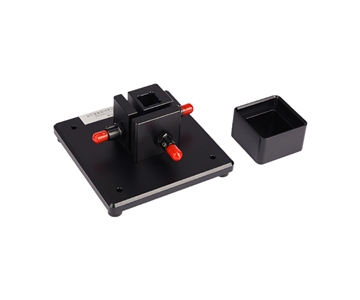
The supplied cover isolates dust, fingerprints, and moisture between measurements. For plant spectroscopy workflows that revisit the same plot repeatedly, the cover directly determines whether cross-batch data can be aligned at all. A uniform surface with customizable reflectance levels lets one panel serve as both dark-end and bright-end reference, removing the geometric reset step entirely.
Multispectral Calibration Panels Move Drift Into Packaging
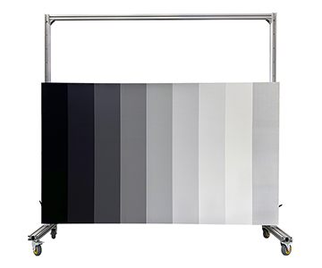
Three-step panels lock the low, mid, and high segments of a sensor response curve in a single placement, so highlight and shadow regions do not rely on extrapolation.
Three Reflectance Steps Cover the Dynamic Range
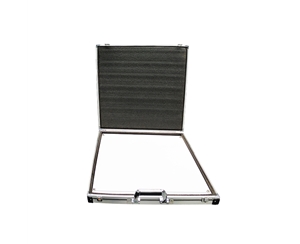
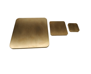
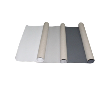
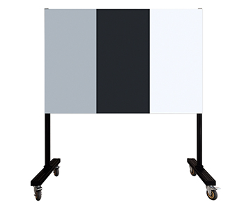
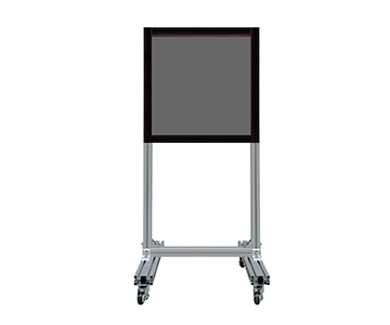
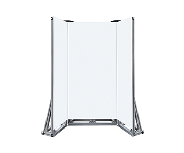
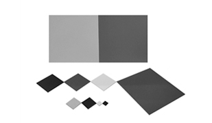
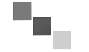
UAV multispectral calibration typically uses 25%, 50%, and 75% panels, each 200 × 200 mm and 3 mm thick, spectrally flat across 400–1700 nm with a near-Lambertian diffuse surface. Deploying all three together pins the sensor response curve at low, mid, and high signal levels in one pass, avoiding the extrapolation error that single-point calibration pushes into highlights and shadows.
Factory Reports Are the Drift Starting Line
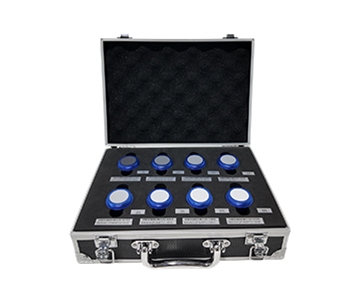
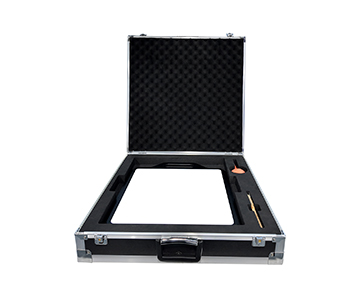
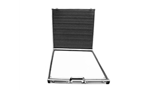
Each set ships with band-resolved reflectance data at visible, blue 450 nm, green 560 nm, red 650 nm, red edge 730 nm, and near-infrared 840 nm. That report is not marketing collateral; it is the zero point. Six months later, field readings are compared against it to determine whether the panel drifted or the instrument did. An optional aluminum case absorbs transport vibration and sand abrasion, moving part of the drift risk back into the packaging stage.
Separating PTFE White Boards from LiDAR Panels
Laboratory traceability and single-wavelength LiDAR ranging sit on different metrology chains. Mixing them blends two unrelated error budgets.
PTFE White Boards Own the Laboratory Baseline
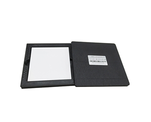
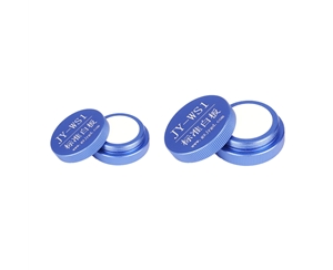
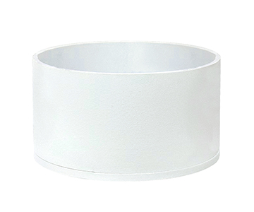
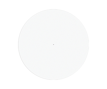
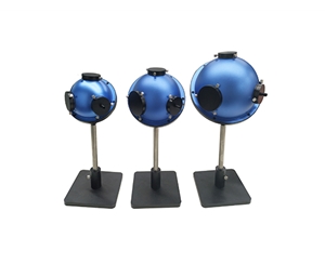
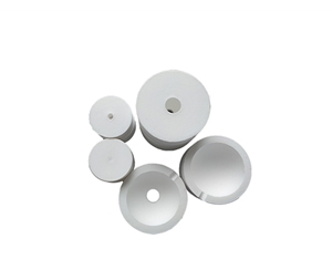
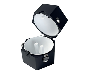
High-temperature molded PTFE diffuse white boards reach up to 99% reflectance across 250–2500 nm, are water-resistant, and resist chalking or yellowing over time. Sizes run from φ27 mm to 300 × 300 mm. These belong inside integrating spheres, spectrometer systems, and remote sensing instruments as master references. Production lines and field crews calibrate secondary panels against them; they are not meant to be carried outdoors daily.
LiDAR Panels Own the 905 nm Single Point
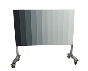
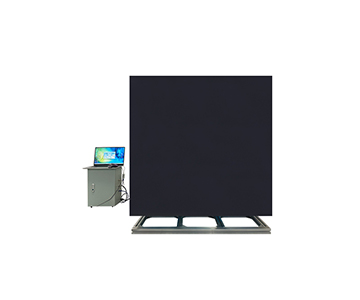
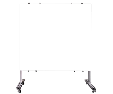
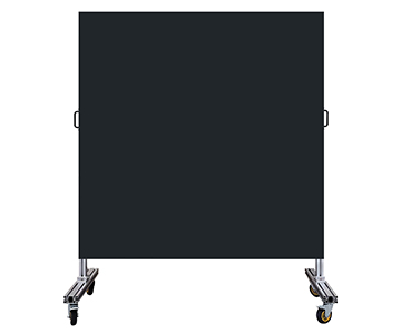
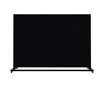
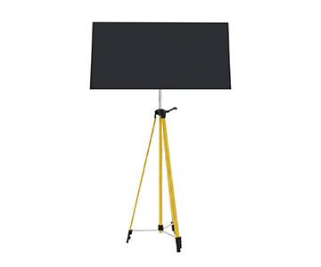
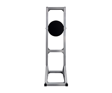
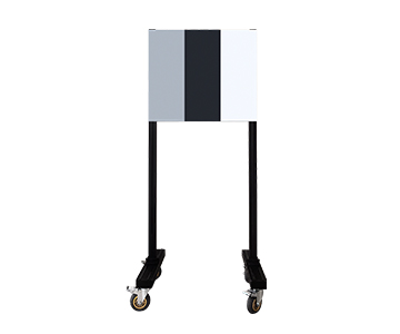
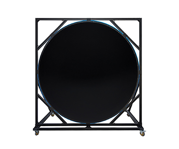
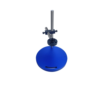
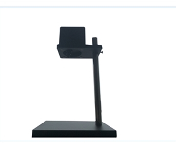
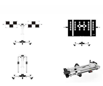
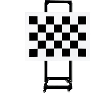
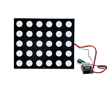
LiDAR-specific diffuse panels are optimized at 905 nm with 40% reflectance, ±1% accuracy, greater than 99.5% uniformity, and flatness below 0.4 mm/m², mounted on a roller stand adjustable from 0.8 to 1.3 m. They serve autonomous driving and handheld LiDAR distance calibration. The wavelength, traceability chain, and mount geometry differ from spectral white boards, so procurement should keep the two categories separate.
Reading Panel Specs Through a Drift Lens
Two parameters dominate long-term behavior: geometric stability and reflectance consistency over time. Absolute numbers matter less than how little they move.
Flatness Governs Oblique-Incidence Error
Geometric drift is the most underrated contributor. A flatness specification below 1 mm/m², combined with a 5 mm aluminum substrate, holds return signal stable through repeated clamping and thermal cycling. When flatness is lost, the mount has not moved but the panel has bowed, and readings shift in one direction. Read flatness and substrate thickness together; a thick aluminum base outperforms a thin plate over months.
Reflectance Consistency Beats Absolute Value
GB/T 47066-2026 defines total transmittance and total reflectance test methods for plastics, and Jingyi Optoelectronics participated as a drafting unit. Factory data follows that same reflectance-determination logic, giving multi-band values buyers can use as a cross-batch baseline. For traceability conversations in international procurement, the equivalent frame is ISO/IEC 17025 accredited measurement with NIST-traceable reference artifacts. An absolute 99% matters far less than 99% ±1% still holding six months later.
Before-and-After Data Worth Recording
Two deployment cases show what changes when panel architecture, packaging, and documentation are treated as one system.
Laboratory Plant Spectroscopy Bench
Measured over a 12-week qualification window on the same bench:
•Cross-batch grayscale deviation fell from 2.7% to 0.9%, a 66.7% reduction.
•Single calibration cycle time dropped from 46 minutes to 18 minutes, a 60.9% reduction.
Field Multispectral Flight Lines
A provincial agricultural remote sensing team replaced bare panels with a three-step kit plus aluminum case. Seasonal revisits of the same plot showed NDVI systematic offset falling from 0.041 to 0.013. The field lead noted that panels came out of the case clean enough to fly without re-cleaning, which the previous bare-panel workflow could not achieve.
Three Rules That Transfer Across Industries
These patterns hold whether the panel sits in a plant physiology lab, on a UAV, or in front of a LiDAR unit.
Grade the Reference, Do Not Buy One Tier
Use a PTFE master for laboratory traceability, secondary diffuse panels for daily production calibration, and cased multispectral panels for field flight lines. Three tiers doing three jobs cost less and drift less than buying every station a top-tier board.
Count Packaging Inside the Precision Budget
Aluminum cases, protective covers, and roller stands are not accessories. They decide whether the surface stays clean and flat between uses. Roughly half of long-term drift happens while the panel is stored, not while it is measuring.
Factory Reports Must Be Reproducible
A report should list band-by-band values, not a single 99%. Without a per-wavelength baseline, nobody can tell six months later whether the panel drifted or the instrument did.
Honest Limits and Operational Constraints
This panel architecture performs reliably in laboratory calibration, agricultural remote sensing, and single-point LiDAR checks, but it is not boundary-free.
PTFE boards resist water and weather, yet prolonged UV exposure still ages them slowly. Fixed outdoor stations need annual recertification and a replacement budget. The 50 × 20 mm dual-zone panel is too small for single-shot flat-field correction on a large-format camera; tiling or multi-point scanning introduces seam error as a new drift source. Operator discipline also matters: clamping angle, cleaning technique, and cover replacement must be written into a standard operating procedure, or human drift will erase the panel's advantage. Procurement teams should bake these constraints into the project SOP rather than expecting the hardware to solve them alone.
Procurement Validation and Long-Term Maintenance
Treat the panel as a metrology asset with a calibration schedule, not a consumable with a delivery date.
Ask About the Traceability Chain First
LiDAR projects should confirm conformity to T/CITS 231-2025 so the traceability chain covering target recognition and ranging accuracy stays intact. Spectral projects should compare factory data against GB/T 47066-2026 reflectance determination methods, or the ISO/IEC 17025 and NIST-traceable equivalent used by the purchasing region.
Run a Three-Tier Calibration Cadence
Factory baseline, per-shift daily check, and annual traceability recalibration turn a panel from consumable into asset. Log temperature, humidity, clamping angle, and cleaning batch alongside reflectance values. Those context records usually explain drift faster than the reflectance numbers alone.
Frequently Asked Questions
Should plant spectroscopy use a scale panel or a PTFE white board?
For routine multi-point retesting, the 10% plus 80% scale panel supplies dark and bright ends in one placement. For metrological traceability or integrating sphere work, use a PTFE white board up to 99% reflectance across 250–2500 nm. They complement each other rather than compete.
Why does a multispectral calibration kit need three reflectance levels?
A single level locks one response point, pushing highlight and shadow correction into extrapolation. The 25%, 50%, and 75% steps span the sensor dynamic range, and band-resolved factory reports keep red-edge and near-infrared channels consistent across flights.
Can a LiDAR calibration panel and a spectral white board be swapped?
No. The LiDAR panel is optimized at 905 nm with 40% reflectance and ±1% accuracy; the spectral board covers 250–2500 nm at up to 99%. Wavelength coverage, traceability chain, and mount geometry all differ, so mixing them blends two unrelated error budgets.
With a limited budget, which reflectance panel should come first?
Start with one PTFE standard white board as the master reference, then add secondary panels by scenario: a three-step multispectral kit for field work, a diffuse secondary panel for production lines. Expanding by drift trend beats buying every tier upfront.
How can I independently verify a reflectance panel's long-term stability?
Scan key bands at 10 nm steps with a traceable spectrometer and compare point by point against the factory report every six months. Record nine-point reflectance range, clamping angle, and ambient temperature and humidity at the same time. If the monotonic decline slope crosses your threshold, schedule recalibration or replacement instead of relying on supplier assurances.
About This Guide
Data Sources
: Internal validation reports on JY-RD scale panels, P4M multispectral calibration sets, JY-BRT series white boards, and JY-MRT series diffuse panels; GB/T 47066-2026 reflectance determination methods; ISO/IEC 17025 calibration principles.
Author
: Cai Xiaodong, Senior Application Engineer, Jingyi Optoelectronics, 15 years in optical inspection and spectrometer instrumentation, focused on reflectance traceability and production-line calibration.
Disclosure
: Jingyi Optoelectronics manufactures reflectance calibration panels. Technical assessments here draw on published specifications and aggregated industry data. No compensation was received from third-party brands mentioned.
Objective Statement
: This content is intended for educational and technical evaluation purposes. Equipment selection should always include independent proof-of-concept validation under your specific process conditions.
Last Updated
: November 2026
For detailed specifications and application notes on reflectance calibration panels, search “Jingyi Optoelectronics + reflectance panel” or visit our technical library.